


8HBW30
Toyota 8HBW30, 8HBE30, 8HBE40, 8HBC30, 8HBC40 Service Manual
...
88
SERVICE MANUAL
Pallet Trucks
8HBW30
8HBE40
8HBC40
36,001 and up
36,001 and up
36,001 and up
8HBE30
8HBC30
8TB50
36,001 and up
36,001 and up
36,001 and up
00700-CL398-07, Issued: 9 August 2007

Toyota Pallet Truck Service Manual Table of Contents
Table of Contents
How To Use This Manual . . . . . . . . . . . . . . . . . . . . . . . . . . . . . . . . . 1-1
Map of the Manual . . . . . . . . . . . . . . . . . . . . . . . . . . . . . . . . . . . . . . 1-2
Manual Design . . . . . . . . . . . . . . . . . . . . . . . . . . . . . . . . . . . . . . . . . 1-3
Abbreviations & Symbols . . . . . . . . . . . . . . . . . . . . . . . . . . . . . . . . . . 1-4
START Page . . . . . . . . . . . . . . . . . . . . . . . . . . . . . . . . . . . . . . . . . . . . 1-7
Safety . . . . . . . . . . . . . . . . . . . . . . . . . . . . . . . . . . . . . . . . . . . . . . . 2-1
Definitions . . . . . . . . . . . . . . . . . . . . . . . . . . . . . . . . . . . . . . . . . . . . . 2-2
General Safety . . . . . . . . . . . . . . . . . . . . . . . . . . . . . . . . . . . . . . . . . . 2-3
Battery Safety . . . . . . . . . . . . . . . . . . . . . . . . . . . . . . . . . . . . . . . . . . 2-6
Jacking Safety . . . . . . . . . . . . . . . . . . . . . . . . . . . . . . . . . . . . . . . . . . 2-9
Tie-Down for Transport . . . . . . . . . . . . . . . . . . . . . . . . . . . . . . . . . . 2-10
Towing . . . . . . . . . . . . . . . . . . . . . . . . . . . . . . . . . . . . . . . . . . . . . . 2-11
Welding Safety . . . . . . . . . . . . . . . . . . . . . . . . . . . . . . . . . . . . . . . . . 2-12
Static Safety . . . . . . . . . . . . . . . . . . . . . . . . . . . . . . . . . . . . . . . . . . 2-13
Systems Overview . . . . . . . . . . . . . . . . . . . . . . . . . . . . . . . . . . . . . . 3-1
Truck Model Identification . . . . . . . . . . . . . . . . . . . . . . . . . . . . . . . . . 3-2
Vehicle Specifications . . . . . . . . . . . . . . . . . . . . . . . . . . . . . . . . . . . . 3-3
Maximum Speeds . . . . . . . . . . . . . . . . . . . . . . . . . . . . . . . . . . . . . . . 3-4
General System Data . . . . . . . . . . . . . . . . . . . . . . . . . . . . . . . . . . . . . 3-5
Special Tools . . . . . . . . . . . . . . . . . . . . . . . . . . . . . . . . . . . . . . . . . . . 3-7
Theory of Operation . . . . . . . . . . . . . . . . . . . . . . . . . . . . . . . . . . . . . . 3-8
Planned Maintenance . . . . . . . . . . . . . . . . . . . . . . . . . . . . . . . . . . . 4-1
Maintenance Guidelines . . . . . . . . . . . . . . . . . . . . . . . . . . . . . . . . . . 4-2
Initial 90 Day/250 Deadman Hours (HD) Maintenance . . . . . . . . . . . 4-3
Every 180 Days or 500 Deadman Hours . . . . . . . . . . . . . . . . . . . . . . 4-4
Every 360 Days or 2000 Deadman Hours (HD) . . . . . . . . . . . . . . . . . 4-6
Grease Fittings . . . . . . . . . . . . . . . . . . . . . . . . . . . . . . . . . . . . . . . . . 4-7
Troubleshooting . . . . . . . . . . . . . . . . . . . . . . . . . . . . . . . . . . . . . . . 5-1
How to Use This Section . . . . . . . . . . . . . . . . . . . . . . . . . . . . . . . . . . 5-2
Electrical Troubleshooting Guidelines . . . . . . . . . . . . . . . . . . . . . . . . 5-3
DC Electric Motor Tests . . . . . . . . . . . . . . . . . . . . . . . . . . . . . . . . . . . 5-7
AC Electric Motor Tests . . . . . . . . . . . . . . . . . . . . . . . . . . . . . . . . . . . 5-9
Hydraulic Troubleshooting Guidelines . . . . . . . . . . . . . . . . . . . . . . . 5-10
Definitions . . . . . . . . . . . . . . . . . . . . . . . . . . . . . . . . . . . . . . . . . . . . 5-11
List of Electrical Symbols . . . . . . . . . . . . . . . . . . . . . . . . . . . . . . . . . 5-15
Operator Display and Programming . . . . . . . . . . . . . . . . . . . . . . . . . 5-17
Service Input/Output Displays . . . . . . . . . . . . . . . . . . . . . . . . . . . . 5-23
Traction Power Amplifier LED Diagnostics . . . . . . . . . . . . . . . . . . . . 5-26
Traction Power Amplifier Flash Codes . . . . . . . . . . . . . . . . . . . . . . . 5-27
Troubleshooting Flowcharts . . . . . . . . . . . . . . . . . . . . . . . . . . . . . . . 5-29
Caution and Error Codes . . . . . . . . . . . . . . . . . . . . . . . . . . . . . . . . . 5-33
Symptom Tables: Lift/Lower System . . . . . . . . . . . . . . . . . . . . . . . . 5-55
Symptom Tables: Travel (Forward/Reverse) System . . . . . . . . . . . . . 5-59
Symptom Tables: Wiring System . . . . . . . . . . . . . . . . . . . . . . . . . . . 5-68
Pinout Matrix . . . . . . . . . . . . . . . . . . . . . . . . . . . . . . . . . . . . . . . . . 5-69
Component Procedures . . . . . . . . . . . . . . . . . . . . . . . . . . . . . . . . . . 6-1
List of Component Procedures . . . . . . . . . . . . . . . . . . . . . . . . . . . . . . 6-2
Component Locator Photos . . . . . . . . . . . . . . . . . . . . . . . . . . . . . . . . 6-5
Tractor Cover . . . . . . . . . . . . . . . . . . . . . . . . . . . . . . . . . . . . . . . . . . 6-7
00700-CL398-07, Issued: 9 August 2007 i

Table of Contents Toyota Pallet Truck Service Manual
Battery . . . . . . . . . . . . . . . . . . . . . . . . . . . . . . . . . . . . . . . . . . . . . . . 6-8
Power Cables . . . . . . . . . . . . . . . . . . . . . . . . . . . . . . . . . . . . . . . . . 6-11
Wiring Harness . . . . . . . . . . . . . . . . . . . . . . . . . . . . . . . . . . . . . . . . 6-12
Fuses . . . . . . . . . . . . . . . . . . . . . . . . . . . . . . . . . . . . . . . . . . . . . . . 6-14
Switches (General) . . . . . . . . . . . . . . . . . . . . . . . . . . . . . . . . . . . . . 6-15
Key Switch (SW1) . . . . . . . . . . . . . . . . . . . . . . . . . . . . . . . . . . . . . . 6-16
Brake (Deadman) Switch (SW2) . . . . . . . . . . . . . . . . . . . . . . . . . . . . 6-17
Lift-Limit Switch (SW8) . . . . . . . . . . . . . . . . . . . . . . . . . . . . . . . . . . 6-19
Grab Rail Switches . . . . . . . . . . . . . . . . . . . . . . . . . . . . . . . . . . . . . 6-20
Hydraulic Solenoids . . . . . . . . . . . . . . . . . . . . . . . . . . . . . . . . . . . . 6-21
Jog Pick Solenoid . . . . . . . . . . . . . . . . . . . . . . . . . . . . . . . . . . . . . . 6-22
Horn . . . . . . . . . . . . . . . . . . . . . . . . . . . . . . . . . . . . . . . . . . . . . . . . 6-24
Traction Power Amplifier . . . . . . . . . . . . . . . . . . . . . . . . . . . . . . . . . 6-25
AMP Harness/Traction Power Amplifier Connector . . . . . . . . . . . . . 6-27
Contactors . . . . . . . . . . . . . . . . . . . . . . . . . . . . . . . . . . . . . . . . . . . 6-30
Control Handle Assembly . . . . . . . . . . . . . . . . . . . . . . . . . . . . . . . . 6-33
Control Handle . . . . . . . . . . . . . . . . . . . . . . . . . . . . . . . . . . . . . . . . 6-36
Brake . . . . . . . . . . . . . . . . . . . . . . . . . . . . . . . . . . . . . . . . . . . . . . . 6-41
Motors, General . . . . . . . . . . . . . . . . . . . . . . . . . . . . . . . . . . . . . . . 6-45
Traction Motor . . . . . . . . . . . . . . . . . . . . . . . . . . . . . . . . . . . . . . . . 6-46
AC Motor Service . . . . . . . . . . . . . . . . . . . . . . . . . . . . . . . . . . . . . . . 6-49
Drive Unit . . . . . . . . . . . . . . . . . . . . . . . . . . . . . . . . . . . . . . . . . . . . 6-51
Drive Wheel . . . . . . . . . . . . . . . . . . . . . . . . . . . . . . . . . . . . . . . . . . . 6-60
Casters (Torsion) . . . . . . . . . . . . . . . . . . . . . . . . . . . . . . . . . . . . . . . 6-63
Casters (Spring-Loaded) . . . . . . . . . . . . . . . . . . . . . . . . . . . . . . . . . 6-65
Load Wheels . . . . . . . . . . . . . . . . . . . . . . . . . . . . . . . . . . . . . . . . . . 6-69
Pallet Entry Sliders . . . . . . . . . . . . . . . . . . . . . . . . . . . . . . . . . . . . . 6-72
Fork Height Adjustment . . . . . . . . . . . . . . . . . . . . . . . . . . . . . . . . . 6-73
Hydraulic Components . . . . . . . . . . . . . . . . . . . . . . . . . . . . . . . . . . 6-75
Hydraulic Fluid . . . . . . . . . . . . . . . . . . . . . . . . . . . . . . . . . . . . . . . . 6-76
Adjusting Hydraulic Pump Relief Valve Pressure . . . . . . . . . . . . . . . 6-77
Hydraulic Ram . . . . . . . . . . . . . . . . . . . . . . . . . . . . . . . . . . . . . . . . 6-79
Hydraulic Unit . . . . . . . . . . . . . . . . . . . . . . . . . . . . . . . . . . . . . . . . 6-85
Lift Motor . . . . . . . . . . . . . . . . . . . . . . . . . . . . . . . . . . . . . . . . . . . . 6-89
Cold Storage Conditioning . . . . . . . . . . . . . . . . . . . . . . . . . . . . . . . . 6-91
Appendix . . . . . . . . . . . . . . . . . . . . . . . . . . . . . . . . . . . . . . . . . . . . . A-1
Lubrication Equivalency Chart . . . . . . . . . . . . . . . . . . . . . . . . . . . . . A-2
Torque Chart - Standard (Ferrous) . . . . . . . . . . . . . . . . . . . . . . . . . . A-3
Torque Chart - Standard (Brass) . . . . . . . . . . . . . . . . . . . . . . . . . . . . A-4
Torque Chart - Metric . . . . . . . . . . . . . . . . . . . . . . . . . . . . . . . . . . . . A-5
Torque Chart - Thread-Forming Screws . . . . . . . . . . . . . . . . . . . . . . . A-6
Decimal Equivalent Chart . . . . . . . . . . . . . . . . . . . . . . . . . . . . . . . . . A-7
Standard/Metric Conversions . . . . . . . . . . . . . . . . . . . . . . . . . . . . . . A-9
Electrical Schematics . . . . . . . . . . . . . . . . . . . . . . . . . . . . . . . . . . . . B-1
Index . . . . . . . . . . . . . . . . . . . . . . . . . . . . . . . . . . . . . . . . . . . . . . . . I-1
ii 00700-CL398-07, Issued: 9 August 2007

Toyota Pallet Truck Service Manual How To Use This Manual
Section 1. How To Use This Manual
00700-CL398-07, Issued: 9 August 2007 1-1
Toyota Pallet Truck Service Manual
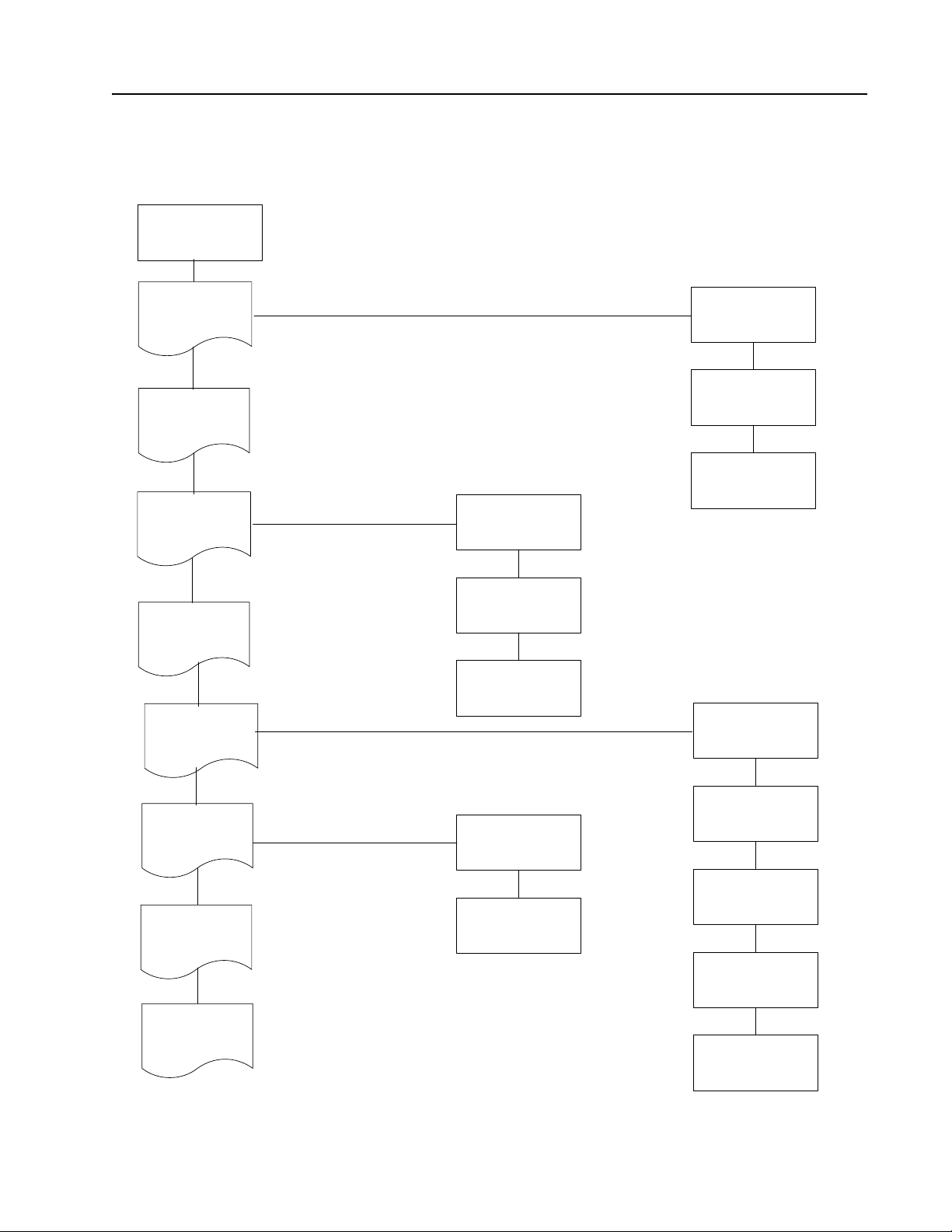
Map of the Manual
Table of Contents
and Page
Revision Record
How to Use This
Manual
Safety
Map of the Manual
Manual Design
Start Page
Systems
Overview
Scheduled
Maintenance
Trouble-
Shooting
Component
Procedures
Appendix
Vehicle
Specifications
General System
Data
Theory of
Operations
Alphabetical List
of Component
Procedures
Component
Locator Photos
Electrical &
Hydraulic T.S.
Guidelines
Definitions
Control Handle
Display &
Programming
Fault Codes &
Caution & Error
Codes
Index
Troubleshooting
Charts and
Symptom Tables
1Map.wmf
00700-CL398-07 Issued: 9 August 2007 1-2

Toyota Pallet Truck Service Manual How To Use This Manual
Manual Design
Manual Design
The Toyota Pallet Truck Service Manual is
designed with the following objectives in mind:
• Provide technical coverage for expected
levels of user expertise
• Anticipate your needs and reduce your
decisions regarding maintenance
• Reduce page flipping thru a “one-stop
shopping” approach
The two-line running page header at the top of
each page tells you:
• Name of the manual (Toyota Pallet Truck
Service Manual)
• Current section title
(for example, this page How to Use This
Manual)
• Current topic
(for example, this page Manual Design)
We suggest you get in the habit of turning to the
START page first when you use this manual.
•The START page asks a few questions to
guide you to the correct section.
How to Use This Manual explains the manual
format and contains the START page.
Safety explains warning and caution notes,
general safety rules and safety rules for
batteries, static, jacking, and welding.
• The section “Caution and Error Codes”
on page 5-33 defines the various codes
displayed on the operator display.
•The chart “TS1: START
TROUBLESHOOTING” on page 5-29 will
guide you to the symptom chart you need.
• When you’re familiar with the symptoms
listed, you may simply look up the
symptom from the “Troubleshooting” on
page 5-29.
• As you work with a troubleshooting chart,
code, or table, you may be instructed to
test various electrical connector pins. The
pinout matrix chart lists information on
functions and normal voltages of terminals
and harness connector pins. See “Pinout
Matrix” on page 5-69.
• When you complete a troubleshooting
procedure, perform the steps in the
“END1: End of Troubleshooting
Procedure” on page 5-31.
Component Procedures gives step-by-step
procedures for testing, removal, installation,
and adjustment of individual truck
components. Components are listed in an order
that considers:
• Frequency of attention
• Physical attachment (for example, remove
the brake before the traction motor)
• Functional relation (for example, traction
motor and drive unit components are
grouped together)
Systems Overview includes truck
specifications and theory of operation
information.
Planned Maintenance outlines the
recommended schedule of preventive services to
keep your truck working most efficiently.
Troubleshooting is a set of fault, caution, and
error codes, charts and tables designed to take
you from a symptom to a specific sequence of
actions in order to isolate a failing component.
•The chart “Traction Power Amplifier
Flash Codes” on page 5-27 will guide you
thru the flash codes displayed on the
LED’s installed on the TA.
To find a component procedure, you may use
one of three methods:
• Look up the component name in the “List
of Component Procedures” on page 6-2.
• Find the component in the “Component
Locator Photos” on page 6-5.
• Look up component name in the “Index”.
Appendix contains reference information such
as torque values, lubricants, and schematics.
Index lists subjects alphabetically.
00700-CL398-07, Issued: 9 August 2007 1-3

How To Use This Manual Toyo ta Pallet Truck Service Manual
Abbreviations & Symbols
Abbreviations &
Symbols
These abbreviations, acronyms and symbols are used in this manual.
Term/Symbol Definition Term/Symbol Definition
AAmpere
AC Alternating Current
amp Ampere or amplifier
ANSI American National Standards
Institute
approx approximately
aux auxiliary
AWG American Wire Gauge
BSOC Battery State-of-Charge
CAN Controller Area Network
CCW counterclockwise
cm centimeter
COP Computer Operating Program
CV checkvalve
CW clockwise
DC Direct Current
DGND digital ground
EE UL Electric Truck Type
Certification Rating where
electrical equipment is completely
enclosed
ESD Electrostatic Discharge
ETAC Electronic Tiller Arm Control (See
Vehicle Manager)
ft. foot or feet
gal. gallon or gallons
Gnd ground
km/hr kilometers per hour
kPa kilo Pascal
lb. pound or pounds
LED Light Emitting Diode
L/H Load Holding
L/L Lift/Lower
mA milliampere
mm millimeter
mph miles per hour
ms millisecond(s)
N/A Not Applicable or Not Available
N•m newton meter
OD Operator’s Display
OSHA Occupational Safety and Health
Administration
oz. ounce
pot potentiometer
psi pounds per square inch
PWM Pulse Width Modulation
P/N Part Number
RAM Random Access Memory
RCFP Relay Control Fuse Panel
ROM Read Only Memo ry
RPM Revolutions per Minute
R/R Remove and Replace
HD hours on deadman
in. inch or inches
kg kilogram(s)
SOL Solenoid
spec specification
SPI Service Port Interface
1-4 00700-CL398-07, Issued: 9 August 2007

Toyota Pallet Truck Service Manual How To Use This Manual
Abbreviations & Symbols
Term/Symbol Definition
TPA Traction Power Amplifier
temp Temperature
TM Traction Motor
TS troubleshoot
UL Underwriters Laboratories, Inc.
V Volt or Volts
VAC Volts Alternating Current
VDC Volts Direct Current
VM Vehicle Manager (ETAC)
wrt with respect to
@at
™ trademark
© copyright
+ plus or positive
– mi nus or negative
± plus or minus
° degrees
°F degrees Fahrenheit
°C degrees Celsius
< less than
> greater than
% percent
= equals
00700-CL398-07, Issued: 9 August 2007 1-5
Toyota Pallet Truck Service Manual How To Use This Manual
START Page
Section 1. How To Use This Manual
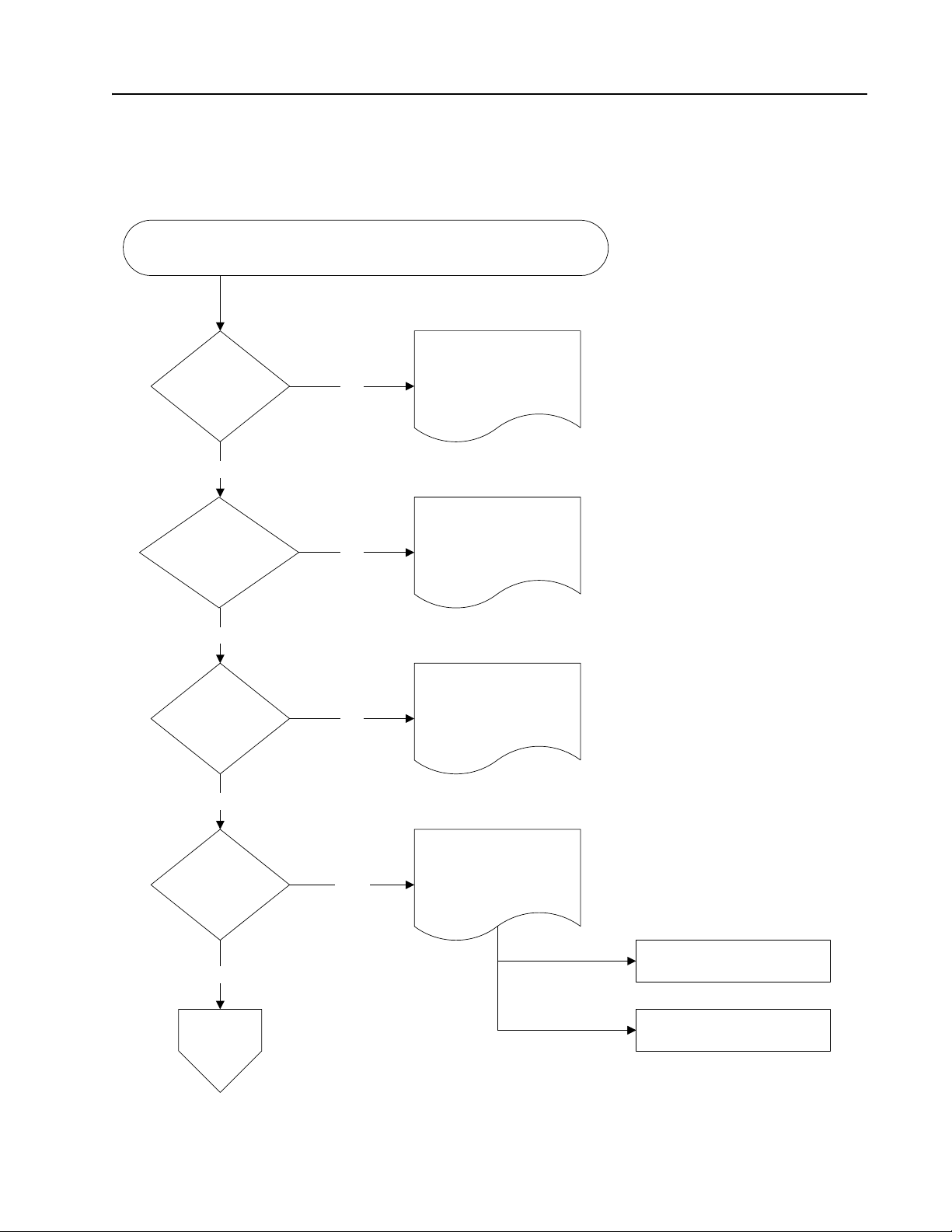
START Page
START: Why are you here?
Go to Section 2
To review safety
precautions?
No
Yes
"Safety"
To examine
specifications or
theory of
operations?
No
To do scheduled
maintenance?
No
To troubleshoot
a problem?
No
Yes
Yes
Yes
Go to Section 3
"Systems Overview"
Go to Section 4
"Scheduled Maintenance"
Go to Section 5
"Troubleshooting"
List of Caution and Error
Codes
Go to Chart
START-2
START Troubleshooting
1Startpg1.wmf
00700-CL398-07, Issued: 9 August 2007 1-7
How To Use This Manual Toyo ta Pallet Truck Service Manual
START Page
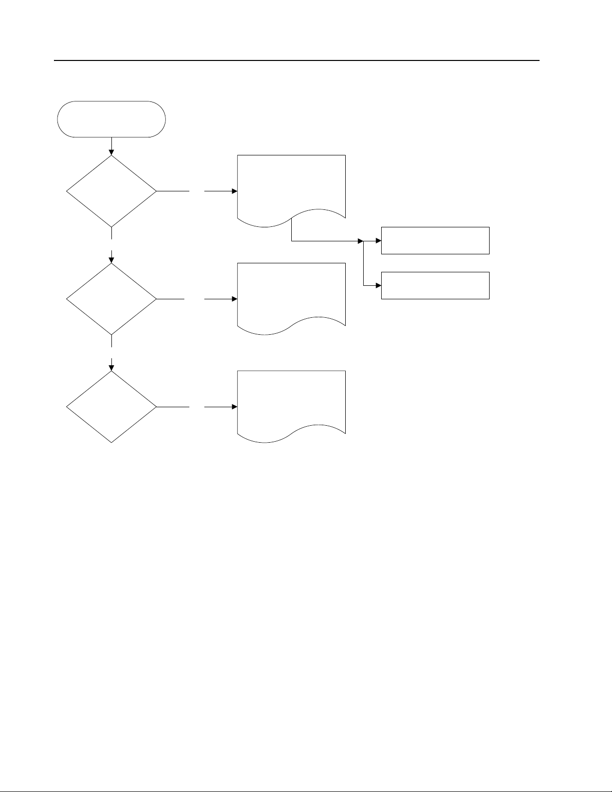
START-2
To test,
inspect, adjust,
remove/install a
component?
No
To find general
reference
information?
No
To locate
an object or
procedure by
name?
Yes
Yes
Yes
Go to Section 6
"Component Procedures"
Go to the
"Appendix"
Go to the Index
Alphabetical List of
Component Procedures
Component Locator
1Startpg2.wmf
1-8 00700-CL398-07, Issued: 9 August 2007

Toyota Pallet Truck Service Manual Safety
Section 2. Safety
00700-CL398-07, Issued: 9 August 2007 2-1

Safety Toyot a Pallet Truck Service Manual
Definitions
Definitions
In this manual, you will see two kinds of safety
reminders:
A warning specifies a potentially
hazardous situation that, if not
prevented, could result in death or
serious injury.
A caution specifies a potentially
hazardous situation that, if not avoided,
could result in minor or moderate injury
or in damage to the lift truck or nearby
objects. A caution can also alert against
unsafe practices.
2-2 00700-CL398-07, Issued: 9 August 2007
Toyota Pallet Truck Service Manual Safety
General Safety
General Safety
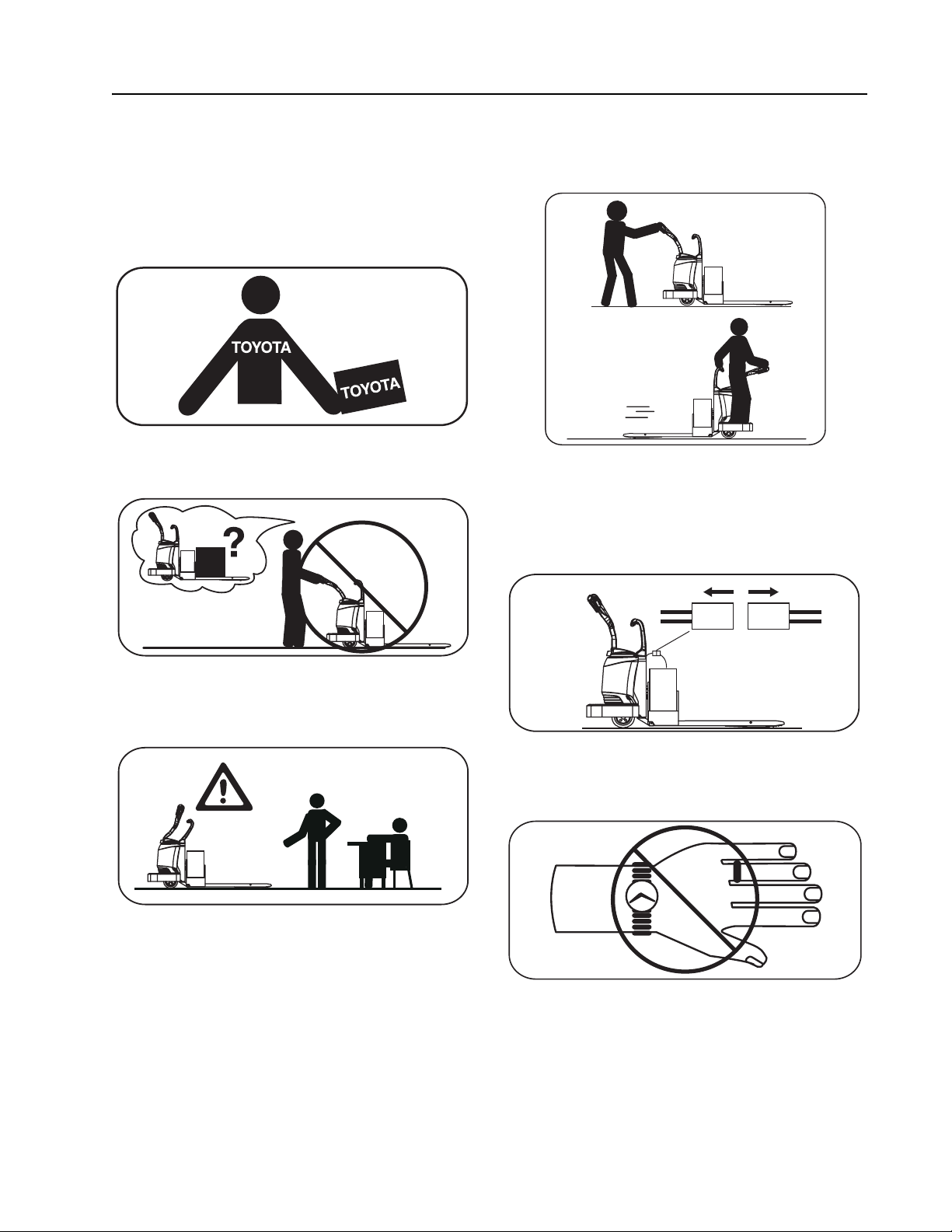
Do not operate or work on this truck unless you
are trained, qualified and authorized to do so,
and have read the Owner/Operator Manual.
2
Know the truck’s controls and what they do.
Operate this truck only from the operator’s
position.
2O-7.eps
Before working on this truck, always turn the
key switch to OFF and disconnect the truck’s
battery connector (unless this manual tells you
otherwise).
2
Do not operate this truck if it needs repair or if
it is in any way unsafe.
2O-6.eps
2S-1.eps
Do not wear watches, rings, or jewelry when
working on this truck.
21864 067.eps
00700-CL398-07, Issued: 9 August 2007 2-3
Safety Toyot a Pallet Truck Service Manual
General Safety
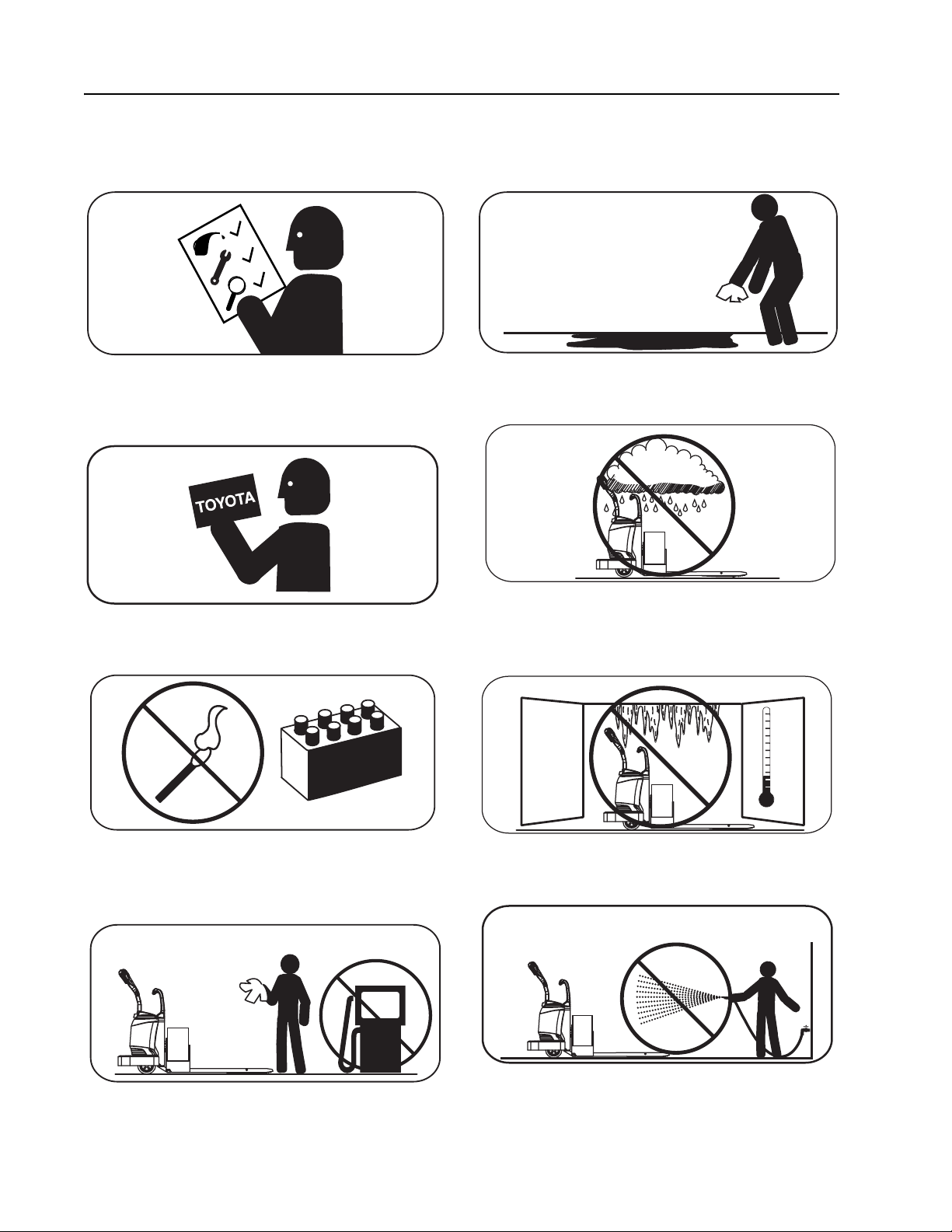
Obey the scheduled lubrication, maintenance,
and inspection steps.
2Schedmnt.eps
Obey exactly the safety and repair instructions
in this manual. Do not take “shortcuts.”
2
Do not use an open flame near the truck.
Clean up any hydraulic fluid, oil, or grease that
has leaked or spilled on the floor.
2Spills.eps
Always park this truck indoors.
2O-63.eps
Do not park this truck in a cold storage area
overnight.
223L6S012.eps
Do not use gasoline or other flammable liquids
Do not wash this truck with a hose.
2
for cleaning parts.
2
2
2-4 00700-CL398-07, Issued: 9 August 2007
 Loading...