


 Loading...
E6581830
TOSVERT VF-S15 series
 ® option unit Function Manual CCL003Z
NOTICE
1.Read this manual before installing or operating. Keep this instruction manual on hand of the end user, and make use of this manual in maintenance and inspection.
2.All information contained in this manual will be changed without notice. Please contact your Toshiba distributor to confirm the latest information.

E658130
Introduction
Thank you for purchasing the “CC-Link® option (CCL003Z)” for TOSVERT VF-S15 drive. This option can connect with open field network CC-Link and data communications with the CC-Link master through installing this option in the VF-S15 and using it. Besides this instruction manual, the “CC-Link option Instruction Manual” is required to develop software communicating with VF-S15.
This option needs the option adaptor to connect VF-S15 which type form is SBP009Z. Please match here and buy it when SBP009Z is not at hand yet.
After reading this function manual, please keep it handy for future reference.
For details of its general handling, see an instruction manual attached with the option unit.
-TOSVERT VF-S15 Instruction Manual ·························································· E6581611
-TOSVERT VF-MB1/S15 communication option Precautions Manual··········· E6581739
-TOSVERT VF-S15 Communication Function Instruction Manual················· E6581913
CC-Link® is a registered trademark of Mitsubishi Electric Corporation.
- 1 -
E658130

 Handling in general
 Warning
|
|
|
Do not connect or disconnect a network cable while the drive power is on. |
|
Prohibited |
It may lead to electric shocks or fire. |
|
|
|
||
|
|
|
See the instruction manual attached with the option unit for cautions the handling. |
|
Mandatory |
Otherwise, it may lead to electric shocks, fire, injuries or damage to product. |
|
|
|
||
|
|
Network control |
|
|
|
||
|
|
||
|
|
|
Warning |
|
|
|
Do not send the value out of the valid range to objects and attributes. |
|
Prohibited |
Otherwise, the motor may suddenly start/stop and that may result in injuries. |
|
|
|
||
|
|
|
Use an additional safety device with your system to prevent a serious accident due to the |
|
Mandatory |
network malfunctions. Usage without an additional safety device may cause an accident. |
|
|
|
||
|
|
|
Caution |
|
Set up “Communication error trip function (see below)” to stop the drive when the option |
|
|
unit is deactivated by an unusual event such as tripping, an operating error, power |
|
|
outage, failure, etc. |
|
|
- Network Time-Out, drive operation at disconnection, Preset speed operation |
|
|
selection |
|
Mandatory |
(Refer to 5.2 for details) |
|
Deactivated the option module may cause an accident, if the “Communication error trip |
||
|
||
|
function” is not properly set up. |
 Make sure that the operation signals are STOP before resetting drive’s fault. The motor may suddenly start and that may result in injuries.

 Notes on operation
Notes
 When the control power is shut off by the instantaneous power failure, communication will be unavailable for a while.
 The Life of EEPROM is approximately 100,000 times. Avoid writing a command more than 100,000 times to the same parameter of the drive and the option module.
- 2 -

|
|
|
|
E658130 |
|
|
|||
Table of Contents |
|
|||
1. |
OVERVIEW ............................................................................................................................................ |
- 4 - |
||
2. |
BASIC SPECIFICATIONS..................................................................................................................... |
- 4 - |
||
|
2.1. |
CC-Link Version .............................................................................................................................. |
- 5 - |
|
|
2.1.1. |
CC-Link Ver. 1.10 .................................................................................................................... |
- 5 - |
|
|
2.1.2. |
CC-Link Ver. 2 ......................................................................................................................... |
- 5 - |
|
3. |
NAMES AND FUNCTIONS ................................................................................................................... |
- 6 - |
||
|
3.1. |
Outline ............................................................................................................................................. |
- 6 - |
|
4. |
INSTALLATION ON INVERTER ........................................................................................................... |
- 7 - |
||
|
4.1. |
Connection cable ............................................................................................................................ |
- 7 - |
|
|
4.2. |
Terminating resistor ........................................................................................................................ |
- 7 - |
|
|
4.3. Connection of CC-Link master unit and inverter............................................................................. |
- 8 - |
||
|
4.4. The maximum connection number of units..................................................................................... |
- 9 - |
||
|
4.5. |
LED indicator................................................................................................................................. |
- 11 - |
|
5. |
FUNCTIONS ........................................................................................................................................ |
- 12 - |
||
|
5.1. |
Initial setting .................................................................................................................................. |
- 12 - |
|
|
5.2. Communication parameters for CCL003Z .................................................................................... |
- 13 - |
||
|
5.3. |
CC-Link function setting................................................................................................................ |
- 14 - |
|
|
5.3.1. |
Station number setting........................................................................................................... |
- 14 - |
|
|
5.3.2. |
Baud rate setting.................................................................................................................... |
- 14 - |
|
|
5.3.3. |
CC-Link extended setting ...................................................................................................... |
- 15 - |
|
|
5.4. |
Basic functions .............................................................................................................................. |
- 16 - |
|
|
5.4.1. Run and frequency operation command ............................................................................... |
- 16 - |
||
|
5.4.2. |
Monitor ................................................................................................................................... |
- 16 - |
|
|
5.4.3. Writing and reading the parameter ........................................................................................ |
- 16 - |
||
|
5.5. |
I/O signal list.................................................................................................................................. |
- 17 - |
|
|
5.5.1. One station is occupied (CC-Link Ver.1) (c122=0)........................................................... |
- 17 - |
||
|
5.5.2. Double setting is selected (CC-Link Ver.2) (c122=1) ....................................................... |
- 18 - |
||
|
5.5.3. Quadruple setting is selected (CC-Link Ver.2) (c122=2).................................................. |
- 18 - |
||
|
5.5.4. Octuple setting is selected (CC-Link Ver.2) (c122=3) ...................................................... |
- 19 - |
||
|
5.5.5. |
Faults history.......................................................................................................................... |
- 20 - |
|
|
5.5.6. Detail of input and output signals........................................................................................... |
- 21 - |
||
|
5.5.7. |
Remote Register Assignment ................................................................................................ |
- 24 - |
|
|
5.5.8. |
Instruction Codes ................................................................................................................... |
- 28 - |
|
|
5.5.9. The details of an error code................................................................................................... |
- 30 - |
||
|
5.5.10. |
Description of reply code.................................................................................................... |
- 32 - |
|
|
5.5.11. |
Description of monitor code ............................................................................................... |
- 33 - |
|
|
5.5.12. |
Description of input terminal information............................................................................ |
- 34 - |
|
|
5.5.13. |
Description of output terminal information ......................................................................... |
- 34 - |
|
6. |
PROGRAMMING EXAMPLES ............................................................................................................ |
- 35 - |
||
|
6.1. Program example for reading the inverter status.......................................................................... |
- 38 - |
||
|
6.2. Program example for setting the operation mode......................................................................... |
- 39 - |
||
|
6.3. Program example for setting the operation commands................................................................ |
- 40 - |
||
|
6.4. Program example for setting the running frequency..................................................................... |
- 40 - |
||
|
6.5. Program example for monitoring the output frequency................................................................. |
- 41 - |
||
|
6.6. Program example for parameter writing........................................................................................ |
- 42 - |
||
|
6.7. Program example for parameter reading...................................................................................... |
- 43 - |
||
|
6.8. Program example for fault record reading .................................................................................... |
- 44 - |
||
|
6.9. Program example for resetting the inverter at inverter error......................................................... |
- 45 - |
||
|
6.10. |
Instructions ................................................................................................................................ |
- 46 - |
|
7. |
UNUSUAL DIAGNOSIS....................................................................................................................... |
- 47 - |
||
|
7.1. |
Option error ................................................................................................................................... |
- 47 - |
|
|
7.2. Disconnection error of network cable ........................................................................................... |
- 47 - |
||
|
7.3. How to check the error using the LEDs ........................................................................................ |
- 48 - |
||
- 3 -

E658130
1.Overview
The option allows the VF-S15 drive to be connected into a CC-Link network. CC-Link supports a maximum of 42 nodes, allowing for the Master and this option is based on CC-Link V1.1 and V2.0.
The CCL-003Z is able to operate RUN/STOP, monitor the status of the drive, set the drive’s parameter and etc. by the CC-Link master through installing the VF-S15. And it can use various applications.
2.Basic specifications
<Environmental specification>
Item |
Specification |
Operating |
Indoors, an altitude of 3,000m or less, where the product will not be exposed |
environment |
to direct sunlight, corrosive or explosive gasses, vapor, coarse particulates |
|
including dust and where there is no grinding fluid or grinding oil nearby. |
Ambient |
0 to + 60 degreeC |
temperature |
|
Storage |
-25 to +65 degreeC |
temperature |
|
Related |
20 to 93% (no condensation and absence of vapor) |
temperature |
|
Vibration |
5.9 m/s2 (0.6G) or less (10 – 55Hz) |
<CC-Link communication and option specification> |
|
Item |
Specification |
Number of units |
42 units max. (1 station occupied by 1 unit). May be used with other |
corrected |
equipment. |
Baud rate |
156k, 625k, 2.5M, 5M, 10Mbps |
Power supply |
Supplied from SBP009Z |
Station type |
Remote device station |
Number of stations |
Ver.1: occupies one station, V2: occupies one station (selectable from among |
occupied |
double, quadruple and octuple) |
Connect cable |
CC-Link dedicated cable, |
|
CC-Link V1.10 compatible CC-Link dedicated cable |
- 4 -

E658130
2.1. CC-Link Version
2.1.1.CC-Link Ver. 1.10
The conventional CC-Link products, whose inter-station cable lengths have equally been changed to 20cm (7.87 inch) or more to improve the inter-station cable length restriction, are defined as CC-Link Ver. 1.10. In comparison the conventional products are defined as CC-link Ver. 1.00.
Refer to the CC-link Master Module Manual for the maximum overall cable lengths and inter-station cable lengths of CC-Link Ver. 1.00 and Ver. 1.10
CC-Link Ver. 1.10 compatibility conditions
1)All modules that comprise a CC-Link system should be compatible with CC-Link Ver. 1.10.
2)All data link cables should be CC-Link Ver. 1.10 compatible, CC-Link dedicated cables. (CC-Link Ver.1.10 compatible cables have a logo or Ver. 1.10 indication.)
*In a system that uses the CC-Link Ver. 1.00 and Ver. 1.10 modules and cables together, the maximum overall cable length and inter-station cable length are as specified for CC-Link Ver. 1.00.
2.1.2.CC-Link Ver. 2
The CCL003Z is compatible with CC-Link Ver.2.
When using the CC-Link Ver.2 setting with the CCL003Z, the master station needs to be compatible with the CC-Link Ver.2.
For CC-Link Ver.2, double, quadruple and octuple settings can be used to increase remote register (RWw/r) point.
- 5 -

E658130
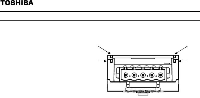
3.Names and functions
The drawing below shows names and functions of main parts.
3.1. Outline
Connector to the inverter
Release tab
LED indicator (See 4.5)
CC-Link Connector
DA DB DG SLD FG
- 6 -
E658130
4.Installation on inverter
Refer to VF-S15 option adapter instruction manual (E6581838) for the installation on the inverter.
|
The following steps must be performed before installing. |
|
Mandatory |
1. |
Shut off all input power. |
2. |
Wait at least 15 minutes and check to make sure that the charge lamp is no longer lit. |
|
4.1. Connection cable
In the CC-Link system, use CC-Link dedicated cables.
If the cable used is other than the CC-Link dedicated cable, the performance of the CC-Link system is not guaranteed.
For the specifications of the CC-Link dedicated cable, refer to the website of the CC-Link Partner Association.
Website: http://www.cc-link.org/
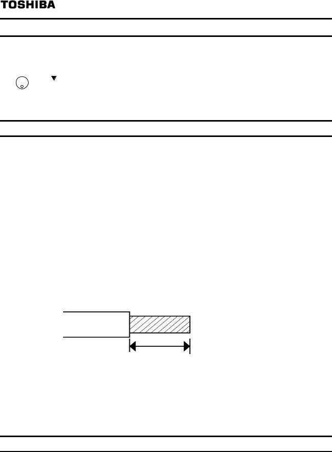
Strip off the sheath of the CC-Link dedicated cable and wind wires to use. If the length of the sheath pealed is too long, a short circuit may occur among neighboring wires. If the length is too short, wires might come off.
Recommended screwdriver Small flat-blade screwdriver
(Tip thickness: 0.4mm /tip width: 2.5mm)Recommented tightening Torque 0.22N m to 0.25N m
Cable stripping size About 7mm
mm
*Fix a cable so that a communication connector may be not taken the weight of wire. When the cable is not connected easily, the use of the following bar terminal is recommended.
Phoenix Contact Co. Ltd.
Bar terminal model: AI-TWIN2x0,5-8 WH Length of bar terminal: 8mm
4.2. Terminating resistor
Connect the terminating resistor of 110Ω or 130Ω (CC-Link Ver.1.00 dedicated high performance cable.) between terminals at the end.
- 7 -
E658130
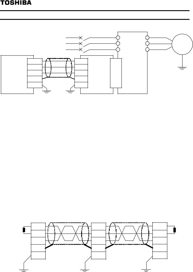
4.3. Connection of CC-Link master unit and inverter
The example of the connection of the CC-Link master unit and the inverter is shown.
R/L1
S/L2
T/L3
CC-Link |
DA |
DA |
|
|
DB |
DB |
|
||
Master |
CCL003Z |
|||
DG |
DG |
|||
Unit |
|
|||
SLD |
SLD |
|
||
|
|
|||
|
FG |
FG |
|
|
U/T1 |
Motor |
|
|
|
||
Inverter |
V/T2 |
I M |
|
VF-S15 |
W/T3 |
||
|
*Connection of Several Inverters
Factory Automation can be applied to several inverters which share a link system as CC-Link remote device stations and are controlled and monitored by PLC user programs.
DA,DB
Shield twisted cable
DG
SLD / FG
Connect the shielded wire of the dedicated CC-Link cable to the “SLD” of each module, and ground both ends of the shielded wire using type-D grounding (class 3 grounding) via “FG.”
(The ground resistance is 100Ω or less.)
Terminal resistor
Connect the terminal resistor of 110Ω.
(130Ω is a resistance value for the CC-Link Ver.1.00 dedicated high performance cable.)
Mater unit |
|
Inverter |
|
Inverter |
|
|
Terminal |
DA |
|
DA |
|
DA |
Terminal |
DB |
|
DB |
|
DB |
||
resistor |
|
|
resistor |
|||
DG |
|
DG |
|
DG |
||
110Ω 1/2W |
|
|
110Ω1/2W |
|||
SLD |
|
SLD |
|
SLD |
||
(130Ω 1/2W) |
Shield twisted cable |
Shield twisted cable |
(130Ω 1/2W) |
|||
|
FG |
|
FG |
|
FG |
|
- 8 -

E658130
4.4.The maximum connection number of units
1.Maximum number of units connected to one master station (CC-Link Ver.1.10) 42 units (when only inverters are connected)
If any other units are included, the number of stations occupied depends on the unit and therefore the following conditions must be satisfied:
{(1 × a) + (2 × b) + (3 × c) + (4 × d)} 64
a:Number of units occupying 1 station
b:Number of units occupying 2 stations
c:Number of units occupying 3 stations
d:Number of units occupying 4 stations
{(16 × A) + (54 × B) + (88 × C)} 2304
A:Number of remote I/O stations 64
B:Number of remote device stations 42
C:Number of local, standby master and intelligent device stations 26
- 9 -
E658130
2.Maximum number of units connected to one master station (CC-Link Ver.2.00) 42 units (when connections are inverter only)
If any other units are included, the number of stations occupied depends on the unit and therefore the following conditions must be satisfied:
{(a + a2 + a4 + a8) + (b + b2 + b4 + b8) × 2 + (c + c2 + c4 + c8) × 3 + (d + d2 + d4 + d8) × 4} 64
{(a × 32 + a2 × 32 + a4 × 64 + a8 × 128) + (b × 64 + b2 × 96 + b4 × 192 + b8 × 384)
+ (c × 96 + c2 × 160 + c4 × 320 + c8 × 640) + (d × 128 + d2 × 224 + d4 × 448 + d8 × 896)}8192
{(a × 4 + a2 × 8 + a4 × 16 + a8 × 32) + (b × 8 + b2 × 16 + b4 × 32 + b8 × 64)
+ (c × 12 + c2 × 24 + c4 × 48 + c8 × 96) + (d × 16 + d2 × 32 + d4 × 64 + d8 × 128)}
2048
a:Number of single setting devices occupying one station
b:Number of single setting devices occupying two stations
c:Number of single setting devices occupying three stations
d:Number of single setting devices occupying four stations a2: Number of double setting devices occupying one station b2: Number of double setting devices occupying two stations c2: Number of double setting devices occupying three stations d2: Number of double setting devices occupying four stations a4: Number of quadruple setting devices occupying one station
b4: Number of quadruple setting devices occupying two stations c4: Number of quadruple setting devices occupying three stations d4: Number of quadruple setting devices occupying four stations a8: Number of octuple setting devices occupying one station
b8: Number of octuple setting devices occupying two stations c8: Number of octuple setting devices occupying three stations
d8: Number of octuple setting devices occupying four stations 16 × A + 54 × B + 88 × C 2304
A:Numbers of remote I/O 64
B:Number of remote device stations 42
C:Number of local and intelligent device stations 26
- 10 -
E658130
4.5.LED indicator
The LEDs shows the present status of the network and module
Refer to 7.3 for detail.
L.RUN |
SD |
L.ERR |
RD |
■ Layout of LED
L.RUN |
Light on during communication. |
|
|
SD |
Light on during send the data of CC-Link. |
|
|
RD |
Light on during receive the data of CC-Link. |
|
|
L.ERR |
Light on during communication error. |
|
|
- 11 -

E658130
5.Functions
This option is a communication interface unit that allows the PLC program to operate, monitor and set the parameter of the inverter as a remote station of CC-Link. It is able to communicate with a maximum speed of 10Mbps not only transmitting bit data but also by word data.
Moreover, more data transmissions are possible by the use of CC-Link V2.0.
5.1. Initial setting
Set the following parameters of the inverter.
Title |
Function |
Description |
Factory |
CC-Link |
||
setting |
setting |
|||||
|
|
|
|
|||
|
|
|
0: Terminal board |
|
|
|
cmod |
Command mode |
1: Panel keypad (including remote keypad) |
1 |
4 |
||
2: RS485 communication |
||||||
|
selection |
|
||||
|
|
3: CANopen communication |
|
|
||
|
|
|
|
|
||
|
|
|
4: Communcation option |
|
|
|
|
|
|
0: Setting dial 1 (save even if power is off) |
|
|
|
|
|
|
1: Terminal board VIA |
|
|
|
|
|
|
2: Terminal board VIB |
|
|
|
|
|
|
3: Setting dial 2 (press in center to save) |
|
|
|
|
|
|
4: RS485 communication |
|
|
|
|
Frequency |
setting |
5: UP/DOWN from external logic input |
0 |
7 |
|
fmod |
6: CANopen communication |
|||||
mode selection 1 |
||||||
|
7: Communication option |
|
|
|||
|
|
|
|
|
||
|
|
|
8: Terminal board VIC |
|
|
|
|
|
|
9, 10: - |
|
|
|
|
|
|
11: Pulse train input |
|
|
|
|
|
|
12, 13: - |
|
|
|
|
|
|
14: sro |
|
|
|
|
|
|
1: 2 poles |
|
|
|
|
|
|
2: 4 poles |
|
|
|
|
Number of motor |
3: 6 poles |
|
|
||
|
4: 8 poles |
2 |
* |
|||
f856 |
pole for |
|
||||
|
5: 10 poles |
|||||
|
communication |
|
|
|
||
|
|
6: 12 poles |
|
|
||
|
|
|
|
|
||
|
|
|
7: 14 poles |
|
|
|
|
|
|
8: 16 poles |
|
|
|
f899 |
Communication |
0: - |
0 |
- |
||
function reset |
|
1: Reset (after execution: 0) |
||||
|
|
|
|
|||
*Set parameter according to number of motor pole used.
- 12 -

E658130
5.2.Communication parameters for CCL003Z
Title |
Function |
Description |
|
c100 |
Communication error detection |
0.0 - 100.0 sec. |
|
delay time |
|||
|
|
||
c101 |
|
0: Stop and controlled by cmod, fmod |
|
|
|
1: Operation continue |
|
|
Inverter operation at the |
2: Deceleration stop |
|
|
communication loss action |
3: Coast stop |
|
|
|
4: Network error stop (err8 trip) |
|
|
|
5: Preset speed operation (by c102 setting) |
|
c102 |
Preset speed |
0: None |
|
|
operation selection |
1 to 15: Preset speed |
|
c103 |
Communication time-out |
0: Disconnection detection |
|
|
1: When communication mode enable (Both cmod and |
||
|
condition selection |
fmod are set CANopen or communication option) only |
|
|
|
2: 1 + Driving operation |
|
c120* |
CC-Link station number |
1 to 64 |
|
|
selection |
Set the number of stations of inverters (Remote device |
|
|
|
||
|
|
station). |
|
c121* |
CC-Link baud rate selection |
0: 156kbps |
|
|
|
1: 625kbps |
|
|
|
2: 2.5Mbps |
|
|
|
3: 5Mbps |
|
|
|
4: 10Mbps |
|
|
|
Set the baud rate for CC-LINK network |
|
c122* |
CC-Link extended selection |
0: Occupies one station (V1.10) |
|
|
|
1: Occupies one station double (V2.0) |
|
|
|
2: Occupies one station quadruple (V2.0) |
|
|
|
3: Occupies one station octuple (V2.0) |
|
|
|
The function of remote registers can be enhanced. |
* Set parameters according to the CC-Link network system.
- 13 -

E658130
5.3.CC-Link function setting
5.3.1. Station number setting
Use parameter c120 to set station number of the inverter.
Set this parameter within the range of 1 to 64.
Title |
Function |
Description |
c120 |
CC-Link station |
1 to 64 |
|
number selection |
|
*Use different station numbers for different devices. (If different devices have the same station number, the communication cannot be performed properly.)
Set consecutive numbers for the station numbers. (Do not skip a number in sequence like "station number 1 - station number 2 - station number 4".)
The station number does not have to match with the physical connection sequence. (There is no problem with having the physical connection sequence like "station number 1 - station number 3 - station number 4 - station number 2".)
One inverter occupies one station. (One remote device station)
"L.ERR" LED flickers if the setting is changed. When power is switched on again, reset by parameter (f899 = 1) or the RES signal is turned on, the setting value is reflected and the LED turns off.
5.3.2.Baud rate setting
Set the transmission speed. (Refer to the manual for the CC-Link master module for details of transmission speed.)
Title |
Function |
Description |
c121 |
CC-Link baud rate selection |
0: 156kbps |
|
|
1: 625kbps |
|
|
2: 2.5Mbps |
|
|
3: 5Mbps |
|
|
4: 10Mbps |
"L.ERR" LED flickers if the setting is changed. When power is switched on again, reset by parameter (f899 = 1) or the RES signal is turned on, the setting value is reflected and the LED turns off.
- 14 -

E658130
5.3.3. CC-Link extended setting
Remote register function can be extended.
Title |
Function |
Description |
c122* |
CC-Link extended selection |
0: Occupies one station (V1.10) |
|
|
1: Occupies one station double (V2.0) |
|
|
2: Occupies one station quadruple (V2.0) |
|
|
3: Occupies one station octuple (V2.0) |
When using double, quadruple and octuple settings of the CC-Link Ver.2, station data of the master station must be set to double, quadruple and octuple also.
(If the master station is CC-Link Ver.1 compatible station, the above setting can not be made.)
- 15 -
Loading...