


E6581222
TOSVERT VF-S11
Communications Function
Instruction Manual
Notice
1. Make sure that this instruction manual is delivered to the end user of the inverter.
2. Read this manual before first using the communications function, and keep it handy as a reference for maintenance and inspections.
* The contents of this manual are subject to change without notice.
© TOSHIBA INVERTER CORPORATION 2004 All rights reserved.

E6581222
Read first
Safety precautions
This manual and labels on the inverter provide very important information that you should bear in mind to use the inverter properly and safely, and also to avoid injury to yourself and other people and damage to property.
Read the safety precautions in the instruction manual for your inverter before reading this manual and strictly follow the safety instructions given.
Notice |
Reference |
|
♦Insert an electromagnetic contactor between the inverter and the power supply so that Inverter instruction the machine can be stopped without fail from an external controller in case of an emermanual
gency.
♦Do not write the same parameter to the EEPROM more than 10,000 times. The life time Section 4.2 of EEPROM is approximately 10,000 times.(Some parameters are not limited, please “Commands” refer to the “9.Parameter data “)
When using the TOSHIBA inverter protocol and the data does not need to be records, use P command (the data is written only to RAM).
♦About the handling of the inverter, please follow the instruction manual of the inverter.
1

|
|
E6581222 |
Contents |
|
|
1. |
General outlines of the communications function........................................................................................................ |
3 |
2. |
Data transmission specifications................................................................................................................................. |
4 |
3. |
Communication protocol ............................................................................................................................................. |
5 |
4. |
TOSHIBA Inverter Protocol......................................................................................................................................... |
6 |
|
4.1. Data transmission formats.................................................................................................................................. |
8 |
|
4.1.1. Data transmission formats used in ASCII mode ....................................................................................... |
8 |
|
4.1.2. Data transmission formats used in binary mode ..................................................................................... |
11 |
|
4.1.3. Transmission Format of Block Communication....................................................................................... |
14 |
|
4.2. Commands ....................................................................................................................................................... |
18 |
|
4.3. Transmission errors.......................................................................................................................................... |
21 |
|
4.4. Broadcast communications function................................................................................................................. |
22 |
|
4.5. Examples of the use of communication commands.......................................................................................... |
24 |
|
4.6. Examples of RS232C communication programs .............................................................................................. |
25 |
5. |
MODBUS-RTU protocol............................................................................................................................................ |
30 |
|
5.1. MODBUS-RTU transmission format .............................................................................................................. |
32 |
|
5.1.1. Read command (03) ............................................................................................................................... |
32 |
|
5.1.2. Write command (06) ............................................................................................................................... |
33 |
|
5.2. CRC Generation............................................................................................................................................... |
34 |
|
5.3. Error codes....................................................................................................................................................... |
34 |
6. |
Inter-drive communication......................................................................................................................................... |
35 |
|
6.1. Speed proportional control ............................................................................................................................... |
38 |
|
6.2. Transmission format for inter-drive communication.......................................................................................... |
39 |
7. |
Communications parameters .................................................................................................................................... |
40 |
|
7.1. Communication baud rate( ) , Parity bit( ).................................................................................. |
41 |
|
7.2. Inverter number( ) ................................................................................................................................. |
41 |
|
7.3. Timer function( ).................................................................................................................................... |
42 |
|
7.4. Setting function of communication waiting time ( ) ................................................................................ |
43 |
|
7.5. Free notes( ) ......................................................................................................................................... |
43 |
8. |
Commands and monitoring from the computer......................................................................................................... |
44 |
|
8.1. Communication commands (commands from the computer) ........................................................................... |
44 |
|
8.2. Monitoring from the computer........................................................................................................................... |
47 |
|
8.3. Control of input/output signals from communication......................................................................................... |
53 |
|
8.4. Utilizing panel (LEDs and keys) by communication .......................................................................................... |
56 |
|
8.4.1. LED setting by communication................................................................................................................ |
56 |
|
8.4.2. Key utilization by communication ............................................................................................................ |
59 |
9. |
Parameter data ......................................................................................................................................................... |
60 |
Appendix 1 Table of data codes........................................................................................................................................ |
63 |
|
Appendix 2 Response time ............................................................................................................................................... |
64 |
|
Appendix 3 Compatibility with the communications function of the VF-S9 ........................................................................ |
65 |
|
Appendix 4 Troubleshooting.............................................................................................................................................. |
66 |
|
2

E6581222
1. General outlines of the communications function
This manual explains the serial communications interface function provided for the TOSVERT VFS11 series of industrial inverters.
The TOSVERT VF-S11 series of inverters can be connected to a computer or a controller (hereinafter referred to as the computer) for data communications via RS232C converter (RS2001Z) or RS485 converter (RS4001Z, RS4002Z, RS4003Z). By writing computer programs, you can monitor the operating status of the inverter, control its operation in various ways from the computer, and change and store parameter settings on storage devices.
The communication protocol is preparing the TOSHIBA Inverter Protocol and the MODBUS-RTU protocol. Please choose selection of a protocol with a communication protocol selection parameter
( ).
<Computer link>
By preparing the program (explained later), the following information can be exchanged between the computer (host) and the inverter.
•Monitoring function (used to monitor the operating status of the inverter: Output frequency, current, voltage, etc.)
•Command function (used to issue run, stop and other commands to the inverter)
•Parameter function (used to set parameters and read their settings)
<Inter-drive communication function>
Master inverter sends the data, that is selected by the parameter, to all the slave inverters on the same network. This function allows a network construction in which a simple synchronous or proportional operation is possible among plural inverters (without the host computer).
As for data communications codes, the TOSVERT VF-S11 series of inverters support the binary (HEX) code, in addition to the JIS (ASCII) code. The communications function is designed on the assumption that the JIS (ASCII) code is used for communications between the inverter and the personal computer, and the binary (HEX) code for communications between the inverter and the microcomputer built into the controller. A communication number is used to access the desired data item.
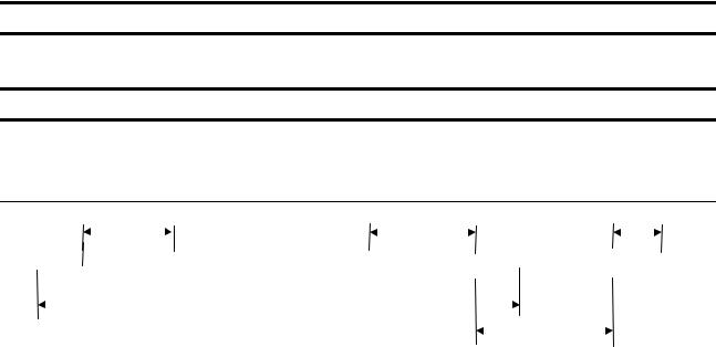
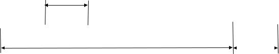
*The smallest unit of information that computers handle is called a “bit (binary digit),” which represents the two numbers in the binary system: 1 or 0. A group of 16 bits is referred to as a “word,” which is the basic unit of information the VF-S11 series of inverters use for data communications. One word can handle data items of 0 to FFFFH in hexadecimal notation (or 0 to 65535 in decimal notation).
BIT15 |
|
|
|
|
BIT8BIT7 |
|
|
|
|
BIT0 |
|||||
|
|
|
|
|
|
|
|
|
|
|
|
|
|
|
|
1 bit
1 word
3
E6581222
2. Data transmission specifications
|
Items |
Specifications |
|
|
|
|
|
||
Transmission scheme |
Half-duplex |
|
||
Synchronization scheme |
Start-stop synchronization |
*: Standard |
||
Communication baud rate |
1200/2400/4800/9600*/19200 bps (selectable using a parameter) *1 |
|||
default setting |
||||
Communication protocol |
TOSHIBA Inverter Protocol * / MODBUS-RTU |
|
||
Character transmission |
<ASCII mode> JIS X 0201 8-bit (ASCII) |
|
||
|
|
<Binary mode, MODBUS-RTU> Binary codes fixed to 8 bits |
|
|
Stop bit length |
Received by inverter: 1 bit, Sent by inverter: 2 bits *3 |
|
||
Error detecting scheme |
Parity *2: Even */odd/non parity (selectable using a parameter) *1, |
|
||
|
|
checksum(Toshiba inverter protocol), CRC(MODBUS-RTU) |
|
|
Character |
transmission |
11-bit characters *1 (Stop bit=1, with parity) |
|
|
format |
|
|
|
|
Order of bit transmission |
Low-order bits transmitted first |
|
||
Frame length |
Variable (to a maximum of 17 bytes) |
|
||
*1: Changes to the communication baud rate and to the parity setting do not take effect until the inverter is turned back on or reset.
*2: JIS-X-0201 (ANSI)-compliant 8-bit codes are used for all messages transmitted in ASCII mode and vertical (even) parity bits specified by JIS-X-5001 are added to them. These even parity bits can be changed to odd parity bits by changing the parameter setting (a change to the parameter setting does not take effect until the inverter has been reset.)
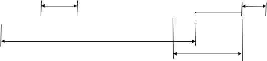
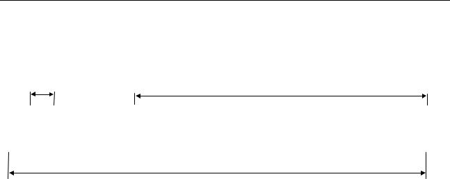
*3: Here are the default character transmission formats. (Standard default setting)
Characters received: 11 bits (1 start bit + 8 bits + 1 parity bit + 1 stop bit) ... Standard default setting
START |
|
|
|
|
|
|
|
|
PARITY |
STOP |
BIT |
BIT0 |
BIT1 |
BIT2 |
BIT3 |
BIT4 |
BIT5 |
BIT6 |
BIT7 |
BIT |
BIT |
The inverter receives one stop bit.
(The computer can be set so as to send 1, 1.5 or 2 stop bits.)
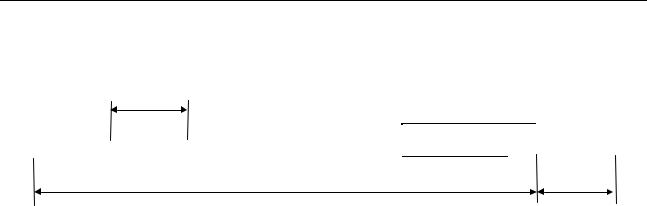
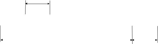
Characters sent: 12 bits (1 start bit + 8 bits + 1 parity bit + 2 stop bits) ... Standard default setting
START |
|
|
|
|
|
|
|
|
PARITY |
STOP |
STOP |
BIT |
BIT0 |
BIT1 |
BIT2 |
BIT3 |
BIT4 |
BIT5 |
BIT6 |
BIT7 |
BIT |
BIT |
BIT |
The inverter sends two stop bits.
(The computer can be set so as to receive 1, 1.5 or 2 stop bits.)
4

E6581222
3. Communication protocol
This communication protocol supports the TOSHIBA Inverter Protocol and part of MODBUS-RTU protocol.
Select the desired protocol from in the following communication protocol selection parameters ( ).
“Parameter Name , Communication Number. 0829” Data Range: 0, 1 (Initial value: 0)
0:TOSHIBA Inverter Protocol (Includes inter-drive communications)
1:MOUBUS-RTU protocol
*A parameter change is reflected when the inverter is reset, such as in power off.
Note : When using the extension panel (RKP001Z) and the parameter writer (PWU001Z), be certain to set F829=”0” : TOSHIBA inverter protocol.
5

E6581222
4. TOSHIBA Inverter Protocol
Select “TOSHIBA Inverter Protocol” ( = ) in the communication protocol selection parameters. “TOSHIBA Inverter Protocol” ( = ) is set for initial communication protocol selection of shipment setting. (See “3. Communication protocol.”)
■ Exchange of data between the computer and the inverter
In communications between the computer and the VF-S11 (hereinafter referred to as the inverter), the inverter is always placed in wait states and acts as a slave that operates on a request from the computer. A start code is used to automatically identify the mode in which data is transmitted: ASCII mode or binary mode.
A transmission error will result if the transmission format does not match.
■ ASCII mode
(1)In ASCII mode, the start code is “(”
The inverter rejects all data items entered invalid the “(” If two or more “(” are entered, the “(” entered last will be valid and all “(“ entered before will be ignored. If the “(” is not recognized because of a format error or for any other reason, no error code will be returned since the data is not recognized at all. In such cases, the inverter regards the data received as a transmission error, rejects it and goes back into a start code wait state.
(2)When an inverter number is added behind the “(” communications will take place only in case of broadcast communication or if the number matches up with that assigned to the inverters. If not, the inverter will go back into a start code wait state.
(3)The inverter stops receiving data on receipt of the CR (carriage return) code inserted in the designated position.
If the size of the data transmitted exceeds the maximum allowable size (17 bytes) or if the CR code cannot be found in the designated position within 0.5 seconds, the inverter will regard the data received as a transmission error and go back into a start code wait state.
(4)If no communications take place within the time specified using the timer function, the computer will regard it as a communication error and trip the inverter. The timer setting is cleared when the timer is turned on or initialized. For more details, see Section 7.3, “Timer function.”
(5)On executing the command received, the inverter returns data to the computer. For the response time, see Appendix 2, “Response time.”
6
E6581222
■ Binary mode
(1)In binary mode, the start code is “2FH(/).”
The inverter rejects all data items entered before the “2FH(/).”
If two or more “2FH(/)” are entered, the “2FH(/)” entered last will be judged valid and all “2FH(/)” entered before will be ignored.
If the “2FH(/)” is not recognized because of a format error or for any other reason, no error code will be returned since the data is not recognized at all. In such cases, the inverter regards the data received as a transmission error, rejects it and goes back into a start code wait state.
(2)If an inverter number is added behind the “2FH(/),” communications will take place only in case of broadcast communication or if the number matches up with that assigned to the inverters. If not, the inverter will go back into a start code wait state.
(3)The inverter stops receiving data on receipt of a command and the number of bytes of data specified by the command.
If no command is found in the data received or if the specified number of bytes of data cannot be received within about 0.5 seconds, the inverter will regard the data received as a transmission error and go back into a start code wait state.
(4)If no communications take place within the time specified using the timer function, the computer will assume that a communication error has occurred and trip the inverter. The timer function is disabled when the inverter is turned on or initialized. For details, see Section 7.3, “Timer function.”
(5)On executing the command received, the inverter returns data to the computer. For the response time, see Appendix 2, “Response time.”
■ Note
Communication is not possible for about one second after the power is supplied to the inverter until the initial setting is completed. If the control power is shut down due to an instantaneous voltage drop, communication is temporarily interrupted.
7
E6581222
4.1. Data transmission formats
■ Note: The term “trip status” used in this manual includes retry waiting status and trip retention status.
4.1.1. Data transmission formats used in ASCII mode
A communication number is used to specify a data item, all data is written in hexadecimal, and JIS- X-0201 (ASCII (ANSI))-compliant transmission characters are used.
■ Computer → VF-S11
Omissible in one-to-one communications |
For the W and P commands only |
|
Omissible |
|
||||||||||||||||||
|
|
|
|
|
|
|
|
|
|
|
|
|
|
|
|
|
|
|
|
|
||
|
|
|
|
|
|
|
|
|
|
|
|
|
|
|
|
|
|
|
|
|
|
|
|
"(" |
|
INV-NO |
|
CMD |
|
Communication No. |
|
DATA |
"&" |
|
SUM |
|
|
")" |
|
CR |
|||||
|
(28H) |
|
2 bytes |
|
1 byte |
|
|
4 bytes |
|
0 to 4 bytes |
(26H) |
2 bytes |
|
|
|
(29H) |
(0DH) |
|||||
|
|
|
|
|
|
|
Checksum area |
|
|
|
|
|
|
|
|
|
|
|
|
|
||
|
|
|
|
|
|
|
|
|
|
|
|
|
|
|
|
Omissible |
|
|
|
|
|
|
|
|
1. “(“ (1 byte) |
: Start code in ASCII mode |
|
|
|
|
|
|
|
|
|
|
|
|
|
||||||
2. INV-NO (2 bytes) : Inverter number (Omissible in one-to-one communications) ... 00 (30H, 30H) to 99 (39H, 39h), *(2AH)
The command is executed only when the inverter number matches up with that specified using a parameter.
(When * is specified in broadcast communications, the inverter number is assumed to match if all numbers except * match. When * is specified instead of each digit (two-digit number), all inverters connected are assumed to match.)
If the inverter number does not match or if the inverter number is of one digit, the data will be judged invalid and no data will be returned.
3. CMD (1 byte) |
: Command (For details, see the table below.) |
4.Communication No.(4 bytes)
:Communication number (See 11, “Parameter data.”)
5.Data (0 to 4 bytes): Write data (valid for the W and P commands only)
6. |
“&” (1 byte) |
: Checksum discrimination code (omissible. When omitting this code, you also need to omit |
|
|
the checksum.) |
7. |
Sum (2 bytes) |
: Checksum (omissible) |
|
|
Add the ASCII-coded value of the last two digits (4 bits/digit) of the sum of a series of bits |
|
|
(ASCII codes) from the start code to the checksum discrimination code. |
|
|
Ex.: (R0000&??) CR |
|
|
28H+52H+30H+30H+30H+30H+26H=160H |
|
|
The last two digits represent the checksum. = 60 |
|
|
When omitting the checksum, you also need to omit the checksum discrimination code. |
8. |
“)” (1 byte) |
: Stop code (omissible) |
9. |
CR (1 byte) |
: Carriage return code |
■ Details of commands and data
CMD (1 byte) |
Write data (0 to 4 bytes) Hexadecimal number |
R (52H): RAM read command |
No data |
W (57H): RAM/EEPROM write command |
Write data (0 to FFFF) |
P (50H) RAM write command |
Write data (0 to FFFF) |
8
E6581222
■ VF-S11 → computer
At time of broadcast communication, returning of data is not executed, except for the inverters to be returned, when the inverter number is not matched, and the inverter number has only one character. This is because there will be a risk of that the returned data may be deformed.
• Data returned when data is processed normally (ASCII mode) |
|
|
|
|
|
|
|
|
|
|
|
|
|||||||||
|
|
|
|
Omissible |
|
|
|
|
|
|
|
|
|
|
|
Omissible |
|||||
|
|
|
|
|
|
|
|
|
|
|
|
|
|
|
|
|
|
|
|
|
|
|
|
|
|
|
|
|
|
|
|
|
|
|
|
|
|
|
|
|
|
|
|
|
|
|
"(" |
INV-NO |
|
CMD |
|
Communication No. |
|
DATA |
"&" |
|
|
SUM |
|
")" |
|
CR |
|
||
|
(28H) |
2 bytes |
|
1 byte |
|
4 bytes |
|
0 to 4 bytes |
(26H) |
|
2 bytes |
|
|
(29H) |
(0DH) |
|
|||||
|
|
|
|
|
|
|
Checksum area |
|
|
|
|
|
|
|
|
|
|
|
|
||
|
|
|
|
|
|
|
|
|
|
|
|
|
|
Omissible |
|
|
|
|
|
|
|
1. |
“(“ (1 byte) |
: Start code in ASCII mode |
|
|
|
|
|
|
|
|
|
|
|
|
|||||||
2. |
INV-NO (2 bytes) |
: Inverter number (omitted if it is not found in the data received) ... 00 (30H, 30H) to 99 (39H, |
|||||||||||||||||||
|
|
|
|
|
|
39H) |
|
|
|
|
|
|
|
|
|
|
|
|
|
|
|
|
|
|
|
|
|
If the inverter number matches up with that specified using a parameter, data will be return- |
|||||||||||||||
|
|
|
|
|
|
ed to the computer. In broadcast communications, only the destination inverter (with a num- |
|||||||||||||||
|
|
|
|
|
|
ber matching up with the smallest effective number) returns data to the computer. |
|
|
|||||||||||||
|
|
|
|
|
|
In broadcast communications, no data is returned from any inverters except the inverter |
|||||||||||||||
|
|
|
|
|
|
bearing a number that matches up with the smallest effective number. |
|
|
|
|
|
|
|||||||||
|
|
|
|
|
|
Ex.: (*2R0000) CR -> (02R00000000) CR) |
|
|
|
|
|
|
|
|
|
|
|
||||
|
|
|
|
|
|
Data is returned from the inverter with the number 2 only, but no data is returned from |
|||||||||||||||
|
|
|
|
|
|
inverters with the number 12, 22 .... |
|
|
|
|
|
|
|
|
|
|
|
||||
3. |
CMD (1 byte) |
: Command ... The command is also used for a check when an inverter is tripped. |
|
|
|||||||||||||||||
|
|
|
|
|
|
Under normal conditions... The uppercase letter R, W or P is returned, depending on the |
|||||||||||||||
|
|
|
|
|
|
command received: R, W or P command. |
|
|
|
|
|
|
|
|
|
|
|
||||
|
|
|
|
|
|
When an inverter is tripped... The lowercase letter r, w or p is returned, depending on the |
|||||||||||||||
|
|
|
|
|
|
command received: R, W or P command. |
|
|
|
|
|
|
|
|
|
|
|
||||
|
|
|
|
|
|
(The command received is returned with 20H added to it.) |
|
|
|
|
|
|
|
|
|||||||
4. |
Communication No.(4 bytes) : |
|
|
|
|
|
|
|
|
|
|
|
|
||||||||
|
|
|
|
|
|
The communication number received is returned. |
|
|
|
|
|
|
|
|
|
|
|
||||
5. |
Data (0 to 4 bytes): Data ... The data read in is returned for the R command, while the data received is returned |
||||||||||||||||||||
|
|
|
|
|
|
for the W and P commands. If the data received is composed of less than 4 digits, it will be |
|||||||||||||||
|
|
|
|
|
|
converted into 4-digit data and returned. |
|
|
|
|
|
|
|
|
|
|
|
||||
|
|
|
|
|
|
Ex.: (W123412) CR → (W12340012) CR) |
|
|
|
|
|
|
|
|
|
|
|
||||
6. |
“&” (1 byte) |
: Checksum discrimination code (omitted if it is not found in the data received) |
|
|
|||||||||||||||||
7. |
Sum (2 bytes) |
: Checksum ... Omitted if no checksum discrimination code is found in the data received. |
|||||||||||||||||||
|
|
|
|
|
|
ASCII-coded value of the last two digits (4 bits/digit) of the sum of a series of bits (ASCII |
|||||||||||||||
|
|
|
|
|
|
codes) from the start code to the checksum discrimination code. |
|
|
|
|
|
|
|||||||||
8. |
“)” (1 byte) |
: Stop code (omitted if it is not found in the data received) |
|
|
|
|
|
|
|
|
|||||||||||
9. |
CR (1 byte) |
: Carriage return code |
|
|
|
|
|
|
|
|
|
|
|
|
|||||||
9
E6581222
• Data returned when data is not processed normally (ASCII mode)
In case an error occurs, communication error command (4EH(N) or 6EH(n)) and the error type number is returned to the computer in addition to the checksum. At time of broadcast communication of the binary mode, returning of data is not executed except for the inverter to be returned (inverter number 00H) and when the inverter number is not matched. This is because there will be a risk that the returned data may be deformed.
|
|
Omissible |
|
|
|
|
|
|
Omissible |
|
|
|||||
|
|
|
|
|
|
|
|
|
|
|
|
|
|
|
|
|
|
“(“ |
|
INV-NO |
|
“N” or “n” |
|
DATA |
"&" |
|
SUM |
|
")" |
|
CR |
|
|
|
(28H) |
|
2 bytes |
|
(4EH) |
(6EH) |
|
4 bytes |
(26H) |
|
2 bytes |
|
(29H) |
|
(0DH) |
|
|
|
|
|
Checksum area |
|
|
|
|
|
|
|
|
|
|||
|
|
|
|
|
|
|
|
|
|
Omissible |
|
|
|
|
|
|
|
“(“ (1 byte) |
: Start code in ASCII mode |
|
|
|
|
|
|
|
|
|
|||||
1) N or n (1 byte) |
:Communication error command ... This is also used for the checking of inverter trip. |
|||||||||||||||
|
“4EH(N)” for the normal communication and “6EH(n)” during the inverter trip. |
Data (4 bytes) |
: Error code (0000~0004) |
|
0000 ... Impossible to execute (Although communication is established normally, the com- |
|
mand cannot be executed because it is to write data into a parameter whose set- |
|
ting cannot be changed during operation (e.g., maximum frequency) or the |
|
EEPROM is faulty.) |
|
0001 ... Data error (The data is outside the specified range or it is composed of too many |
|
digits.) |
|
0002 ... Communication number error (There is no communication number that matches.) |
|
0003 ... Command error (There is no command that matches.) |
|
0004 ... Checksum error (The checksum result differs.) |
“)” (1 byte) |
: Stop code ... This code is omitted if it is not found in the data received. |
■ Examples:
(N0000&5C)CR... Impossible to execute (e.g., a change of maximum frequency data during operation)
(N0001&5D)CR... Data error (Data is outside the specified range.)
(N0002&5E)CR... No communication number (There is no communication number that matches.) (N0003&5F)CR... There is no command that matches. (Commands other than the R, W and P com-
mands)
(Ex.: L, S, G, a, b, m, r, t, w ...) (N0004&60)CR... Checksum error (The checksum result differs.) No data returned ... Format error or invalid inverter number
(Ex.: A code other than the stop code (“)”) (Ex.: ””) is entered in the stop code position or the CR code was not found within 0.5 sec.)
10

E6581222
4.1.2. Data transmission formats used in binary mode
A communication number is used to specify a data item, data is written in hexadecimal form, and data in transmission characters are represented by binary codes (HEX codes).
■ Computer → VF-S11 (binary mode)
Omissible in one-to-one communications |
No data for the 52H (R) command |
||||||
|
|
|
|
|
|
|
|
“/” |
INV-NO |
CMD |
|
Communication No. |
DATA |
SUM |
|
(2FH) |
1 byte |
1 byte |
|
2 bytes |
|
2 bytes |
1 byte |
|
|
|
Checksum area |
|
|
Not omissible |
|
1. 2FH (“/”) (1 byte) : Start code in binary mode
2. INV-NO (2 bytes) : Inverter number (Omissible in one-to-one communications) ... 00H to 3FH ,FFH
|
In case the inverter number is other than FFH (broadcast communication), command is ex- |
|
ecuted only when the inverter number coincides with the one designated with the panel. If |
|
the inverter number is not matched, it will be judged invalid and the data is not returned. |
3. CMD (1 byte) |
: Command (For details, see the table below.) |
|
52H (R) command: The size of the data following CMD is fixed to 3 bytes. (Communication |
|
number: 2 bytes, checksum: 1 byte) |
|
57H (W), 50H (P) and 47H (G) commands: The size of the data following CMD is fixed to 5 |
|
bytes. |
|
(Communication number: 2 bytes, data: 2 byte, checksum: 1 byte) |
|
Any command other than the above is rejected and no error code is returned. |
4.Communication No.(2 bytes)
:Communication number (See 11, “Parameter data.”)
5. Data (2 bytes) |
: 0000H to FFFFH |
|
|
57H |
(W) and 50H (P) commands: Write data (An area check is performed.) |
|
47H |
(G) command: Dummy data (e.g., 0000) is needed. |
|
52H |
(R) command: Any data is judged invalid. (No data should be added.) |
6. Sum (2 bytes) |
: Checksum (not omissible) 00H to FFH |
|
|
Value of the last two digits (1 byte) of the sum of a series of bits (codes) from the start code |
|
|
of the data returned to the data (or to the communication number for the 52H (R) command) |
|
|
Ex.: 2F 52 00 ?? ... 2FH+52H+00H+00H=81H |
|
|
The last two digits (??) represent the checksum. = 81 |
|
■ Details of commands and data
CMD (1 byte) |
Write data (2 bytes) Hexadecimal number |
|
52H |
(R): RAM read command |
No data |
57H |
(W): RAM/EEPROM write command |
Write data (0000H to FFFFH) |
50H |
(P): RAM write command |
Write data (0000H to FFFFH) |
47H |
(G): RAM read command (for two-wire networks) |
Dummy data (0000H to FFFFH) |
11
E6581222
■ VF-S11 → computer (binary mode)
At time of broadcast communication of the binary mode, returning of data is not executed except for the inverter to be returned (inverter number 00H) and when the inverter number is not matched. This is because there will be a risk that the returned data may be deformed.
• Data returned when data is processed normally (Binary mode)
|
Omissible |
|
|
|
|
|
|
|
|
|
|
|
|
|
|
“/” |
INV-NO |
CMD |
|
Communication No. |
DATA |
SUM |
|
(2FH) |
1 byte |
1 byte |
|
2 bytes |
2 bytes |
1 byte |
|
|
|
|
Checksum area |
|
|
Not omissible |
|
1. 2FH (“/“) (1 byte) : Start code in binary mode
2. INV-NO (2 bytes) : Inverter number... 00H to 3FH (The inverter number is omitted if it is not found in the data received.)
If the inverter number matches up with that specified from the operation panel, data will be returned from the inverter. If the inverter number does not match, the data will be invalid and no data will be returned.
3. CMD (1 byte) |
: Command...The command is also used for a check when the inverter is tripped. |
|
Under normal conditions...52H (R), 47H (G), 57H (W) or 50H (P) is returned, depending on |
|
the command received. |
|
When the inverter is tripped...The lowercase letter 72H (r), 67H (g), 77H (w) or 70H (p) is |
|
returned with 20H added to it, depending on the command received. |
4.Communication No. (4 bytes)
:The communication number received is returned.
5. |
Data (2 bytes) |
: Data ... 0000H to FFFFFH |
|
|
The data read is returned for the 52H (R) and 47H (G) commands, while the data written is |
|
|
returned for the 57H (W) and 50H (P) commands. |
6. |
Sum (1 bytes) |
: Checksum (not omissible) 00H to FFH |
|
|
Value of the last two digits (1 byte) of the sum of a series of bits (codes) from the start code |
|
|
to the data. |
12
E6581222
2) Error Processing (Binary mode)
In case an error occurs, communication error command (4EH(N) or 6EH(n)) and the error type number is returned to the computer in addition to the checksum. At time of broadcast communication of the binary mode, returning of data is not executed except for the inverter to be returned (inverter number 00H) and when the inverter number is not matched. This is because there will be a risk that the returned data may be deformed.
|
Omissible |
|
|
|
|
|
|
|
(1 byte) |
|
|
(1 byte) |
|
|
|
|
|
“/” |
INV-NO |
|
N or n |
DATA |
|
SUM |
|
|
(2FH) |
1 byte |
|
(4EH)(6EH) |
2 bytes |
|
1 byte |
|
|
|
|
Checksum area |
|
|
Not omissible |
|
||
N or n (1 byte) |
: Communication error command ... This command is also used for a check when the inverter |
|||||||
|
is tripped. |
|
|
|
|
|
||
|
“4EH (N)” is returned under normal conditions, while “6EH (n)” is returned when the in- |
|||||||
|
verter is tripped. |
|
|
|
|
|
||
Data (2 bytes) |
: Error code (0000~0004) |
|
|
|
|
|
||
|
0000 |
... Impossible to execute (Although communication is established normally, the com- |
||||||
|
|
|
mand cannot be executed because it is to write data into a parameter whose setting |
|||||
|
|
|
cannot be changed during operation (e.g., maximum frequency) or the EEPROM is |
|||||
|
|
|
faulty.) |
|
|
|
|
|
|
0001 |
... Data error (The data is outside the specified range or it is composed of too many |
||||||
|
|
|
digits.) |
|
|
|
|
|
|
0002 |
... Communication number error (There is no communication number that matches.) |
||||||
|
0004 |
... Checksum error (The checksum result differs.) |
|
|
|
|
||
No code returned ...Command error, format error (failure to receive the specified number of bytes within 0.5 seconds, or an parity, overrun or framing error) or the inverter number does not match or an inverter in broadcast communication in the binary mode except for the inverter for data returning (the inverter numbered 00H).
■ Examples:
2FH, 4EH, 00H, 00H, 7DH ... Impossible to execute (e.g., a change of maximum frequency data during operation)
2FH, 4EH, 00H, 01H, 7EH ... Data setting error (The data specified falls outside the specified range.)
2FH, 4EH, 00H, 02H, 7FH ... No communication number (There is no communication number that matches.)
2FH, 4EH, 00H, 04H, 81H ... Checksum error (The checksum result differs.)
13

E6581222
4.1.3. Transmission Format of Block Communication
What is block communication?
Data can be written in and read from several data groups set in one communication by setting the type of data desired for communication in the block communication parameters ( , ,to ) in advance. Block communications can save the communication time.
Data is transmitted hexadecimal using the binary (HEX) code transmission characters. “Computer
→inverter” is for writing only, while “Inverter → computer” for reply is for reading only.
■Computer → VF-S11 (Block Communications)
|
Omissible |
|
|
Number of writing data groups x 2 bytes |
|
|||||||
|
|
|
|
|
|
|
|
|
|
|
|
|
|
|
|
|
|
|
|
|
|
|
|
|
|
|
|
|
|
|
|
|
|
|
|
|
|
|
Start |
|
INV-NO |
CMD |
Num- |
Num- |
|
Write |
Write |
Write |
Write |
SUM |
|
Code |
|
|
|
“X” |
ber of |
ber of |
|
data1 |
data1 |
data2 |
data2 |
|
|
|
|
write |
read |
|
|
||||||
“ ” |
|
|
|
|
|
High |
Low |
High |
Low |
|
||
|
|
|
|
data |
data |
|
|
|||||
|
|
|
|
|
|
|
|
|
|
|
||
|
|
|
|
|
groups |
groups |
|
|
|
|
|
|
Checksum Area
1.2FH(“/”) (1 byte) : Start code of binary mode
2.INV-NO (1 byte) : Inverter number. (Can be omitted in 1:1 communications): 00H to 3FH, FFH
Executed only when the inverter number matches the inverter number. Set on the panel, except in FFH (broadcast communication).
Communication data will be invalidated and data will not be returned either if the inverter number. Does not match.
3. CMD (1 byte) : ‘X’ (Block communication command)
4.Number of write data groups (1 byte)
:Specify the number of data groups to be written (00H to 02H).
If specified outside of the range, data will be treated as a format error and data will not be returned.
5.Number of read data groups (1 byte)
:Specify the number of data groups to be read (00H to 05H).
If specified outside of the range, data will be returned as “Number of read data groups = 0” when returned by the inverter.
6.Write data1 (2 bytes)
:Needed when the number of write data groups is larger than 1. Data to be written to the specified parameter selected by
Dummy data is needed if the number of write data groups is larger than 1 even though(none) is selected for
7.Write data2 (2 bytes)
:Needed when the number of write data groups is 2.
Data to be written to the specified parameter selected by
Dummy data is needed if the number of write data groups is 2 even though(none) is selected for
8. SUM (1 byte) : Checksum (Cannot be omitted) 00H to FFH
Lower two digits (1 byte) of total sum from start code (SUM value not included)
14

E6581222
■ Block Write 1, 2
Select data, which is desired to be written in block communications, in Block Communication Write Data 1 and 2 Parameters ( , ). This parameter becomes effective when the system is reset, such as when power is turned off. When the setting is completed, turn off and then on the power.
No. |
Block Write Data |
For data details, see: |
|
0 |
No selection |
|
|
1 |
Command 1 (FA00) |
“8.1 Command by communication” |
|
2 |
Command 2 (FA20) |
“8.1 Command by communication” |
|
3 |
Frequency Command Value (FA01) |
“8.1 Command by communication” |
|
4 |
Terminal Board Output Data (FA50) |
“8.3 Control of input/put signals from com- |
|
munication” |
|||
|
|
||
5 |
Communication Analog Output (FA51) |
“8.3 Control of input/put signals from com- |
|
munication” |
|||
|
|
*When “No selection” is specified in the parameters, no data will be written even though write data is specified.
■Block Read 1 to 5
Select read data, which is desired to be read in block communications, in Block Communication Read Data 1 and 5 Parameters ( to ). This parameter becomes effective when the system is reset, such as when power is turned off. When the setting is completed, turn off and then on the power.
No. |
Block Read Data |
For data details, see: |
|
|
|
0 |
No selection |
|
|
|
|
1 |
Status 1 (FD01) |
“8.2 Monitoring from communication” |
|||
2 |
Output Frequency (FD00) |
“8.2 Monitoring from communication” |
|||
3 |
Output Current (FE03) |
“9. Parameter data” |
|
|
|
4 |
Output Voltage (FE05) |
“9. Parameter data” |
|
|
|
5 |
Alarm Information (FC91) |
“8.2 Monitoring from communication” |
|||
6 |
PID Feedback Value (FE22) |
“9. Parameter data” |
|
|
|
7 |
Input Terminal Board Monitoring (FD06) |
“8.3 Control of |
input/put |
signals |
from |
communication” |
|
|
|
||
|
|
|
|
|
|
8 |
Output Terminal Board Monitoring (FD07) |
“8.3 Control of |
input/put |
signals |
from |
communication” |
|
|
|
||
|
|
|
|
|
|
9 |
Analog Monitoring VIA (FE35) |
“8.3 Control of |
input/put |
signals |
from |
communication” |
|
|
|
||
|
|
|
|
|
|
10 |
Analog Monitoring VIB (FE36) |
“8.3 Control of |
input/put |
signals |
from |
communication” |
|
|
|
||
|
|
|
|
|
|
*Output current (FE03), output voltage (FE05) and PID feedback value (FE22) will become hold data during a trip. Otherwise, real-time data appears.
*“0000” will be returned as dummy data, if “0 (No selection)” is selected for the parameter and “read” is specified.
15
E6581222
■ VF-S11 → Computer
At time of broadcast communication of the binary mode, returning of data is not executed except for the inverter to be returned (inverter number 00H) and when the inverter number is not matched. This is because there will be a risk that the returned data may be deformed.
1) Normal processing
Omissible |
|
|
|
|
Number of read data groups x 2 bytes |
|
|
|
|||||||
|
|
|
|
|
|
|
|
|
|
||||||
|
|
|
|
|
|
|
|
|
|
|
|
|
|
|
|
Start |
INV |
CMD |
Number |
Write |
Read |
Read |
Read |
Read |
Read |
Read |
Read |
Read |
Read |
Read |
SUM |
Code |
No. |
“Y” |
of Read |
Status |
data1 |
data1 |
data2 |
data2 |
data3 |
data3 |
data4 |
data4 |
data5 |
data5 |
|
“ ” |
|
|
Data |
|
high |
low |
high |
low |
high |
low |
high |
low |
high |
low |
|
|
|
|
Groups |
|
|
||||||||||
|
|
|
|
|
|
|
|
|
|
|
|
|
|
|
|
Checksum area
1.2FH “/” (1 byte) Start code in binary mode
2.INV-NO (1Byte) Inverter number 00H to 3FH
If the inverter number matches up with that specified from the operation panel, data will be returned from the inverter. If the inverter number does not match, the data will be judged invalid and no data will be returned.
Communication data will be invalidated and data will not be returned either if the inverter number does not match. (Inverter number is considered matched if it is omitted during reception)
3. CMD(1Byte) |
:‘Y’ (Block communication command [monitoring]) |
|
Lowercase letter ‘y’ during an inverter trip, including standing by for retrying and during |
atrip.
4.Number of read data groups (1 byte)
:Return the number of data groups to be read (00H to 05H).
5. Write status (1 byte) : Return 00H to 03H.
* Failing to write in the specified parameter in the number of write data groups, set “1” in the corresponding bit for the parameter failed to write. (See below.)
Bit Position |
7 |
6 |
5 |
|
4 |
3 |
2 |
1 |
0 |
Data Type |
|
|
|
|
|||||
6.Read data1 - 5 (2 bytes)
:Return according to the number of read data groups. “0000H” is returned as dummy
data if “0” is selected as a parameter.
Read data1: Data selected by . Read data2: Data selected by .
|
Read data3: Data selected by . Read data4: Data selected by . |
|
Read data5: Data selected by . |
7.SUM(1Byte) |
: Checksum (Cannot be omitted) 00H to FFH |
|
Lower two digits (1 byte) of total sum from start code of return data to read data. |
■ Example
(When set as follows: = (Command 1), = (frequency command value),
= (status), = (output frequency), = (output current), = (output voltage) and= (alarm)
Computer → Inverter 2F 58 02 05 C4 00 17 70 D9
Inverter → Computer 2F 59 05 03 00 00 00 00 00 00 00 00 00 00 90 (When parameter is not set) Inverter → Computer 2F 59 05 00 40 00 00 00 00 00 00 00 00 00 CD CD (When parameter is set) Inverter → Computer 2F 59 05 00 64 00 17 70 1A 8A 24 FD 00 00 3D (During operation at 60Hz)
16
E6581222
2) Error Processing (Binary mode)
In case an error occurs, communication error command (4EH(N) or 6EH(n)) and the error type number is returned to the computer in addition to the checksum. At time of broadcast communication of the binary mode, returning of data is not executed except for the inverter to be returned (inverter number 00H) and when the inverter number is not matched. This is because there will be a risk that the returned data may be deformed.
|
|
|
|
Omissible |
|
|
|
|
|
|
|
|
|
|
(1 Byte) |
|
(1 Byte) |
|
|
|
|
|
|
||
|
|
|
|
|
|
|
|
|
|
|
|
|
|
|
“ ” |
|
INV-NO |
“N” or “n” |
|
DATA |
|
SUM |
|
||
|
|
(2FH) |
|
1 Byte |
(4EH)(6EH) |
|
2 Bytes |
|
1 Byte |
|
||
|
|
|
|
|
|
|
|
|
|
|
|
|
|
|
|
|
|
Checksum Area |
|
|
|
Not omissible |
|||
|
|
|
|
|
|
|
||||||
|
“N” or “n” (1 byte) : Communication error command. |
Also for check during an inverter trip (includes standing by |
||||||||||
|
|
|
|
for retrying and trip holding). “4EH (N)” when normal, “6EH (n)” during an inverter trip. |
||||||||
|
DATA (2 bytes) |
: Error code (0004) |
|
|
|
|
|
|
||||
|
|
|
|
0004 |
: Checksum error (The checksum does not match) |
|
|
|
|
|||
|
|
|
|
No return : Command error, format error (specified number of bytes is not received in 1sec, |
||||||||
|
|
|
|
|
or parity error, overrun error or framing error), inverter number mismatch, and |
|||||||
|
|
|
|
|
inverter number other than 00H in broadcast communication. |
|||||||
■ Examples |
|
|
|
|
|
|
|
|
|
|||
Computer → Inverter |
: 2F 58 02 05 C4 00 17 70 D8 |
|
|
|
|
|
|
|||||
Inverter → Computer |
: 2F 4E 00 04 81 ... Checksum error |
|
|
|
|
|
|
|||||
17

E6581222
4.2. Commands
Here are the communication commands available.
Command |
Function |
|
R command |
Reads the data with the specified communication number. |
|
W command |
Writes the data with the specified communication number. (RAM and EEPROM). |
|
P command |
Writes the data with the specified communication number. (RAM). |
|
G command |
Reads the data with the specified communication number. (For binary mode only. |
|
Dummy data is required for this command.) |
||
|
||
X command |
Block communication (Computer -> Inverter) |
|
Y command |
Block communication (Inverter -> Computer) |
W (57H) (RAM*1 /EEPROM*2 write)
This command is used to write new data into the parameter specified using it communication number. It writes data into the RAM and EEPROM. For parameters whose settings cannot be stored in the EEPROM (e.g., parameter with the communication number FA00), the W (57H) command writes data into the RAM only. It cannot be used to write data into read-only parameters (e.g., parameter with the communication number FD?? or FE??).
Each time an attempt to write data is made, the inverter checks if the data falls within the specified range. If this check reveals that the data falls outside the specified range, the inverter will reject it and return an error code.
- Ex.: Setting the deceleration time (communication number: 0010) to 10 sec.
<ASCII mode> |
|
CR: Carriage return |
Computer → Inverter |
Inverter → Computer |
|
(W00100064)CR |
(W00100064)CR |
…(10÷0.1=100=0064H) |
<Binary mode> |
|
|
Computer → Inverter |
Inverter → Computer |
|
2F 57 00 10 00 64 FA |
2F 57 00 10 00 64 FA |
…(10÷0.1=100=0064H) |
Notice
♦Do not write the same parameter to the EEPROM more than 10,000 times. The life time of EEPROM is approximately 10,000 times.(Some parameters are not limited, please refer to the “9.Parameter data “) The lifetime of EEPROM is approximately 10,000 times. When using the TOSHIBA inverter protocol and the data does not need to be records, use P command (the data is written only to RAM).
■Explanation of terms
*1: The RAM is used to temporarily store inverter operation data. Data stored in the RAM is cleared when the inverter is turned off, and data stored in the EEPROM is copied to the RAM when the inverter is turned back on.
*2: The EEPROM is used to store inverter operation parameter settings, and so on. Data stored in the EEPROM is retained even after the power is turned off, and it is copied to the RAM when the inverter is turned on or reset.
18
E6581222
P (50H) (RAM*1 write)
This command is used to rewrite data into the parameter specified using a communication number. It writes data into the RAM only. It cannot be used to write data into any read-only parameters. Each time an attempt to write data is made the inverter checks whether the data falls within the specified range. If this check reveals that the data falls outside the range, the inverter will reject it and return an error code.
- Ex.: Entering the emergency stop command (communication number: FA00) from the computer
<ASCII mode> |
|
|
Computer → Inverter |
Inverter → Computer |
|
(PFA009000)CR |
(PFA009000)CR |
…Command priority, emergency stop |
|
|
command |
<Binary mode> |
|
|
Computer → Inverter |
Inverter → Computer |
|
2F 50 FA 00 90 00 09 |
2F 50 FA 00 90 00 09 |
|
R (52H) (Data read)
This command is used to read the setting of the parameter specified using a communication number. (When multiple inverters are operated in binary mode via RS485 converter connected to a two-wire line, the execution of the R command could result in a communication error. To avoid this, use the G command in binary mode when inverters are connected to a two-wire line.)
- Ex.: Monitoring the electric current (communication number: FE03) <ASCII mode>
Computer → Inverter |
Inverter → Computer |
|
(RFE03)CR |
(RFE03077B)CR |
…Current: 1915 / 100 = 19.15% |
<Binary mode> |
|
|
Computer → Inverter |
Inverter → Computer |
|
2F 52 FE 03 82 |
2F 52 FE 03 07 7B 04 |
|
Notice
When multiple inverters are operated in binary mode via RS485 converter connected to a two-wire line, use the G command to read data.
G (47H) (Data read)
This command is used to read the parameter data specified using a communication number.
To send this command to an inverter with two-wire type RS485 network, 2bytes of dummy data are needed. This command is available only in binary mode.
- Ex.: Monitoring the electric current (communication number: FE03)
Computer → Inverter |
Inverter → Computer |
2F 47 FE 03 00 00 77 |
2F 47 FE 03 07 7B F9 |
* In this example, the data 00H sent from the computer to the inverter is dummy data.
19
 Loading...