


 Loading...
OWNER’S MANUAL
3LCD DATA PROJECTOR
TLP380
TLP381 (WITH DOCUMENT IMAGING CAMERA)
MENU |
CONTENTS |
1
use Before
TLP380

 SAFETY PRECAUTIONS
CONTENTS |
2 |
WARNING: TO REDUCE THE RISK OF FIRE OR ELECTRIC SHOCK, DO NOT EXPOSE THIS APPLIANCE TO RAIN OR MOISTURE. DANGEROUS HIGH VOLTAGES ARE PRESENT INSIDE THE ENCLOSURE. DO NOT OPEN THE CABINET. REFER SERVICING TO QUALIFIED PERSONNEL ONLY.
use Before
The lightning flash with arrowhead symbol, within an equilateral triangle, is intended to alert the user to the presence of uninsulated “dangerous voltage” within the product’s enclosure that may be of sufficient magnitude to constitute a risk of electric shock to persons.
The exclamation point within an equilateral triangle is intended to alert the user to the presence of important operating and maintenance (servicing) instructions in the literature accompanying the appliance.
IMPORTANT PRECAUTIONS |
CONTENTS |
3 |
Save Original Packing Materials
The original shipping carton and packing materials will come in handy if you ever have to ship your LCD projector. For maximum protection, repack the set as it was originally packed at the factory.
Avoid Volatile Liquid
Do not use volatile liquids, such as an insect spray, near the unit. Do not leave rubber or plastic products touching the unit for a long time. They will mar the finish.
In the spaces provided below, record the Model and Serial No. located at the bottom of your LCD projector.
Model No. |
|
Serial No. |
|
Retain this information for future reference.
Moisture Condensation
Never operate this unit immediately after moving it from a cold location to a warm location. When the unit is exposed to such a change in temperature, moisture may condense on the crucial internal parts. To prevent the unit from possible damage, do not use the unit for at least 2 hours when there is an extreme or sudden change in temperature.
Exemption Clauses
•Toshiba Corporation bears no responsibility in the case of damages arising from earthquakes, fire not liable to Toshiba Corporation, operating by third parties, other accidents, or use under abnormal conditions including erroneous or improper operation and other problems.
•Toshiba Corporation bears no responsibility for incidental damages (lost profit, work interruption, corruption or loss of the memory contents, etc.) arising from the use of or the inability to use this unit.
•Toshiba Corporation accepts no liability whatsoever for any damages arising from not having followed the descriptions in this Owner’s Manual.
•Toshiba Corporation accepts no liability whatsoever for any damages arising from malfunctions arising from combination with equipment or software that is not related to Toshiba Corporation.
use Before

 IMPORTANT SAFETY INSTRUCTIONS
CONTENTS |
4 |
CAUTION: PLEASE READ AND OBSERVE ALL WARNINGS AND INSTRUCTIONS GIVEN IN THIS OWNER’S MANUAL AND THOSE MARKED ON THE UNIT. RETAIN THIS BOOKLET FOR FUTURE REFERENCE.
This set has been designed and manufactured to assure personal safety. Improper use can result in electric shock or fire hazard. The safeguards incorporated in this unit will protect you if you observe the following procedures for installation, use and servicing. This unit is fully transistorized and does not contain any parts that can be repaired by the user.
DO NOT REMOVE THE CABINET COVER, OR YOU MAY BE EXPOSED TO DANGEROUS VOLTAGE. REFER SERVICING TO QUALIFIED SERVICE PERSONNEL ONLY.
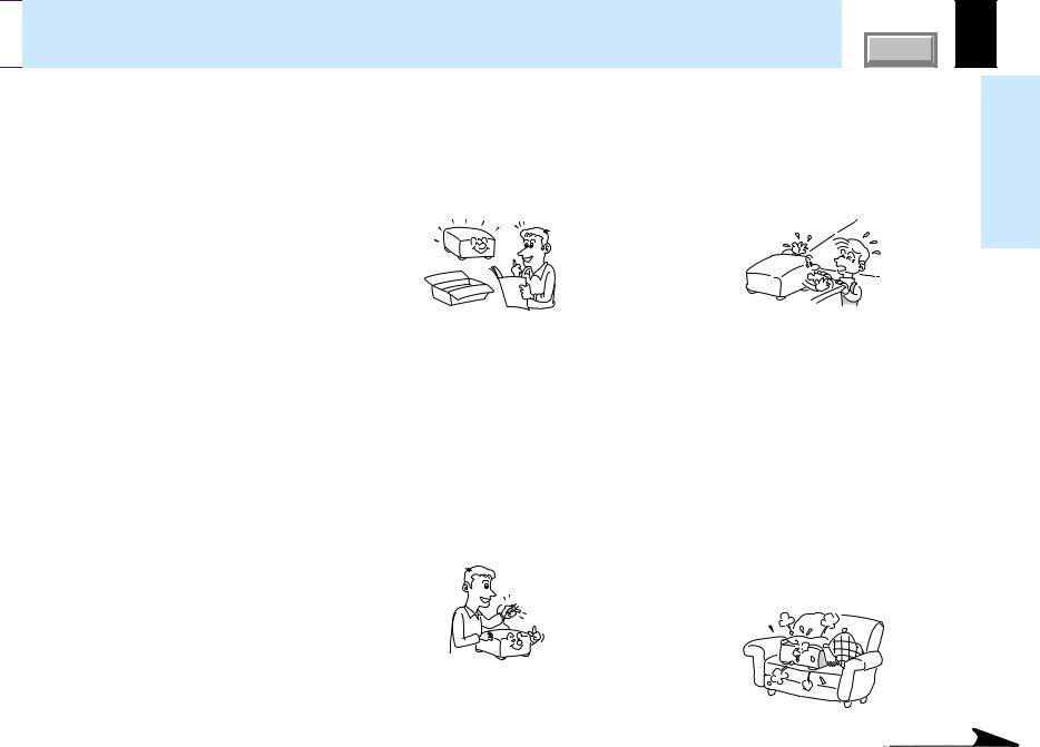
1.Read Owner’s Manual
After unpacking this product, read the owner’s manual carefully, and follow all the operating and other instructions.
2.Power Sources
This product should be operated only from the type of power source indicated on the marking label. If you are not sure of the type of power supply to your home, consult your product dealer or local power company.
For products intended to operate from battery power, or other sources, refer to the operating instructions.
3.Source of Light
Do not look into the lens while the lamp is on. The strong light from the lamp may cause damage to your eyes or sight.
4.Ventilation
Openings in the cabinet are provided for ventilation and to ensure reliable operation of the product and to protect it from overheating, and these openings must not be blocked or covered. The openings should never be blocked by placing the product on a bed, sofa, rug or other similar surface. This product should not be placed in a built-in installation such as a bookcase or rack unless proper ventilation is provided or the manufacturer’s instructions have been adhered to.
use Before
Continued

 IMPORTANT SAFETY INSTRUCTIONS (continued)
CONTENTS |
5 |
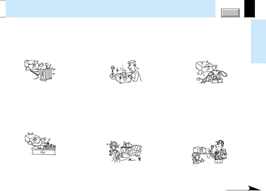
5.Heat
The product should be situated away from heat sources such as radiators, heat registers, stoves, or other products (including amplifiers) that produce heat.
7.Cleaning
Unplug this product from the wall outlet before cleaning. Do not use liquid cleaners or aerosol cleaners. Use a damp cloth for cleaning.
9.Overloading
Do not overload wall outlets; extension cords, or integral convenience receptacles as this can result in a risk of fire or electric shock.
use Before
6.Water and Moisture
Do not use this product near water – for example, near a bath tub, wash bowl, kitchen sink, or laundry tub; in a wet basement; or near a swimming pool and the like.
8.Power-Cord Protection
Power-supply cords should be routed so that they are not likely to be walked on or pinched by items placed upon or against them, paying particular attention to cords at plugs, convenience receptacles, and the point where they exit from the product.
10.Lightning
For added protection for this product during storm, or when it is left unattended and unused for long periods of time, unplug it from the wall outlet. This will prevent damage to the product due to lightning and power-line surges.
Continued

 IMPORTANT SAFETY INSTRUCTIONS (continued)
CONTENTS |
6 |
11.Object and Liquid Entry
Never push objects of any kind into this product through openings as they may touch dangerous voltage points or shortout parts that could result in a fire or electric shock. Never spill liquid of any kind on the product.
12.Do not place the product vertically
Do not use the product in the upright position to project the pictures at the ceiling, or any other vertical positions. It may fall down and dangerous.
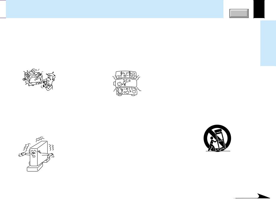
13.Stack Inhibited
Do not stack other equipment on this product or do not place this product on the other equipment.
Top and bottom plates of this product develops heat and may give some undesirable damage to other unit.
14.Attachments
Do not use attachments not recommended by the product manufacturer as they may cause hazards.
15.Accessories
Do not place this product on an unstable cart, stand, tripod, bracket, or table. The product may fall, causing serious injury to a child or adult, and serious damage to the product. Use only with a cart, stand, tripod, bracket, or table recommended by the manufacturer, or sold with the product. Any mounting of the product should follow the manufacturer’s instructions, and should use a mounting accessory recommended by the manufacturer.
A product and cart combination should be moved with care. Quick stops, excessive force, and uneven surfaces may cause the product and cart combination to overturn.
S3125A
use Before
Continued

 IMPORTANT SAFETY INSTRUCTIONS (continued)
CONTENTS |
7 |
16.Damage Requiring Service
Unplug this product from the wall outlet and refer servicing to qualified service personnel under the following conditions:
a)When the power-supply cord or plug is damaged.
b)If liquid has been spilled, or objects have fallen into the product.
c)If the product has been exposed to rain or water.
d)If the product does not operate normally by following the operating instructions. Adjust only those controls that are covered by the operating instructions as an improper adjustment of other controls may result in damage and will often require extensive work by a qualified technician to restore the product to its normal operation.
e)If the product has been dropped or damaged in any way.
f)When the product exhibits a distinct change in performance – this indicates a need for service.
17.If glass components, including lens and lamp, should break, contact your dealer for repair service.
This product incorporates glass components, including a lens and a lamp. If such parts should break, please handle with care to avoid injury and contact your dealer for repair service. The broken pieces of glass may cause to injury.
In the unlikely event of the lamp rupturing, thoroughly clean the area around the projector and discard any edible items placed in that area.
18.Servicing
Do not attempt to service this product yourself as opening or removing covers may expose you to dangerous voltage or other hazards. Refer all servicing to qualified service personnel.
19.Replacement Parts
When replacement parts are required, be sure the service technician has used replacement parts specified by the manufacturer or have the same characteristics as the original part. Unauthorized substitutions may result in fire, electric shock, or other hazards. (Replacement of the lamp only should be made by users.)
20.Safety Check
Upon completion of any service or repairs to this product, ask the service technician to perform safety checks to determine that the product is in proper operating condition.
use Before
Continued

 IMPORTANT SAFETY INSTRUCTIONS (continued)
CONTENTS |
8 |
21.Do not get your hands between the camera arm and the main unit when setting the camera arm back in its original position.
To avoid injury, be careful not to get your hands caught when setting the camera arm back in its original position. Families with children should be particularly careful.
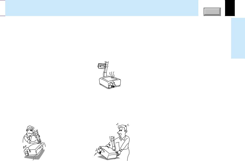
22.Do not carry by the camera arm.
Do not carry the projector by the camera arm.
Doing so can result in damage or injury.
23.Do not leave documents on the unit for long periods of time while using the document imaging function.
Do not leave texts, papers or other documents for projection on the unit for long periods of time. The heat could erase the letters on a thermal paper.
24.Do not move the projector while the arm is still erect.
Always store the arm back in position when moving the projector. Otherwise injury or damage may result.
25.Do not look into the arm light while it is lit.
The strong light may cause damage to your eyes or sight.
use Before
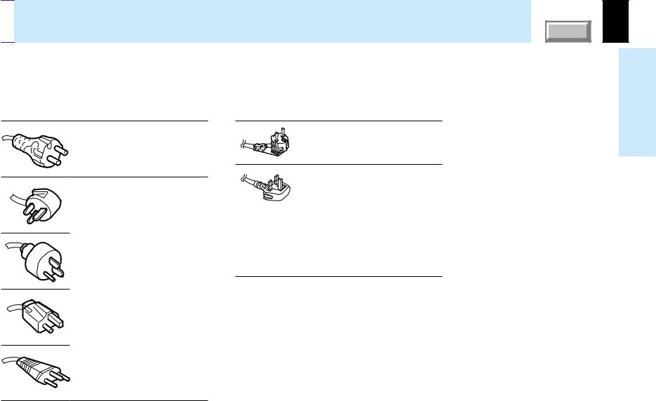

 Power supply cord selection
If your line voltage is 220 to 240V, use one of the following types of cable.
Plug |
|
Plug |
|
configuration Plug type |
Line voltage |
configuration Plug type |
Line voltage |
EURO |
220 – 240V |
EURO |
220 – 240V |
240V |
|
|
|
10 – 15A |
|
|
|
UK |
200 – 240V |
240V |
|
6A |
|
|
|
Australian |
200 – 240V |
240V |
|
10A |
|
|
|
North American |
200 – 240V |
240V |
|
15A |
|
|
|
UK |
220 – 240V |
Use a 5A fuse which is approved by ASTA or BSI to BSI362.
Always replace the fuse cover after changing the fuse.
Switzerland |
200 – 240V |
240V
6A
CONTENTS |
9
use Before

Contents |
COVER |
10 |
Before use |
|
SAFETY PRECAUTIONS ...................................................... |
2 |
IMPORTANT PRECAUTIONS ............................................... |
3 |
IMPORTANT SAFETY INSTRUCTIONS ............................... |
4 |
Power supply cord selection ............................................... |
9 |
Contents .............................................................................. |
10 |
Names of each part on the main unit................................ |
11 |
Names of each part on the remote control ...................... |
14 |
Loading batteries................................................................ |
15 |
Remote control operation .................................................. |
16 |
Adjustments & Settings |
|
Operating the menu screen ............................................... |
43 |
GUIDE MENU adjustments and settings .......................... |
45 |
FULL MENU adjustments and settings - Picture ............. |
46 |
FULL MENU adjustments - Position ................................. |
47 |
FULL MENU adjustments - Color ...................................... |
48 |
FULL MENU adjustments and settings - Audio ............... |
49 |
FULL MENU adjustments and settings - Display ............ |
50 |
FULL MENU settings - Default setting .............................. |
51 |
FULL MENU settings - Reset ............................................. |
52 |
PIP menu setting ................................................................ |
53 |
Installation and connections |
|
Floor-mounted projector placement ................................. |
17 |
Projector placement angle adjustment ............................ |
20 |
Ceiling-mounted projector placement .............................. |
21 |
Connecting a computer (COMPUTER IN 1 connector) ... |
22 |
Connecting a computer (COMPUTER IN 2 connector) .. |
23 |
Connecting video equipment ............................................ |
24 |
Projector operation control by a computer...................... |
26 |
How to use the output connector ..................................... |
27 |
Operations |
|
Projection on the screen.................................................... |
28 |
Turning the power off ......................................................... |
33 |
Adjusting the picture automatically.................................. |
34 |
Correcting the keystone distortion ................................... |
35 |
Cutting off the picture and sound temporarily ................ |
37 |
Freezing the picture ........................................................... |
38 |
Enlarging the picture size .................................................. |
39 |
Displaying PIP Sub-pictures .............................................. |
40 |
Displaying Information....................................................... |
41 |
Operating a computer by the remote control (optional) . 42 |
|
Document imaging camera |
|
Part names (of the document imaging camera model) ... |
54 |
Preparation of the document imaging camera ................ |
55 |
Picture projection with the document imaging camera .. |
56 |
Overlaying projection ......................................................... |
59 |
Locking the white balance ................................................. |
60 |
Correcting illuminated defects .......................................... |
61 |
Maintenance |
|
Trouble indications ............................................................ |
62 |
Air filter cleaning ................................................................ |
63 |
Lens and main unit cleaning ............................................. |
65 |
Lamp replacement .............................................................. |
66 |
Others |
|
Before calling service personal ........................................ |
68 |
Pin assignment of COMPUTER IN, MONITOR OUT |
|
connector ............................................................................ |
70 |
Applicable signal ................................................................ |
71 |
Controlling the projector by using RS-232C .................... |
73 |
Specifications ..................................................................... |
79 |
use Before
Names of each part on the main unit |
CONTENTS |
11 |
CAUTION |
The explanation here is only for the model without the document |
|
imaging camera. For the model with the document imaging camera, |
||
Openings in the cabinet are provided for ventilation and to |
||
refer to 54 . |
||
ensure reliable operation of the product and to protect it from |
|
|
overheating, and these openings must not be blocked or |
|
|
covered. |
|
|
|
|
Control panel 12
Infrared remote sensor 16
Anti-theft lock hole
Air exhaust |
Right side |
|
||
|
|
|
||
|
Air intake |
Rear side |
||
Front side |
|
|
||
Zooming lever |
31 |
Air intake |
||
|
||||
Lens cover |
Focusing ring |
31 |
|
|
|
|
|||
Lens
Foot adjuster 20
Foot adjuster release button 20
 Note
Note
 Left side
Speaker
Carrying handle
Open to carry the projector.
AC IN socket 19
The air exhaust discharges high temperature air. Do not put anything around the air exhaust, otherwise it may deform due to the high temperature air.
use Before
Continued


 Names of each part on the main unit (continued)
CONTENTS |
12 |
To display the menu screen and/or select operations on the menu screen. 43 44
44
Use the selection buttons and the EXIT button to enlarge the image. 39
EXIT button
Selection buttons
ENTER button
MENU button
INPUT button 30
To select the input source.
U
N
E
M
|
P |
U |
T |
IN |
|
||
|
|
||
|
|
|
|
MP |
ON |
LA |
|
|
|
R |
|
TE |
|
N |
|
|
E |
|
|
ON / STANDBY
TEMP
VOL / ADJ
ON/STANDBY button 28 33
33
To turn the projector on or off (standby).
ON indicator 28 33
33 62
62
LAMP indicator 28 33
33 62
62
TEMP indicator 62
FAN indicator 28 33
33 62
62
VOL/ADJ buttons 44
To indicate the status of the projector.
To set and/or adjust values on the menu.
To adjust the volume when the menu is not
displayed. |
32 |
|
F |
|
|
AN |
|
|
|
AUTO SET button 34 |
|
|
To adjust the computer input image |
|
EX |
automatically. |
|
|
||
IT |
KEYSTONE button 35 |
|
OS |
||
A |
|
|
U |
|
|
T |
|
|
E |
To correct the keystone distortion of |
|
T |
||
K |
||
the picture. |
||
T |
||
E |
|
|
Y |
|
|
S |
|
|
O |
|
|
N |
|
|
E |
|
use Before
 Top side
Control panel
Continued

 Names of each part on the main unit (continued)
CONTENTS |
13 |
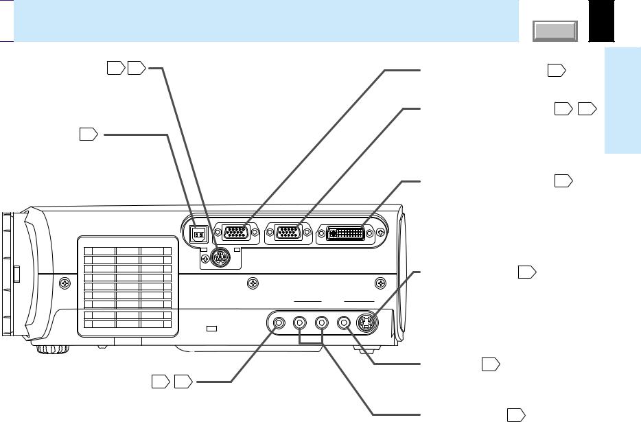
CONTROL connector 26 73
73 (RS-232C connector)
To connect a computer to control the projector. (Remove the cover to use the connector.)
USB connector 42
To connect to a USB connector of a computer when using the optional remote control mouse.
 Right side
MONITOR OUT connector 27
To connect a monitor, etc.
COMPUTER IN 1 connector 22 25
25
To enter RGB signal from a computer, etc or component video signal (Y/PB/PR Signal) from a video equipment.
COMPUTER IN 2 connector 23
To enter RGB signal from a computer, etc.
use Before
USB |
MONITOR |
COMPUTER IN 1 |
COMPUTER IN 2 |
|
OUT |
( Y/PB/PR ) |
|
CONTROL
S-VIDEO connector 24
To enter S-Video signal from video equipment, etc.
AUDIO IN jack (Audio input) 22 25
25
(ø 3.5mm stereo mini-jack)
To enter audio signal from a computer or video equipment with component video output (Y/PB/PR signal output) supported.
AUDIO |
|
VIDEO IN |
IN |
R - AUDIO - L |
VIDEO S-VIDEO |
VIDEO jack 24
To enter video signal from video equipment, etc.
AUDIO(L/R) jacks 24
To enter audio signal from video equipment, etc.

 Names of each part on the remote control
CONTENTS |
14 |
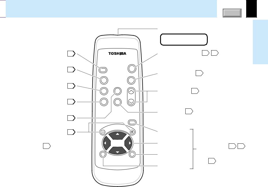
INPUT button |
30 |
To select the input source. |
|
KEYSTONE button |
35 |
To correct the keystone distortion of the picture.
FREEZE button |
38 |
To freeze the picture. |
|
PIP button |
40 |
To display the video input image as a small size picture in the computer image display window.
MUTE button |
37 |
To cut off the picture and sound temporarily.
VOL/ADJ buttons |
44 |
To set and/or adjust values on the menu. To adjust volume when the menu is not displayed. 32
|
|
ON / |
|
|
STANDBY |
INPUT |
|
|
KEYSTONE |
|
AUTO SET |
FREEZE |
MUTE |
|
PIP |
CALL |
RESIZE |
MENU
VOL / ADJ
ENTER |
EXIT |
CT-90113
Remote control transmission part
CLASS 1 LED PRODUCT
ON/STANDBY button 28 33
33
To turn the projector on or off (Standby).
AUTO SET button 34
To adjust the computer input image automatically.
RESIZE buttons 39
To enlarge the picture size.
CALL button 41
To display the information.
MENU button
Selection buttons
EXIT button
ENTER button
To display the menu screen and/or select the operation
on the menu screen. 43 44
44
Use the selection buttons and EXIT button to enlarge the image. 39
use Before
Loading batteries |
CONTENTS |
15 |
 Notes
Notes
Using batteries incorrectly can cause them to leak or burst. Strictly observe the following.
•Install the batteries with their + and – ends facing correctly.
•Do not charge, heat, disassemble, or short the batteries or throw them into a fire.
•Do not leave any exhausted batteries in the remote control.
•Do not mix different types of batteries or new and old batteries.
•When you will not be using the remote control for a prolonged period, take the batteries out of the remote control.
•When the remote control stops working or only works at very close range, replace all the batteries with new ones.
•When replacing the batteries, use longer life alkaline batteries.
•If a battery has leaked, carefully wipe off any residue inside the battery case before loading new batteries.
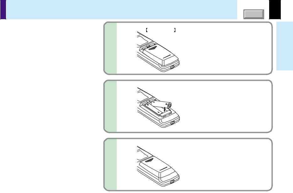
1
2
Bottom side |
Open the cover. |
|
Install the batteries.
Make sure that the +/– polarities match the illustration in the compartment.
use Before
3 |
Attach the cover. |
|

 Remote control operation
CONTENTS |
16 |
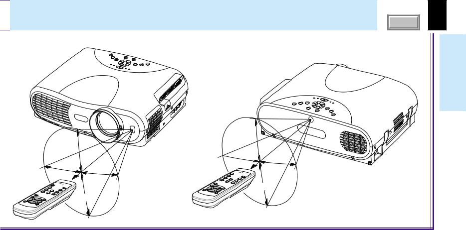
Point the remote control at the infrared remote sensor and press a button.
use Before
About 15° |
|
5m |
|
About |
|
About |
|
|
|
|
|
15° |
About 15° |
|
|
||
About 15° |
|
|
About 15°
 About 15°
 Front side
About |
5m |
|
|
About 15° |
|
 Rear side
About 15°
 Notes
Notes
•The remote control may not operate when there is sunlight or other strong light such as a fluorescent lamp shining on the projector’s remote sensor.
•Operate the remote control from a position where the remote sensor is visible.
•Do not drop the remote control or otherwise jolt it.
•Keep the remote control out of locations with excessively high temperature or humidity.
•Do not get water on the remote control or place wet objects on it.
•Do not disassemble the remote control.
•Under unusual circumstances the remote control may not operate well due to the location being used or the surroundings. At such times, change the direction of the remote control to the projector and retry the operation.

 Floor-mounted projector placement
CONTENTS |
17 |
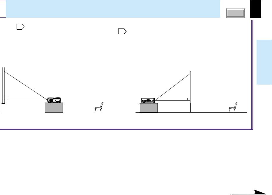
There are two ways to place the floor-mounted projector. Perform the “Projection mode” setting on the menu screen for the projection method. 51
For the ceiling-mounted projector placement, refer to the page 21 .
Floor-mounted front projection |
Floor-mounted rear projection |
||
|
Viewing a picture projected on the front of the |
Viewing a picture projected through the back of the |
|
|
screen from a floor installation. |
screen from a floor installation. |
|
|
|
|
Translucent screen |
|
|
|
|
Viewer |
Viewer |
Installationconnections and
Continued

 Floor-mounted projector placement (continued)
CONTENTS |
18 |
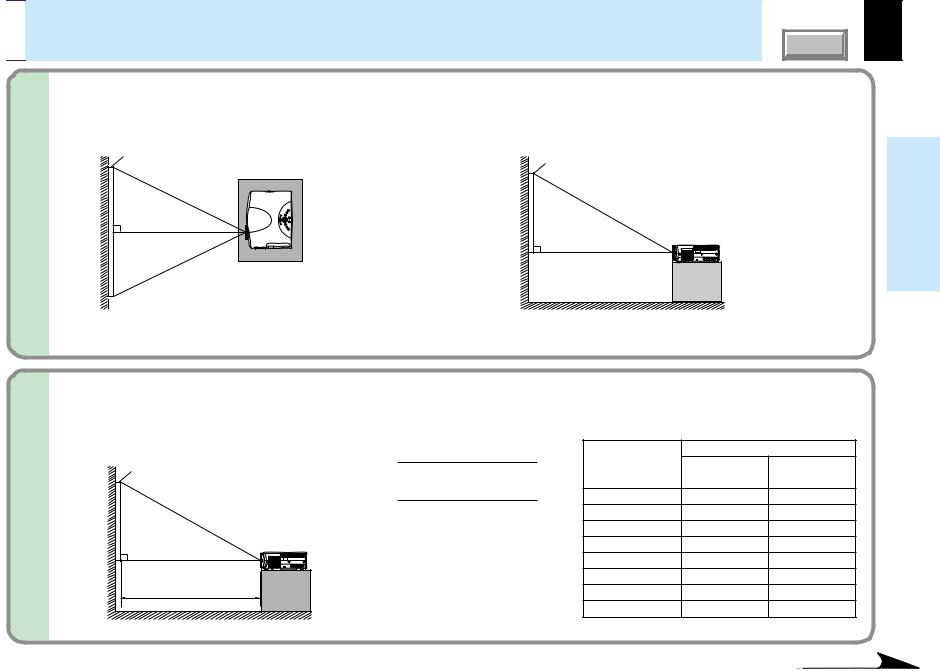
1 |
Place the projector on a steady, level surface such as a table. |
|
|
|
To obtain proper screen projection, place the projector so that the light beam hits the screen squarely. |
Top view
Screen
90°
Point the lens straight at the center of the screen as above.
Side view
Screen |
90° |
Place the projector horizontally so that the projecting light hits the screen squarely.
Installationconnections and
2 |
Determine the screen size projected on the screen. |
|
|
|
|
|
The projection size depends on the distance between the lens and the screen. |
|
|
Adjust the projection size by changing the distances as shown below. |
• The values are approximations. |
|
|
Screen |
Projection size - 1.6017 |
|
a (m) |
|
a (min.) = |
Projection size |
Minimum |
Maximum |
|
|
27.041 |
|||
|
(inches) |
(At maximum zoom) |
(At minimum zoom) |
|
|
Projection size - 1.2699 |
|||
|
32 |
– |
1.42 |
|
|
a (max.) = |
|||
|
21.463 |
40 |
1.42 |
1.80 |
|
|
|||
|
a: Distance between the lens and |
60 |
2.16 |
2.74 |
90° |
the screen (m) |
80 |
2.90 |
3.67 |
|
100 |
3.63 |
4.60 |
|
|
|
|||
|
|
150 |
5.48 |
6.93 |
|
a |
200 |
7.33 |
9.26 |
|
300 |
11.02 |
– |
|
|
|
|||
Continued
Floor-mounted projector placement (continued) |
CONTENTS |
3 |
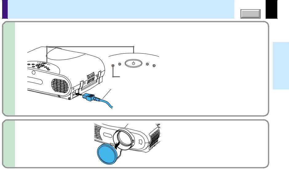
Connect the power cord. |
|
|
|
• Insert one end into the AC IN socket on the projector. |
|
• Insert the other end into a wall outlet. |
|
|
ON / STANDBY |
|
|
|
MP |
TE |
MP |
|
ON |
LA |
|
F |
|
|
|
|
AN |
Light (Orange)
Power cord (Supplied)
The three indicators, TEMP, LAMP, and ON, light in green for several seconds and then the ON indicator lights in orange and the projector turns to the standby mode.
Do not perform any operations while the three indicators are lit green.
19
Installationconnections and
4 Take off the lens cover.
 Notes
Notes
•When the projector is moved from a cold location to a warm location, or when the ambient temperature in the projection room has risen suddenly, moisture may condense on the lens or the internal optical section to blur the projected pictures. In such a case, leave the projector for an adequate time (1 to 2 hours, depending on the room’s condition) before using it, so it adjusts to the ambient temperature.
•If the screen is exposed to direct sunlight or other strong light, the projected picture will become too faint to see. Shut out the light with curtains or by other means.
•If the screen and the projector are not installed properly, the projected picture may be distorted.

 Projector placement angle adjustment
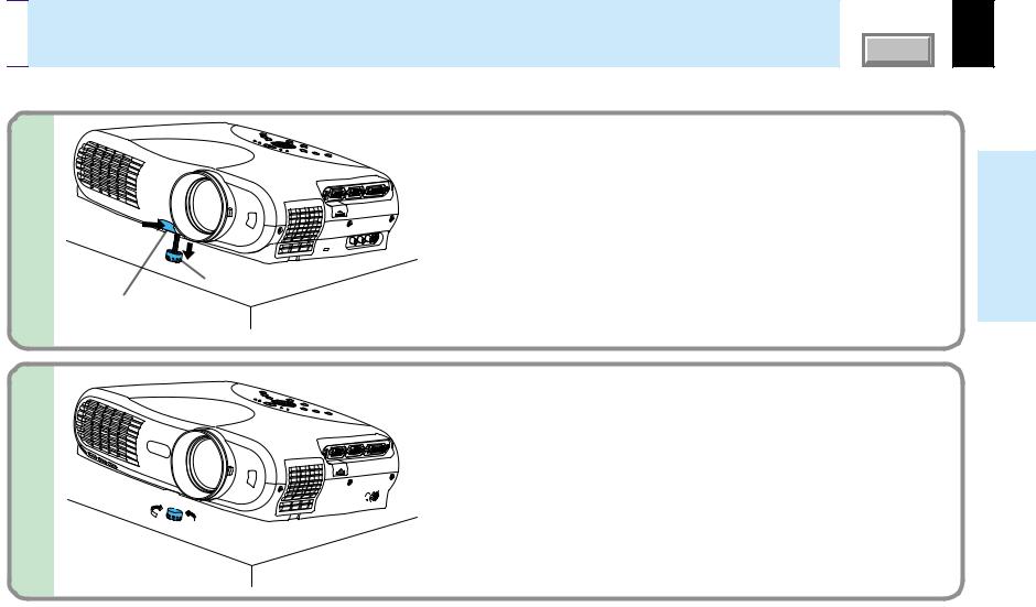
The tilt of the projector can be adjusted using the foot adjuster.
CONTENTS |
20 |
1 
Foot adjuster
Foot adjuster release button
Lift the front of the projector until the desired tilt angle is obtained and hold down the foot adjuster release button.
The foot adjuster will extend. Release the button to lock in position.
2 
Lift up 

 Lower
Lower
 Notes
Notes
Turn the foot adjuster to make fine adjustment to the height.
Turn clockwise to lift up.
Turn counterclockwise to lower.
•To put the foot adjuster back, hold down the foot adjuster release button and lower the front slowly.
•Be sure to hold the projector when putting the foot adjuster back so as not to let the front fall on your fingers.
•Do not tilt the projector at an angle exceeding the range adjustable by the foot adjusters, since the life duration of the lamp may be shortened.
Installationconnections and
Ceiling-mounted projector placement |
CONTENTS |
CAUTION
When a ceiling mount is required, please consult with the dealer.
Ceiling-mounted front projection |
Ceiling-mounted rear projection |
|||||||
Viewing a picture projected on the front of the screen from a |
|
Viewing a picture projected through the back of the screen from a |
||||||
ceiling installation. |
|
ceiling installation. |
||||||
|
|
|
|
|
|
|
|
|
|
|
|
|
|
|
|
|
|
|
|
|
|
|
|
|
|
|
Viewer |
Viewer |
Translucent screen
21
Installationconnections and
Perform the “Projection mode” setting on the menu screen for the projection method. 51
 Note
Note
The relation between the projection size and the distance to the screen is the same as that of the floor-mounted projection mode 18 .
.

Connecting a computer (COMPUTER IN 1 connector) |
CONTENTS |
You can project the picture from the computer.
Check that the power supplies for the projector and for the computer are off before connecting the cables.
USB |
MONITOR |
COMPUTER IN 1 |
COMPUTER IN 2 |
|
|
OUT |
( Y/PB/PR ) |
|
|
|
CONTROL |
|
|
|
|
|
AUDIO |
|
VIDEO IN |
|
|
IN |
R - AUDIO - L |
VIDEO S-VIDEO |
COMPUTER IN 1 connector
For use as both analog RGB (1) and Y/PB/PR input. At shipping from factory, it is set for use as analog RGB (1) input.
AUDIO IN jack
For use as both audio signals for RGB input (analog RGB (1)/analog RGB (2)/ digital RGB) and Y/PB/PR input.
Connecting a Mac adapter for
Macintosh computers (supplied)
Computer
To COMPUTER IN 1 connector Be sure to connect in the proper direction.
To monitor port
RGB cable (supplied)
To AUDIO IN jack
ø3.5mm stereo mini-jack
To audio output port
Audio cable (supplied)
22
Installationconnections and
 Notes
Notes
•The projector cannot be connected to a computer without an analog RGB connector. For details, refer to the computer manual.
•You may not be able to connect some computers to the projector. For details, consult the dealer.
•When connecting to a Macintosh computer, use the supplied Mac adapter (Multiple Scan 21 compatible). For some models the adapter is not required.
•Some computers may have output modes which are not compatible with this projector. Check the compatibility of the connectors, signal levels, timing, resolutions, etc.
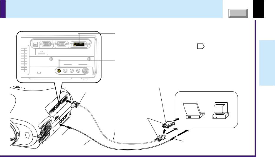
Connecting a computer (COMPUTER IN 2 connector) |
CONTENTS |
23 |
You can project the picture of analog RGB or digital RGB signal from a computer by using the COMPUTER IN 2 connector. Check that the power supplies for the projector and for the computer are off before connecting the cables.
|
|
|
|
COMPUTER IN 2 connector (DVI connector) |
|
|
|
|
For use as both analog RGB (2) input and digital RGB input. At shipping |
|
|
|
|
from factory, it set for use as Analog RGB (2) input. Change the setting on |
|
|
|
|
the menu screen when using as Digital RGB input. 45 |
USB |
MONITOR COMPUTER IN 1 |
COMPUTER IN 2 |
|
|
|
OUT ( Y/PB/PR ) |
|
|
|
|
CONTROL |
|
|
|
|
|
|
|
AUDIO IN jack |
|
IN |
R - AUDIO - L |
VIDEO S-VIDEO |
For use as both audio signals for RGB input (analog RGB (1)/analog RGB |
|
AUDIO |
VIDEO IN |
|
|
|
|
|
|
(2)/digital RGB) and Y/PB/PR input. |
|
|
|
|
Connecting a Mac adapter for |
|
|
|
|
Macintosh computers (supplied) |
|
|
|
|
Computer |
|
|
|
To COMPUTER IN 2 connector |
|
|
|
|
Be sure to connect in the proper |
|
|
|
|
direction. |
|
|
|
|
|
To monitor port |
|
|
|
|
DVI cable (supplied) |
|
To AUDIO IN jack |
ø3.5mm Stereo mini-jack |
||
|
|
|
|
|
|
|
Audio cable (supplied) |
To audio output port |
|
 Notes (Please also read “Notes” on page 22.)
•DVI digital cable needs to be purchased separately when you input a digital RGB signal.
•Although infrequent, noise might be generated on the screen depending on the types of computer and connection cables. Should this occur, reduce the refresh rate of the computer signal, or lower the resolution. Use of connection cables that are 2 m or shorter is recommended.
•The input signal specifications of the DVI port of the projector conform to DVI 1.0 specifications; however, contents protection is not supported. Note that there is no guarantee for the operations not specified in this specification.
Installationconnections and
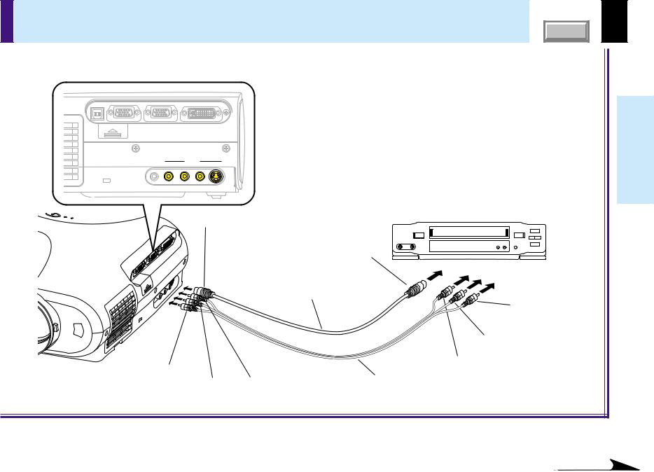
Connecting video equipment |
CONTENTS |
You can project the picture from video equipment by using VIDEO IN connectors.
Check that the power supplies for the projector and for the video equipment are off before connecting the cables.
USB |
MONITOR |
COMPUTER IN 1 |
COMPUTER IN 2 |
|
|
OUT |
( Y/PB/PR ) |
|
|
|
CONTROL |
|
|
|
|
|
AUDIO |
|
VIDEO IN |
|
|
IN |
R - AUDIO - L |
VIDEO S-VIDEO |
To S-VIDEO connector
Be sure to connect in the proper direction.
To S-video output
S-video cable (not supplied)
(Red) To AUDIO-R jack |
|
(White) To AUDIO-L jack (Yellow) To VIDEO jack |
AV cable (supplied) |
|
Video equipment
Pin plug (red)
To audio output (R)
Pin plug (white)
To audio output (L)
Pin plug (yellow)
To video output
 Note
Note
The S-VIDEO connector and VIDEO jack can be used independently, but the audio input jacks are used as both the S-VIDEO and VIDEO input.
24
Installationconnections and
Continued
Loading...