


 Loading...
Toshiba Personal Computer
TECRA M2
Maintenance Manual
TOSHIBA CORPORATION
File Number 960-468

Copyright
© 2004 by Toshiba Corporation. All rights reserved. Under the copyright laws, this manual cannot be reproduced in any form without the prior written permission of Toshiba. No patent liability is assumed with respect to the use of the information contained herein.
Toshiba Personal Computer TECRA M2 Maintenance Manual
First edition January 2004
Disclaimer
The information presented in this manual has been reviewed and validated for accuracy. The included set of instructions and descriptions are accurate for the TECRA M2 at the time of this manual's production. However, succeeding computers and manuals are subject to change without notice. Therefore, Toshiba assumes no liability for damages incurred directly or indirectly from errors, omissions, or discrepancies between any succeeding product and this manual.
Trademarks
Intel SpeedStep and Penteium are trademarks or registered trademarks of Intel Corporation or its subsidiaries in the United States and other countries/regions.
Windows and Microsoft are registered trademarks of Microsoft Corporation.
Photo CD is a trademark owned by its proprietor and used by TOSHIBA under license. Bluetooth is a trademark owned by its proprietor and used by TOSHIBA under license.
ii |
TECRA M2 Maintenance Manual (960-468) |

Preface
This maintenance manual describes how to perform hardware service maintenance for the Toshiba Personal Computer TECRA M2.
The procedures described in this manual are intended to help service technicians isolate faulty Field Replaceable Units (FRUs) and replace them in the field.
SAFETY PRECAUTIONS
Four types of messages are used in this manual to bring important information to your attention. Each of these messages will be italicized and identified as shown below.
DANGER: “Danger” indicates the existence of a hazard that could result in death or serious bodily injury, if the safety instruction is not observed.
WARNING: “Warning” indicates the existence of a hazard that could result in bodily injury, if the safety instruction is not observed.
CAUTION: “Caution” indicates the existence of a hazard that could result in property damage, if the safety instruction is not observed.
NOTE: “Note” contains general information that relates to your safe maintenance service.
Improper repair of the computer may result in safety hazards. Toshiba requires service technicians and authorized dealers or service providers to ensure the following safety precautions are adhered to strictly.
Be sure to fasten screws securely with the right screwdriver. If a screw is not fully fastened, it could come loose, creating a danger of a short circuit, which could cause overheating, smoke or fire.
If you replace the battery pack or RTC battery, be sure to use only the same model battery or an equivalent battery recommended by Toshiba. Installation of the wrong battery can cause the battery to explode.
TECRA M2 Maintenance Manual (960-468) |
iii |

The manual is divided into the following parts:
Chapter 1 Hardware Overview describes the TECRA M2 system unit and each FRU.
Chapter 2 Troubleshooting Procedures explains how to diagnose and resolve FRU problems.
Chapter 3 Test and Diagnostics describes how to perform test and diagnostic operations for maintenance service.
Chapter 4 Replacement Procedures describes the removal and replacement of the FRUs.
Appendices The appendices describe the following:
Handling the LCD module
Board layout
Pin assignments
Keyboard scan/character codes
Key layout
Wiring diagrams
BIOS rewrite procedures
EC/KBC rewrite procedures
Reliability
iv |
TECRA M2 Maintenance Manual (960-468) |

Conventions
This manual uses the following formats to describe, identify, and highlight terms and operating procedures.
Acronyms
On the first appearance and whenever necessary for clarification acronyms are enclosed in parentheses following their definition. For example:
Read Only Memory (ROM)
Keys
Keys are used in the text to describe many operations. The key top symbol as it appears on the keyboard is printed in boldface type.
Key operation
Some operations require you to simultaneously use two or more keys. We identify such operations by the key top symbols separated by a plus (+) sign. For example, Ctrl + Pause (Break) means you must hold down Ctrl and at the same time press Pause (Break). If three keys are used, hold down the first two and at the same time press the third.
User input
Text that you are instructed to type in is shown in the boldface type below:
DISKCOPY A: B:
The display
Text generated by the computer that appears on its display is presented in the type face below:
Format complete
System transferred
TECRA M2 Maintenance Manual (960-468) |
v |

Table of Contents
Chapter 1 Hardware Overview |
|
|
1.1 |
Features ...................................................................................................................... |
1-1 |
1.2 |
System Unit Block Diagram ...................................................................................... |
1-8 |
1.3 |
3.5-inch Floppy Disk Drive (USB External) ........................................................... |
1-15 |
1.4 |
2.5-inch Hard Disk Drive......................................................................................... |
1-16 |
1.5 |
DVD-ROM Drive .................................................................................................... |
1-20 |
1.6 |
CD-RW/DVD-ROM Drive...................................................................................... |
1-22 |
1.7 |
DVD±R/±RW Drive ................................................................................................ |
1-24 |
1.8 |
DVD Multi Drive..................................................................................................... |
1-25 |
1.9 |
Keyboard.................................................................................................................. |
1-27 |
1.10 |
TFT Color Display................................................................................................... |
1-28 |
1.11 |
Power Supply ........................................................................................................... |
1-30 |
1.12 |
Batteries ................................................................................................................... |
1-32 |
Chapter 2 Troubleshooting Procedures |
|
|
2.1 |
Troubleshooting ......................................................................................................... |
2-1 |
2.2 |
Troubleshooting Flowchart........................................................................................ |
2-2 |
2.3 |
Power Supply Troubleshooting.................................................................................. |
2-6 |
2.4 |
System Board Troubleshooting................................................................................ |
2-16 |
2.5 |
FDD Troubleshooting .............................................................................................. |
2-29 |
2.6 |
HDD Troubleshooting ............................................................................................. |
2-32 |
2.7 |
Keyboard and Touch pad Troubleshooting.............................................................. |
2-37 |
2.8 |
Display Troubleshooting.......................................................................................... |
2-40 |
2.9 |
Optical Drive Troubleshooting ................................................................................ |
2-42 |
2.10 |
Modem Troubleshooting.......................................................................................... |
2-44 |
2.11 |
LAN Troubleshooting.............................................................................................. |
2-46 |
2.12 |
Bluetooth Troubleshooting ...................................................................................... |
2-47 |
2.13 |
Wireless LAN Troubleshooting............................................................................... |
2-50 |
|
|
|
vi |
|
TECRA M2 Maintenance Manual (960-468) |
2.14 |
Sound Troubleshooting............................................................................................ |
2-53 |
2.15 |
SD Card Slot Troubleshooting................................................................................. |
2-56 |
Chapter 3 Tests and Diagnostics |
|
|
3.1 |
The Diagnostic Test ................................................................................................... |
3-1 |
3.2 |
Executing the Diagnostic Test ................................................................................... |
3-3 |
3.3 |
Subtest Names............................................................................................................ |
3-8 |
3.4 |
System Test.............................................................................................................. |
3-11 |
3.5 |
Memory Test............................................................................................................ |
3-14 |
3.6 |
Keyboard Test.......................................................................................................... |
3-15 |
3.7 |
Display Test ............................................................................................................. |
3-18 |
3.8 |
Floppy Disk Test...................................................................................................... |
3-22 |
3.9 |
Printer Test............................................................................................................... |
3-24 |
3.10 |
Async Test ............................................................................................................... |
3-26 |
3.11 |
Hard Disk Test ......................................................................................................... |
3-28 |
3.12 |
Real Timer Test........................................................................................................ |
3-31 |
3.13 |
NDP Test.................................................................................................................. |
3-33 |
3.14 |
Expansion Test......................................................................................................... |
3-34 |
3.15 |
CD-ROM/DVD-ROM Test ..................................................................................... |
3-35 |
3.16 |
Wireless LAN Test (Cisco)...................................................................................... |
3-36 |
3.17 |
Wireless LAN Test (Atheros) .................................................................................. |
3-41 |
3.18 |
Wireless LAN Test (Calexico)................................................................................. |
3-44 |
3.19 |
Sound/Modem/LAN Test......................................................................................... |
3-45 |
3.20 |
IEEE1394 Test ......................................................................................................... |
3-50 |
3.21 |
Bluetooth Test.......................................................................................................... |
3-51 |
3.22 |
Error Code and Error Status Names......................................................................... |
3-61 |
3.23 |
Hard Disk Test Detail Status ................................................................................... |
3-64 |
3.24 |
Head Cleaning.......................................................................................................... |
3-66 |
3.25 |
Log Utilities ............................................................................................................. |
3-67 |
3.26 |
Running Test............................................................................................................ |
3-69 |
3.27 |
Floppy Disk Drive Utilities...................................................................................... |
3-70 |
|
|
|
TECRA M2 Maintenance Manual (960-468) |
vii |
|
3.28 |
System Configuration .............................................................................................. |
3-75 |
3.29 |
SETUP ..................................................................................................................... |
3-77 |
3.30 |
Repair Initial Config Set .......................................................................................... |
3-93 |
3.31 |
Thermal Radiation Control Test .............................................................................. |
3-94 |
Chapter 4 Replacement Procedures |
|
|
4.1 |
General....................................................................................................................... |
4-1 |
4.2 |
Battery pack ............................................................................................................... |
4-8 |
4.3 |
PC card..................................................................................................................... |
4-10 |
4.4 |
SD card..................................................................................................................... |
4-11 |
4.5 |
HDD......................................................................................................................... |
4-12 |
4.6 |
Expansion memory .................................................................................................. |
4-16 |
4.7 |
Slim select bay module ............................................................................................ |
4-19 |
4.8 |
Keyboard.................................................................................................................. |
4-22 |
4.9 |
Modem Daughter Card (MDC)................................................................................ |
4-28 |
4.10 |
RTC battery.............................................................................................................. |
4-30 |
4.11 |
Cover/Touch pad...................................................................................................... |
4-32 |
4.12 |
Memory module....................................................................................................... |
4-38 |
4.13 |
Wireless LAN board ................................................................................................ |
4-40 |
4.14 |
Bluetooth module..................................................................................................... |
4-42 |
4.15 |
Display assembly ..................................................................................................... |
4-44 |
4.16 |
Sound board ............................................................................................................. |
4-49 |
4.17 |
LAN jack.................................................................................................................. |
4-52 |
4.18 |
RGB harness holder/RGB board/Modem jack ........................................................ |
4-53 |
4.19 |
Fan............................................................................................................................ |
4-57 |
4.20 |
Cooling fin/CPU ...................................................................................................... |
4-59 |
4.21 |
System board/ DC-IN jack....................................................................................... |
4-63 |
4.22 |
Speaker..................................................................................................................... |
4-64 |
4.23 |
Power switch board.................................................................................................. |
4-66 |
4.24 |
LCD unit/FL inverter ............................................................................................... |
4-68 |
4.25 |
Microphone/Wireless LAN antenna/Bluetooth antenna.......................................... |
4-79 |
4.26 |
Hinge........................................................................................................................ |
4-82 |
|
|
|
viii |
TECRA M2 Maintenance Manual (960-468) |
|

4.27 Fluorescent Lamp..................................................................................................... |
4-87 |
|
Appendices |
|
|
Appendix A |
Handling the LCD Module ........................................................................... |
A-1 |
Appendix B |
Board Layout ................................................................................................ |
B-1 |
Appendix C |
Pin Assignments............................................................................................ |
C-1 |
Appendix D |
Keyboard Scan/Character Codes .................................................................. |
D-1 |
Appendix E |
Key Layout..................................................................................................... |
E-1 |
Appendix F |
Wiring Diagrams............................................................................................ |
F-1 |
Appendix G |
BIOS Rewrite Procedures ............................................................................. |
G-1 |
Appendix H |
EC/KBC Rewrite Procedures........................................................................ |
H-1 |
Appendix I |
Reliability........................................................................................................ |
I-1 |
TECRA M2 Maintenance Manual (960-468) |
ix |

x |
TECRA M2 Maintenance Manual (960-468) |
Chapter 1
Hardware Overview

1 Hardware Overview
1-ii |
TECRA M2 Maintenance Manual (960-468) |

|
|
|
1 Hardware Overview |
|
|
|
|
Chapter 1 |
Contents |
|
|
1.1 |
Features....................................................................................................................... |
|
1-1 |
1.2 |
System Unit Block Diagram....................................................................................... |
1-8 |
|
1.3 |
3.5-inch Floppy Disk Drive (USB External)............................................................ |
1-15 |
|
1.4 |
2.5-inch Hard Disk Drive ......................................................................................... |
1-16 |
|
1.5 |
DVD-ROM Drive..................................................................................................... |
1-20 |
|
1.6 |
CD-RW/DVD-ROM Drive....................................................................................... |
1-22 |
|
1.7 |
DVD±R/±RW Drive................................................................................................. |
1-24 |
|
1.8 |
DVD Multi Drive ..................................................................................................... |
1-25 |
|
1.9 |
Keyboard .................................................................................................................. |
|
1-27 |
1.10 |
TFT Color Display ................................................................................................... |
1-28 |
|
|
1.10.1 |
LCD Module ....................................................................................... |
1-28 |
|
1.10.2 |
FL Inverter Board ............................................................................... |
1-29 |
1.11 |
Power Supply............................................................................................................ |
1-30 |
|
1.12 |
Batteries.................................................................................................................... |
|
1-32 |
|
1.12.1 |
Main Battery ....................................................................................... |
1-32 |
|
1.12.2 |
Battery Charging Control.................................................................... |
1-33 |
|
1.12.3 |
RTC battery......................................................................................... |
1-34 |
TECRA M2 Maintenance Manual (960-468) |
1-iii |

1 Hardware Overview
Figures |
|
|
Figure 1-1 |
Front of the computer ..................................................................................... |
1-6 |
Figure 1-2 |
System unit configuration............................................................................... |
1-7 |
Figure 1-3 |
System unit block diagram ............................................................................. |
1-8 |
Figure 1-4 |
3.5-inch FDD (USB External)...................................................................... |
1-15 |
Figure 1-5 |
2.5-inch HDD ............................................................................................... |
1-16 |
Figure 1-6 |
DVD-ROM drive.......................................................................................... |
1-20 |
Figure 1-7 |
CD-RW/DVD-ROM drive ........................................................................... |
1-22 |
Figure 1-8 |
DVD±R/±RW Drive..................................................................................... |
1-24 |
Figure 1-9 |
DVD Multi drive .......................................................................................... |
1-25 |
Figure 1-10 |
Keyboard ...................................................................................................... |
1-27 |
Figure 1-11 |
LCD module ................................................................................................. |
1-28 |
Tables |
|
|
Table 1-1 |
3.5-inch FDD specifications......................................................................... |
1-15 |
Table 1-2 |
2.5-inch HDD specifications ........................................................................ |
1-16 |
Table 1-3 |
DVD-ROM drive specifications................................................................... |
1-20 |
Table 1-4 |
CD-RW/DVD-ROM drive specifications .................................................... |
1-22 |
Table 1-5 |
DVD±R/±RW drive specifications............................................................... |
1-24 |
Table 1-6 |
DVD multi drive specifications.................................................................... |
1-25 |
Table 1-7 |
LCD module specifications .......................................................................... |
1-28 |
Table 1-8 |
FL inverter board specifications................................................................... |
1-29 |
Table 1-9 |
Power supply output rating........................................................................... |
1-31 |
Table 1-10 |
Battery specifications ................................................................................... |
1-32 |
Table 1-11 |
Time required for quick charges................................................................... |
1-33 |
Table 1-12 |
RTC battery charging/data preservation time............................................... |
1-34 |
1-iv |
TECRA M2 Maintenance Manual (960-468) |

1.1 Features |
1 Hardware Overview |
1.1Features
The Toshiba TECRA M2 Personal Computer uses extensive Large Scale Integration (LSI), and Complementary Metal-Oxide Semiconductor (CMOS) technology extensively to provide compact size, minimum weight, low power usage and high reliability. This computer incorporates the following features and benefits: The product configuration is BTO/CTOcompatible so that a system can be designed to suit a specific purpose.
Microprocessor (BTO)
The TECRA M2 computer is equipped with an Intel Banias Processor. The Intel Banias Processor incorporates a math co-processor, a 64KB L1 cache memory and a 1MB L2 cache memory.
The processor runs with one of the following speeds:
Intel Banias Processor
• Intel Banias Processor 1.4GHz / 1.5GHz / 1.6GHz / 1.7GHz (1.484V) These processors operate at 400MHz bus clock.
Chipset
The TECRA M2 is equipped with Intel Odem, Intel ICH4-M and YEBISU3S.
Video Controller
The computer has a nVIDIA NV34M VGA controller. The internal VRAM is 32MB (64MB is also supported.), DDR250MHz.
Memory (BTO)
Two memory slots are provided to accommodate 2.5V drive PC2100/PC2700 DDRSDRAM memory units with a total capacity of 2GB (2,048MB) maximum.
The following four memory modules are available.
• |
128 MB |
(16M×16bit×4, 2.5V, SDRAM) |
• |
256 MB |
(16M×16bit×8, 2.5V, SDRAM) |
• |
512 MB |
(32M×8bit×16, 2.5V, SDRAM) |
•1,024MB (64M×8bit×16, 2.5V, SDRAM)
HDD (BTO)
The computer has a 2.5-inch HDD. The following capacities are available.
•30/40/60/80GB
TECRA M2 Maintenance Manual (960-468) |
1-1 |

1 Hardware Overview |
1.1 Features |
USB FDD (BTO)
A 3.5-inch USB FDD accommodates 2HD (1.44MB) or 2DD (720KB) disks.
Slim Select Bay (BTO)
A DVD-ROM drive, CD-RW/DVD-ROM drive, DVD±R/±RW drive, DVD Multi drive, 2nd HDD or 2nd Battery can be installed in the Slim Select Bay.
DVD-ROM Drive (BTO)
A full-size and runs either 12cm (4.72-inch) or 8cm (3.15-inch) DVD/CDs without an adaptor. It plays DVDs at maximum 8-speed and reads CDs at maximum 24-speed.
CD-RW/DVD Drive (BTO)
A full-size, CD-RW/DVD drive that contains an AT Attachment Packet Interface (ATAPI) controller. This drive reads CD-R at maximum 24-speed and reads DVD-ROM at maximum 8-speed.
DVD±R/±RW Drive (BTO)
This full size DVD±RW/±RW drive module lets you record data to rewritable CD/DVDs as well as run either 12 cm (4.72-inch) or 8 cm (3.15-inch) CD/DVD without using an adaptor. It is a high-performance drive that reads DVD at maximum 8-speed, writes DVD-R/-RW at 2-speed, DVD+R/+RW at 2.4-speed and reads CD at maximum 24-speed (3,600 KB per second).
DVD Multi Drive (BTO)
This drive is a combination of DVD-ROM and CD-R/RW Drive. It is full-size and runs either 12cm (4.72-inch) or 8cm (3.15-inch) DVD/CDs without an adaptor. It plays DVDs at maximum 8-speed, writes CD-R at maximum 8-speed, writes CD-RW at maximum 4- speed, and reads CDs at maximum 24-speed.
Display (BTO)
The display comes in the following two types:
•14.1” XGA-TFT color display, resolution 1,024×768, 16M colors
•14.1” SXGA+-TFT color display, resolution 1,400×1,050, 16M colors
A video controller and a 32/64MB VRAM enables an external monitor to display 16M colors at a resolution of 1,024×768 pixels or 1,400×1,050 pixels.
1-2 |
TECRA M2 Maintenance Manual (960-468) |

1.1 Features |
1 Hardware Overview |
Keyboard
An-easy-to-use 85(US)/86(UK)-key keyboard provides a numeric keypad overlay for fast numeric data entry or for cursor and page control. The keyboard also includes two keys that have special functions in Microsoft Windows 2000/XP. It supports software that uses a 101or 102-key enhanced keyboard.
TOSHIBA Dual Pointing Device
The TOSHIBA Dual Pointing Device consists of Touch Pad and AccuPoint. The touch pad and control buttons enable control of the on-screen pointer and scrolling of windows. The pointer control stick, AccuPoint enables convenient control of the cursor.
Batteries
The computer has two or three batteries: a rechargeable Lithium-Ion main battery pack and RTC battery (that backs up the Real Time Clock and CMOS memory).
Second battery can be mounted in the slim select bay as an option.
Universal Serial Bus (USB2.0)
Two USB ports are provided. The ports comply with the USB2.0 standard, which enables data transfer speeds 40 times faster than USB1.1 standard. USB1.1 is also supported.
IEEE 1394 port (BTO)
The computer comes with one IEEE 1394 port. It enables high-speed data transfer directly from external devices such as digital video cameras.
Parallel port
The parallel port enables connection of parallel printer or other parallel devices. (ECP compatible)
External monitor (RGB) port
The port enables connection of an external monitor, which is recognized automatically by Video Electronics Standards Association (VESA) Display Data Channel (DDC) 2B compatible functions.
PC card slot
The PC card slot (PCMCIA) accommodates two Type II cards or one Type III card. The slot supports 16-bit PC cards and Card Bus PC cards. CardBus supports 32-bit PC cards.
TECRA M2 Maintenance Manual (960-468) |
1-3 |

1 Hardware Overview |
1.1 Features |
SD Card
The SD Card Slot can accommodate Secure Digital flash memory cards with various capacities. SD cards let you easily transfer data from devices, such as digital cameras and Personal Digital Assistants, which use SD Card flash-memory.
Docking interface port
The docking interface port enables connection of an optional Advanced Port Replicator III. It provides additional features as follows:
•RJ-45 LAN jack, RJ-11 Modem jack
•External monitor port
•PS/2 mouse and PS/2 keyboard ports
•Parallel port
•Serial port
•DC IN socket
•Audio line-in, line out jack
•Four USB ports
•IEEE 1394 port
•DVI port
Infrared port
The infrared port is compatible with Fast InfraRed (FIR) standards enabling cableless 4 Mbps, 1.152 Mbps, 115.2 kbps, 57.6 kbps, 38.4 kbps, 19.2 kbps or 9.6 kbps data transfer with Infrared Data Association (IrDA) 1.1 compatible external devices.
Sound system
The sound system is equipped with the following features:
•AC Link (in ICH4-M) and Analog Deveices AD1981B
•AMP: Matsushita AN12490 and NSC LM4911
•Stereo speakers
•Built-in microphone
•Volume control knob
•Stereo headphone jack
•External microphone jack
•Supports VoIP
1-4 |
TECRA M2 Maintenance Manual (960-468) |

1.1 Features |
1 Hardware Overview |
Video-out jack
The video jack enables to transfer NTSC or PAL data to external devices connected with S-Video cable.
Internal modem
The internal modem is equipped as a modem daughter card (MDC).
The internal modem provides capability for data and fax communication and supports V.90/92. For data reception it operates at 56,000bps and for data transmission it operates at 33,600bps. For fax transmission it operates at 14,400bps. It is also equipped with Speakerphone and TAM (Telephony Answering Machine) function. The speed of data transfer and fax depends on analog telephone line conditions. It has a RJ11 modem jack for connecting to a telephone line. Both of V.90 and V.92 are supported in USA and Canada. In other regions, only V.90 is available.
Internal LAN
The computer is equipped with LAN circuits that support Ethernet LAN (10 megabits per second, 10BASE-T), Fast Ethernet LAN (100 megabits per second, 100 BASE-TX) and Gigabit Ethernet LAN (1000 megabits per second, 1000BASE-T). It also supports Wakeup on LAN (WOL), Magic Packet and LED.
Bluetooth (BTO)
The computer is equipped with Bluetooth (V1.1) communications standard enable wireless connection between electronic devices such as computers and printers. It supports kill SW.
Mini PCI card slot (BTO)
The computer is equipped with Wireless LAN board compatible with the Standard of IEEE 802.11b, IEEE 802.11a/b, IEEE 802.11b/g, or IEEE 802.11a/b/g in the Mini PCI card slot.
Presentation button
This button switches the display between internal display, external display, simultaneous display and multi-monitor display.
Toshiba Console button
When this button is pressed during power-on, the PC is connected to “Toshiba Console”. When this button is pressed during power-off, the PC is turned on and connected to “Toshiba Console”.
TECRA M2 Maintenance Manual (960-468) |
1-5 |
1 Hardware Overview |
1.1 Features |
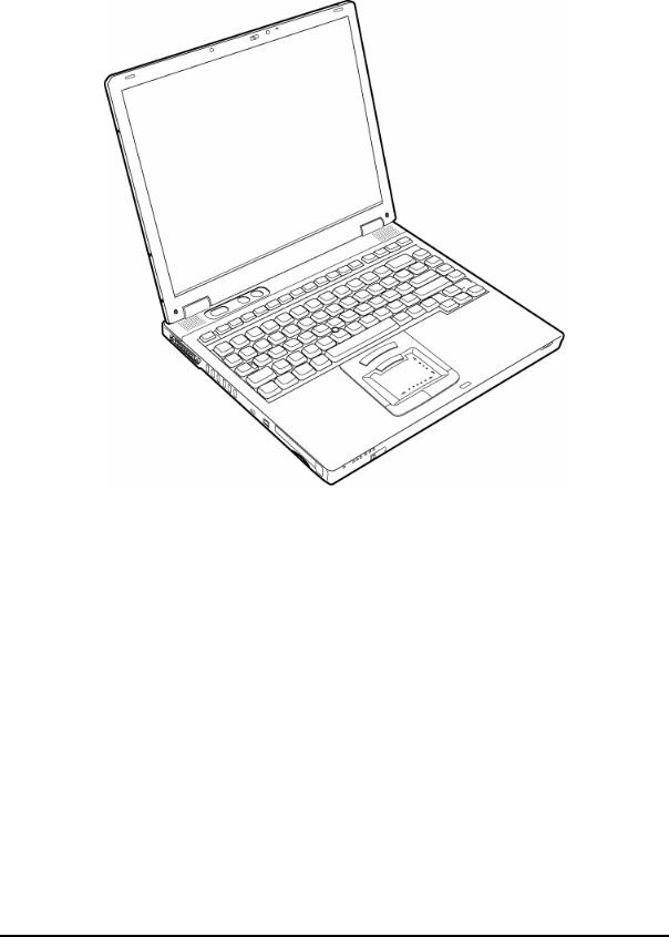
The front of the computer is shown in figure 1-1. |
|
Figure 1-1 Front of the computer
1-6 |
TECRA M2 Maintenance Manual (960-468) |
1.1 Features |
1 Hardware Overview |
The system unit configuration is shown in figure 1-2. |
|
Figure 1-2 System unit configuration
TECRA M2 Maintenance Manual (960-468) |
1-7 |

1 Hardware Overview |
1.2 System Unit Block Diagram |
1.2System Unit Block Diagram
Figure 1-3 is a block diagram of the system unit.
Figure 1-3 System unit block diagram
1-8 |
TECRA M2 Maintenance Manual (960-468) |

1.2 System Unit Block Diagram |
1 Hardware Overview |
The system unit is composed of the following major components:
Processor
•Intel Banias Processor 1.40GHz/1.50GHz/1.60GHz/1.70GHz
–Processor core speed:1.40GHz/1.50GHz/1.60GHz/1.70GHz
–Processor bus speed: 400MHz
–Integrated L1 cache memory: 32KB instruction cache and 32KB write-back data cache, 4-way set associative
–Integrated L2 cache memory: 1MB ECC protected cache data array, 8-way set associative
–Integrated NDP
Memory
Two BTO-compatible memory slots are provided. Expansion up to 2GB (2,048MB) is available.
•DDR-SDRAM (Double Data Rate - Synchronous DRAM)
•128MB/256MB/512MB/1GB selectable
– |
128 MB |
(16M×16bit×4) |
– |
256 MB |
(16M×16bit×8) |
– |
512 MB |
(32M×8bit×16) |
– |
1GB |
(64M×8bit×16) |
•200 pin, SO Dual In-line Memory Modules (SO-DIMM)
•2.5 volt operation
•Supports DDR266 (128MB, 256MB, 512MB and 1GB) and DDR333 (256MB, 512MB and 1GB)
•Supports PC2100 and PC2700
Intel Odem (North Bridge)
•One Intel RG82855MP is used.
•Features:
–Banias Processor System Bus Support
–DRAM Controller: DDR333/DDR266 Support, 2GB max
–Accelerated Graphics Port Interface: adheres to AGP2.0, AGP×4 mode
–Hub Link Interface
–593-ball 37.5×37.5 mm FC-BGA package
TECRA M2 Maintenance Manual (960-468) |
1-9 |

1 Hardware Overview |
1.2 System Unit Block Diagram |
Intel ICH4-M (South Bridge)
•One Intel FW82801DBM is used.
•This gate array has the following features:
–Hub Link Interface
–PCI Rev2.2 Interface (6 PCI REQ/GNT Pairs)
–BusMaster IDE Controller (Ultra ATA 100/66/33)
–USB 1.1/2.0 Controller 6 Ports (EHCI: Enhanced Host Controller)
–I/O APIC (ACPI 1.0b)
–SMBus2.0 Controller
–FWH Interface (BIOS)
–LPC Interface (EC/KBC, Super I/O)
–IRQ Controller
–Serial Interrupt Controller
–Power Management Controller
–Deeper Sleep (C4) Support
–Suspend/Resume Control
–AC'97 2.2 Interface
–Internal RTC
–Internal LAN Controller (WfM2.0)
–421-ball 31×31mm BGA Package
PC Card Controller Gate Array
•One YEBISU3S gate array is used.
•This gate array has the following functions and components.
–PCI interface (PCI Rev. 2.2)
–CardBus/PC Card controller (Yenta2 Ver. 2.2)
–SD memory card controller (SDHC Ver. 1.2)
–SD IO card controller (Ver. 1.0)
–SmartMedia controller (SMHC Ver.01/SMIL1.0) (not used in this computer)
–SIO (UART) controller (MS Debug Port Specification Ver. 1.0)
–Docking station interface (Q-SW control, reset control)
–External device interface
1-10 |
TECRA M2 Maintenance Manual (960-468) |

1.2 System Unit Block Diagram |
1 Hardware Overview |
Firmware Hub (FWH)
•One STMicro M50FW080N1 is used.
•This gate array has the following features:
–Firmware hub hardware interface mode
–Two configurable interfaces
–Program/erase controller
–Program and erase suspend
–8Mbits of flash memory for platform code/data nonvolatile storage
–Address/Address-Multiplexed (A/A Mux) interface/mode
–Case temperature operating range
–Vcc: 3V to 0.36V
–Vpp: 12V for fast programming
•8Mbits of flash memory are used as shown below:
–64KB are used for VGA-BIOS.
–288KB are used for system BIOS.
–8KB are used for plug and play data area.
–8KB are used for password security.
–16KB are used for boot strap.
–32KB are used for ACPI P code.
–48KB are used for LOGO.
–128KB are reserved for LAN BIOS.
−432KB are reserved.
VGA Controller
One nVIDIA NV34M chip is used. The video controller incorporates graphics accelerator and video accelerator.
•Internal VRAM, 32MB/64MB DDR 250MHz
•AGP bus R2.0 ×4
•LCD Interface LVDS 2ch
•TV Encoder: Supports S-video
•DVI Supported by Dock
Sound Controller
•One AC'97Codec AD1981B chip and AC-Link controller embedded in ICH4-M
•SW sound
TECRA M2 Maintenance Manual (960-468) |
1-11 |

1 Hardware Overview |
1.2 System Unit Block Diagram |
EC/KBC (Embedded Controller/Keyboard Controller)
•One Mitsubishi M306K9FCLRP micon chip functions as both EC and KBC.
•EC
This controller controls the following functions:
–Power supply sequence
–Thermal conditions
–LEDs
–Beep
–Device ON/OFF
–Fan speed
–Universal I/O port
–Docker Docking Sequence
–Battery capacity check
–Forced reset
–Flash rewriting
–EC interface
–I2C communication
–EC access
–Slim Select Bay Control
•KBC
This controller has the following functions:
–Scan controller to check status of keyboard matrix
–Interface controller between the keyboard scan controller and the system
–Control of switching and simultaneous operation of the accupoint and internal keyboard
PSC (Power Supply Controller)
•One TMP87PM48U chip is used.
•This controller controls the power sources.
Clock Generator
•One ICS950812CGT is used.
•This device generates the system clock.
1-12 |
TECRA M2 Maintenance Manual (960-468) |

1.2 System Unit Block Diagram |
1 Hardware Overview |
Modem Controller
•One built-in modem card with Agere SCORPIO+CSP1037B is used.
•This controller has the following functions:
–One RJ11 port
–Digital line protection support
–Ring wake up support
–Analog audio support
–AC97 interface
–The following communication codes are supported
Data:
V.90 (56K bps) data communication control
V.92 (56K bps) data communication control
V.34 (33.6K to 2400bps) data communication control
V.44, V.42, V.42bis and MNP class 5 data compression
V.32 turbo, V.32 bis and fallbacks
Fax:
V.34 (33.6K to 2400 bps)
V.17 (14.4K, 12K, 7200 bps)
V.29 (9600, 7200 bps)
V.27 ter (4800, 2400 bps)
V.21 ch2 (300 bps)
Internal LAN Controller
•One MAC incorporated with ICH4-M and PHY (Kinnereth-R 82562EZ) or 82540EP (KENAI32M) are used for the internal chip, and are connected with RJ11/RJ45 combo connector.
•This controller has the following functions:
–Gigabit-Ethernet ([MAC+PHY] 82540EP)
–10/100M-Ethernet ([MAC] ICH4M+[PHY]82562EZ)
–WOL support
–Magic Packet support
–LED support
Wireless LAN
•One Mini PCI card for wireless LAN with Type IIIA card bus controller. Ardon (Intel) or AR5121 (Askey) Mini PCI I/F controller is used.
Super I/O
•One SMSC Kona-Lite chip is used.
•This gate array has the following features:
–Floppy Disk Controller
–Infrared Communications Controller
–Parallel Port Controller
TECRA M2 Maintenance Manual (960-468) |
1-13 |

1 Hardware Overview |
1.2 System Unit Block Diagram |
IEEE1394
•One Ti TSB43AB22 is used.
Sensor
•Thermal Sensor: One ADM1032AR chip is used.
•LCD Sensor: One NRS-701-1015T chip is used.
1-14 |
TECRA M2 Maintenance Manual (960-468) |
1.3 3.5-inch Floppy Disk Drive |
1 Hardware Overview |
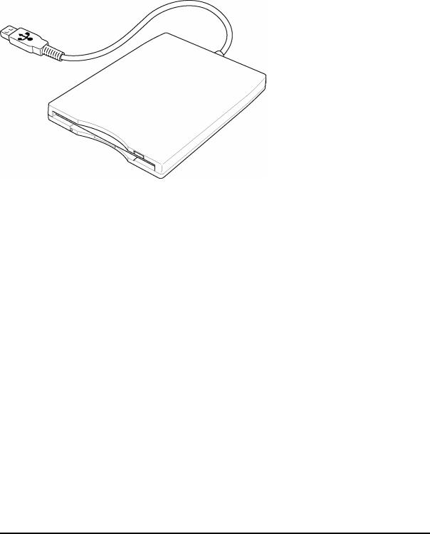
1.33.5-inch Floppy Disk Drive (USB External)
The 3.5-inch FDD is a thin, high-performance reliable drive that supports 720KB (formatted) 2DD and 1.44MB (formatted) 2HD disks.
The FDD is shown in figure 1-4. The specifications for the FDD are listed in Table 1-1.
|
|
|
|
|
|
|
|
|
|
Figure 1-4 3.5-inch FDD (USB External) |
|
|
|||
|
|
Table 1-1 |
3.5-inch FDD specifications |
|
|
||
|
|
|
|
|
|
|
|
|
Items |
|
720KB mode |
|
1.44MB mode |
||
Data transfer rate |
FDD part |
|
250K bits/second |
|
500K bits/second |
||
|
|
|
|
|
|
||
|
|
USB |
|
Full speed mode (12M bits/second) |
|||
|
|
|
|
|
|
||
Disk rotation speed |
|
300rpm |
|
|
|||
|
|
|
|||||
Track density |
|
5.3 track/mm (135TPI) |
|||||
|
|
|
|
|
|
|
|
TECRA M2 Maintenance Manual (960-468) |
1-15 |
1 Hardware Overview |
1.4 2.5-inch Hard Disk Drive |
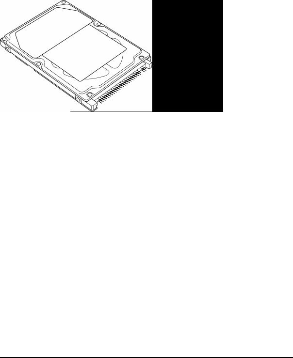
1.42.5-inch Hard Disk Drive
The removable HDD is a random access non-volatile storage device. It has a non-removable 2.5-inch magnetic disk and mini-Winchester type magnetic heads.
The computer supports a 30GB, 40GB, 60GB and 80GB HDD.
The HDD is shown in figure 1-5. Specifications are listed in Table 1-2.
Figure 1-5 2.5-inch HDD
Table 1-2 2.5-inch HDD specifications (1/4)
|
|
|
|
|
Specifications |
|
|
Items |
|
|
|
|
|
|
TOSHIBA |
|
ITACHI GST |
HITACHI GST |
||
|
|
|
|
|||
|
|
|
HDD 2181B |
|
G8BC0000Z310 |
G8BC00017310 |
|
|
|
|
|
|
|
Outline |
|
Width (mm) |
69.85 |
|
69.85 |
69.85 |
dimensions |
|
Height (mm) |
9.5 |
|
9.5 |
9.5 |
|
|
|
|
|
|
|
|
|
Depth (mm) |
100 |
|
100.2 |
100 |
|
|
Weight (g) |
99 max. |
|
95 max. |
91 |
Storage size (formatted) |
30GB |
|
30GB |
30GB |
||
|
|
|
|
|
||
Speed (RPM) |
4,200 |
|
4,200 |
4,200 |
||
|
|
|
|
|
||
Data transfer speed (Mbits/s) |
154.3 – 298.0 |
|
- |
183.2-347.2 |
||
|
|
|
|
|
||
Interface transfer rate (MB/s) |
|
100 max.(Ultra DMA mode) |
||||
|
|
|
|
|||
Track density (Ktpi) |
78.9 |
|
63 |
80 |
||
|
|
|
|
|
||
Average seek time (ms) |
|
|
|
|
||
Read |
|
|
12 |
|
12 typ. |
13 typ. |
Write |
|
|
|
|
14 typ. |
- |
|
|
|
|
|
||
Motor startup time (ms) |
4 typ |
|
5 |
5 typ. (Power on) |
||
|
|
|
|
|
|
|
1-16 |
TECRA M2 Maintenance Manual (960-468) |
Loading...