


T2E
Table of contents
 Loading...
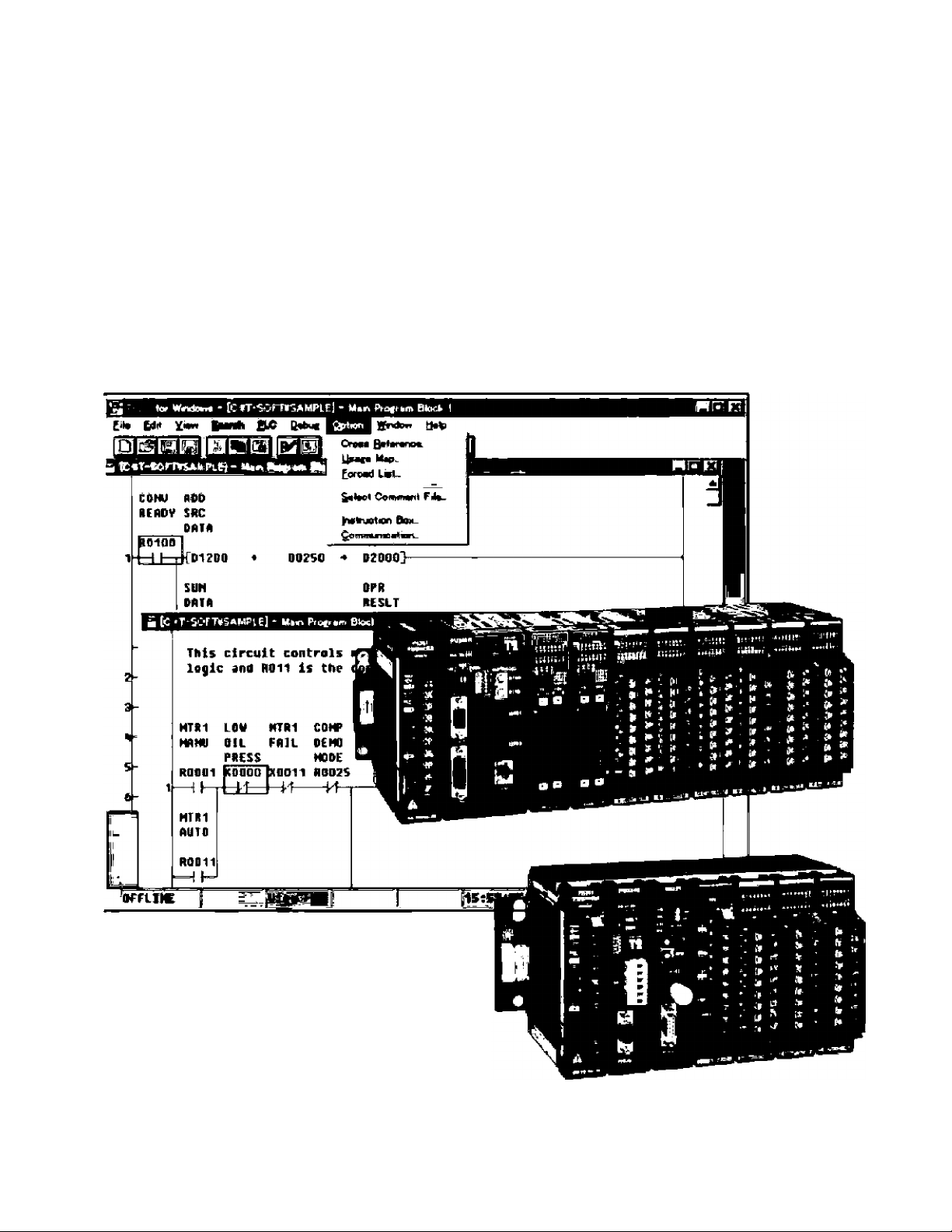
TOSHIBA
PROGRAMMABLE CONTROLLER
PROSEC T2E/T2N
Advanced Features
• Floating-Point Math
• Large Program & Data Memory
• Ethernet/DeviceNet Networks
• Active Serial ASCII Port
• Two Programming Languages
• MS Windows Programming Software
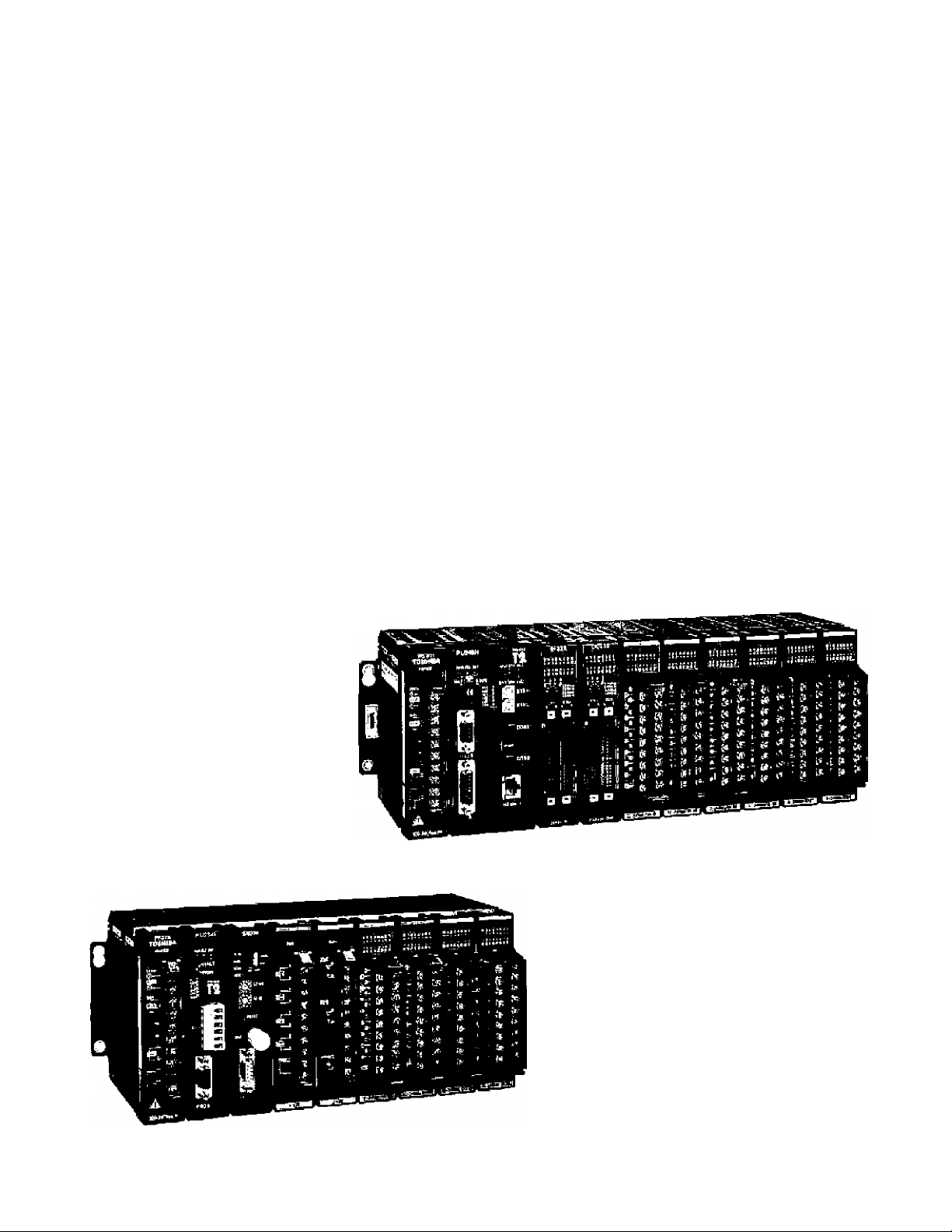
PROSEC T2E/T2N
Small, Powerful Modular Style
Programmable Controllers
Toshiba’s T2E/T2N are small, modular type programmable
controller suitable for both relay replacement and
complex control applications. The T2E/T2N are
2nd generation T2 CPUs. The T2ETT2N
provide afunctional, economical, and
compact solution to a wide range
of OEM and user applications
in automotive, machine
control, and process
control systems.
T2N
Local I/O: Max. 2048 points
Program: 23.5 k steps
0.33 ps/contact
1.2 ps/transfer
Speed:
Local I/O: Max. 1024 points
Program: 9,5 k steps
Speed: 0.33 ps/contact
1.2 ps/trarsfer

Key Features
High speed processing
The Т2ЕЯ2Ы excels at applicartions where high speed
processing is required.
• 0.33 ps/contact • 0.44 ps/coii
• 1.2 ps/16*bit transfer • 1.63 ps/16*bit addition
Advanced instruction set
The T2E/T2N offers 24 basic relay-ladder instructions
and 192 function block instructions, including the
following.
• Arithmetic operation • Data manipulations
• Trigonometric functions • PID/ramp/intsgral
• Subroutine call • For-Next loop
• Averaging/filteiing • ASCII ** Hex conversion
• Floating-point math
Two programming Languages
The T2E/T2N supports two programming languages:
Ladder Diagram {LD) and Sequential Function Chart
(SFC). By selecting the appropriate language, or
coinbination of the two, program developrrtent time
can be greatly reduced.
Built-in clock/calendar
TheT2E/T2N has a real-time-clock/catendar function
(year, month, day, week, hours, minutes, seconds)
that can be used for performing scheduled
operations, data gathering with time stamps, etc,
Password protection
The T2E/T2N can be programmed with one of four
selectable protection levels.
• Level 1: No protect (normal)
• Level 2: Wrlting/moditying program prohibited
• Level 3: Level 2 plus viewing program prohibited
• Level 4: Level 3 plus writing data prohibited
Battery-fess operation fT2E)
The user-program is saved in a built-in Flash
memory. No battery maintenance is required.
Ethernet connection (T2N|
The T2N CPU modules (PU235N and PU245N) have
built-in Ethernet interface (10BASE-T). Through the
Ethernet, the T2N can communicate with higher level
controllers (computer, workstation, etc.) or other
PLCs with Ethernet.
High speed industrial LAN
The T2E/T2N can be connected to Toshiba’s high
speed industrial LANs (Local Area Networks)
TOSLINE-S20 and TOSLINE-FIO. Tbe TOSLINE
series are suited for real-time control data linkage.
Through these networks, the T2E/T2N can exchange
data with other Toshiba equipment, such as the
TOSDiC CIE system, other T-sehes PLCs, Large
Adjustable Speed Drives, General Purpose Inverters,
etc.
The T2N CPU module PU245N has the TOSUNE-
S20LP (Loop version) built-in into the CPU module.
The TOSLINE-S20LP is a high-ral¡ability double-loop
fiber optic S20 rtetwork.
Device Net
A DeviceNat scanner module Is avalable for the
T2E/T2M. The DeviceNet scanner module can
read/write data to any other manufacturer's ODVA
certified devices (I/O blocks. Inverters to include
Toshiba’s G3, air valve manifolds, sensors, etc.).
Flexible serial port
The T2En-2N has RS-232C or RS-485 serial
communication port, (It is optional in the T2E)
Using this port, one of the following communication
modes can be selected.
• Computer link mode: Connection with higher level
computer, MMl/SCADA system, modem, etc.
• Data link mode: Easy data linkage between two
T2Es, T2Ns, T2E—T2N or T2E/T2N—Super T1.
• Free ASCII mode: Active communication between
serial ASCII devices, (bar code readers, etc.)
Programmer port function
The T2E/T2N*s RS-232G programmer port supports
the T-series computer link protocol. This allows easy
connection to a higher level computer, an operator
interface unit, a modem, etc.
System Configuration
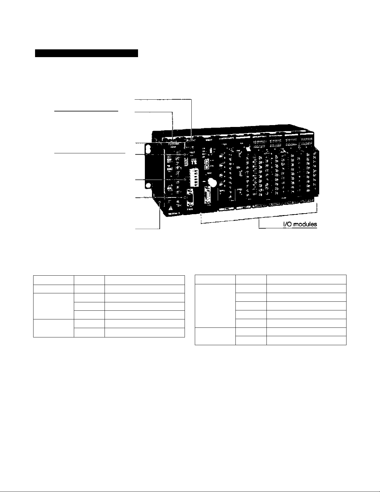
T2E CPU Unit Configuration
CPU module
Power supply module
CPU status indicators
Operation nKJde switch
Optional communicatliMi port
(Add-on option card,
RS-2^C or RS-4S5)
_______
Programmer port (RS-232C)
Rack
T2E basic components
item Type
Description
CPU module
PU234E
9.5 k steps, clock/calendar
CPU add-on
option card
CM231E
RS-48S port, w/ battery
CM232E RS-232C port, w/ battery
BT231E
Battery card
Power supply
module
PS261 100 to 240 Vac
PS31 24 Vdc
Item
Type Description
CPU rack BU218
8 irO slots, expandable
UBB2
7 I/O slots, expandaUe
UBBl
4 I/O slots, expandable
UBA2
7 I/O ^ots, non expandable
UBAI 4 I/O slots, non ej^ndable
Expansion
rack
BU2E8 8 I/O slots
BU2&6
6 I/O slots
• The CM231E and the CM232E are optional communicatlcMi cards for T2E. These cards also have the optional
battery mounted on them.
• The CM231E has a terminal block for RS-435 interface. The CM232E has a D-Sub 9-pin (female) connector for
RS-232C interface.
• The BT231E is a card that has only the optional battery.
• The T2E CPU module can hold only one option card: CM231E, CM232E or BT231E.
• The UBA1 and the U8A2 are stand-alone CPU racks, expansion racks can not be connected.
• The UBBl and the UBB2 can be used as either CPU or expansion racks. When the UBB1 or UBB2 is used as
expansion rack, only one expulsion rack can be connected.
• The BU266 and the 6U268 can be used as either CPU or expansion racks. When the BU2B6 is used as CPU
rack, (t has 5 I/O slots. When the BU268 is used as CPU rack, it has 7 I/O slots.
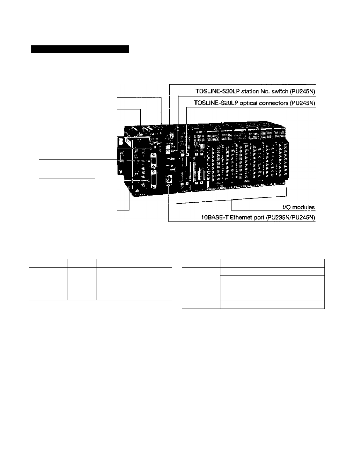
T2N CPU Unit Configuration
Network status indicators (PU235N/PU245N)
CPU module
Power supply module
CPU status indicators
_________
Operation mode switch
Programiner port (RS-232C]
RS-232C/RS-4S5
communication port
_____
Rack
T2N basic components
Item Type Description
CPU module
PU215N
PU236N
23,5 k steps, standard type
Standard ptua Ethernet
PU245N
Standard plus Ethernet
and TOSL1NE-S20LP
Item
Type Description
Power supply
moduie
PS261 j 100 to 240 Vac
PS31 1 24 Vdc
CPU rack BU228N 1 8 I/O slots
Expansion
rack
BU268
8 I/O slots
BU266 5 I/O slots
• The RS-232C/RS-485 communication port (D-Sub 15-pin femaie connector) is built-in the T2N CPU module.
The interface, RS-232C or RS-485, is selected by the switch provided on the CPU module. This port has the
same function as the optional communication cards (CM231E or CM232E) on the T2E CPU.
• The PU235N has all the PU215N functions plus Ethernet (10BASE-T) interface.
• The PU245N has all the PU215N functions plus Ethernet (10BASE-T) interface and the TOSLINE-S20LP
interface,
• Each T2N CPU module comes with a battery,
• The T2N CPU module can be mounted only in the BU228N rack.
• The BU266 and the BU26B can be used only for the expansion racks with the T2N.
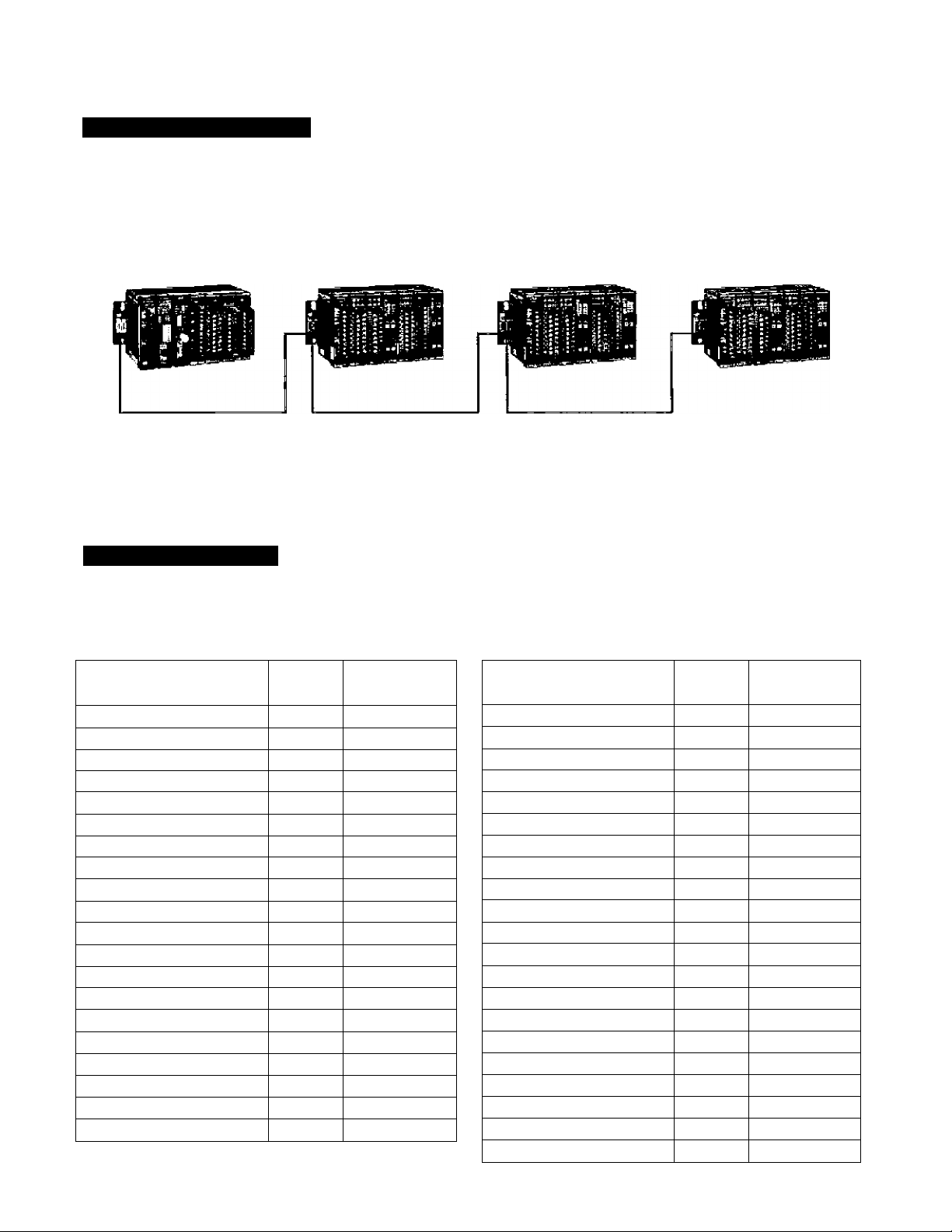
Expansion Configuration
up to three expansion racKs (BU266 or BU26S) can be connected to the T2&T2N CPU rack. In the maximum
configuration, the T2E/T2N provides 32 slots for I/O modules.
CPU unit
Expansion unit #1 Expansion unit #2
Expansion unit #3
A power supply module is nec^sary in each rack.
' The following expansion cables are ayailable; 30 cm, 50 cm, 70 cm and 1.5 m.
■ The total cable length cannot exceed 4.5 m.
Power Supply Check
The power supply module can output maximum 2,5 A {5 Vdc) to power the Internal logic of the modules. Check
that the internal current consumption of the modules on a rack is less than the 2,5 A maximum.
The list below shows the internal current consumption of each module.
Item ' Type
Internal 5 Vdc
oonsumptÈon
T2ECPU
PU234E SOD mA or less
T2E optional
CM231E 200 tnA or less
communication card CM232E 200 mA or less
T2N CPU
PU215N SOD mA or less
PU236N
1.5 A or less
PU245N 2.0 A or less
CPU rack tor T2E BU218 50 mA or less
UBB2 50 mA or iess
UBDI
50 mA or less
U8A2 50 mA or less
UBAI 60 mA or less
CPU rack forT2N
BU223N SD mA or less
Expansion rack BU263 60 mA or less
BU266 50 mA or less
16 points DC input DI31
15 mA or l^s
32 points DC input
DI32 80 mA or less
64 points DC Input
DI235 100 mA or less
16 points AC Input
IN51
15 mA or less
IN61 15 mA or less
12 points relav output R061
50 mA or less
Item Type Intanai 5 Vdc
consumption
8 points relay output R062
40 mA or less
16 points transistor output D031
60 mA or less
D0233P
60 mA or less
32 points transistor output D032 250 mA or less
04 points transistor output
D0235 250 mA or less
12 points trtac output AC61 300 mA or less
4 chantieis analog input
AI21
50 mAor less
AI31 50 mA or less
AI22
50 mA or less
AÌ32
50 mA or lass
2 channels analog output
A031 70 mA or leas
A022 170 mAor less
A032
170 mAor less
1 channel pulse input
PI21 80 mA or less
1 axis position control
Mcn
200 rnA or less
Communication interface CF211
550 mA or less
TOSLINE-S20 (coaxial)
SN221 600 mA or less
TOSLINE-S20 (optical) SN222A 700 mA or less
TOSLINE-F10 (master) MS211
600 mA or less
TOSLIME-F10 (remote)
RS211 60D mA or less
DevIceNet scanner
DN211
500 mA or less
Flexible Serial Port
Programmer Port
The T2E/T2N’s RS-232C programmer port supports the open T-sprles computer linK protocol as well as the
proprietary programmer protocol. This próvidas an easy connection to a higher level computer, an operator
interface unit, a modem, etc.
Master computer
Operator interface
^
_____
I .
IlwHiKilKIjEr
T2BT2N
Modem
Telephorre lirve
Modem
Interface RS-232C
Transmission system Half-duplex
Transmission speed 36D0 bps
Framing Start bit: 1 bit
Data bits; B bits
Parity: Odd or none
Stop bit: 1 bit
Protocol
Computer (ink protocol.
Programmer protocol
T2BT2N
Communication Port on the CPU Module
The RS-232C or RS-485 multi-purpose communication port is standard on the T2N CPU. The interface is
selected by a DIP switch.
The RS-232C or RS-4S5 multi-purpose communication port is an option on the T2E CPU. A CM231E or
CMI232E card must be mounted in the T2E CPU module.
By using these communication port, one of the follow'lng three communication modes is available.
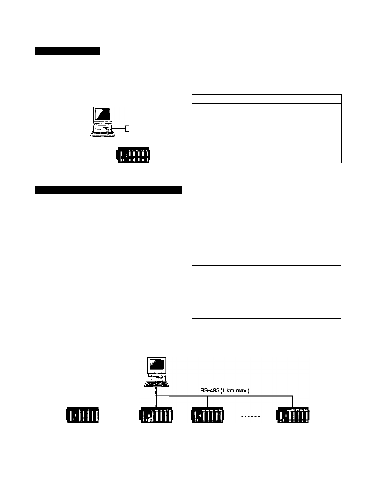
Computer link mode
T-sertes computer link protocol can be used in this
mode. When the RS-485 is used, a maximum of 32
T2E/T2NS can be connected to a master computer.
By using this mode, all the T2E/T2N's data can be
accessed by a master computer.
The T-series PLC programming software fT-PDS}
can also he used in this configuration.
Transmission system
Half-duplex
Transmission speed
300/600/1200/2400/
4800/9600/19200 bps
Framing
Stsfl bit: 1 bit
Data bits: 7 or 6 bits
Parity: Odd/ewen/none
Stop bit: 1 or 2 bits
Protocol Computer link protocol,
Programmer protocof
Master computer
Waster computer
RS-23X {15 rr max.)
T2E/T2N T2&T2N T2E/T2N
T2BT2N
32 T2E/T2t4s max.
Communication Port on the CPU Module
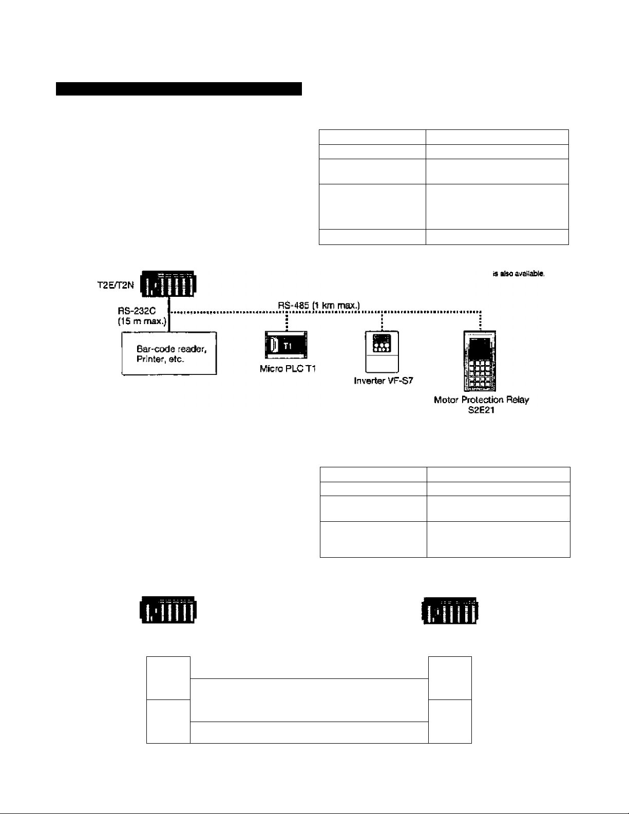
Free ASCII mode
User defined ASCII messages can be transmitted
and received through this port. A termini, printer,
bar-code reader, or other serial ASCII device can be
directly connected.
Шз mode allows the T2E/T2N to communicate with
other PLCs 0Г1, T2E. T2N. etc.). Inverters (3uch as
VF-S7/A5, G3), or Motor protection relays (S2E21).
Transmission system
Half'duplex
Transmission code ASCII
Transmission speed
300/600/1200/2400/
4800/9600/19200 bps
Framing
bit; 1 bit
Data bits: 7 or B bits
Parity; OdcVeven/nofie
Stop bit; 1 or 2 bits
Message (ength
512 bytes max.
Mete) RS-A^B5 2-wirs sy^sm
Data link mode
Two PLCs (any combination of T2E, T2N or Super
T1-40) can be directly linked together. This direct
link is inexpensive, easily configured and requires no
special programming. File registers FOOOO to F0Q31
are used for the data transfer.
Transmt^ion speed
19200 bps
Protocol Special
Link data capacity
16 words (station 1 to 2)
16 words (station 2 to 1)
Link data update time
approx. 50 ms
(not synchronized with
T2E/T2NS scan)
T^E orT2N
RS-232C (15 m max.)
RS-485 (1 l«n max.)
T2EorT2N
Station No.1
Station No,2
FO^
FOOOO
FOOIS
F0015
F0016
F0016
F0031
F0031
Loading...