


6F3B0253
UM-TS01 -E031
PROGRAMMABLE CONTROLLER
PROSEC T116S
USER’S MANUAL
−− Basic Hardware and Function−−
TOSHIBA CORPORATION
CTi Automation - Phone: 800.894.0412 - Fax: 208.368.0415 - Web: www.ctiautomation.net - Email: info@ctiautomation.net
6F3B0253
Important Information
Misuse of this equipment can result in property damage or human injury. Because controlled system applications vary widely, you should satisfy yourself as to the acceptability of this equipment for your intended purpose.
In no event will Toshiba Corporation be responsible or liable for either indirect
or consequential damage or injury that may result from the use of this equipment.
No patent liability is assumed by Toshiba Corporation with respect to use of information, illustrations, circuits, equipment or examples of application in this publication.
Toshiba Corporation reserves the right to make changes and improvements to this publication and/or related products at any time without notice. No obligation shall be incurred other than as noted in this publication.
This publication is copyrighted and contains proprietary material. No part of this book may be reproduced, stored in a retrieval system, or transmitted, in any form or by any means electrical, mechanical, photocopying, recording, or otherwise without obtaining prior written permission from Toshiba Corporation.
© TOSHIBA Corporation 2001. All rights reserved
IBM is a registered trademark of International Business Machines Corporation. MS-DOS and Windows are registered trademarks of Microsoft Corporation.
Publication number: UM-TS01 -E031
1st edition April 2001, 2nd edition November 2001
CTi Automation - Phone: 800.894.0412 - Fax: 208.368.0415 - Web: www.ctiautomation.net - Email: info@ctiautomation.net

6F3B0253
CE Marking
The Programmable Controller PROSEC T1-16S (hereafter called T1-16S) complies with the requirements of the EMC Directive 89/336/EEC and Low Voltage Directive 72/23/EEC under the condition of use according to the instructions described in this manual.
The contents of the conformity are shown below.
Application of |
EMC : |
89/336/EEC (as amended by 91/263/EEC and 92/31/EEC) |
||
Council Directive |
LVD |
: |
72/23/EEC (as amended by 93/68/EEC) |
|
Manufacture’s Name |
|
: |
Toshiba Corporation, |
|
|
|
|
Fuchu Operations-Social Infrastructure Systems |
|
Address |
|
: |
1, Toshiba-Cho |
|
|
|
|
Fuchu-shi |
|
|
|
|
TOKYO 183-8511 |
|
|
|
|
Japan |
|
declares, that the product |
|
|
|
|
Product Name |
|
: |
Programmable Controller , T1-16S |
|
Model Number |
|
: |
TDR116S6S, TDR116S6C |
|
|
|
|
TDR116S3S, TDR116S3C |
|
conforms to the following Product Specifications: |
|
|||
EMC |
|
|
|
|
Radiated Interference |
|
: |
EN 55011 Group 1 Class A |
|
Mains Interference |
|
: |
EN 55011 Group 1 Class A |
|
Radiated Susceptibility |
|
: |
ENV50140 |
|
Conducted RFI Susceptibility |
: |
ENV50141, IEC100-4-6. |
|
|
Electrostatic Discharge |
|
: |
IEC1000-4-2 |
|
Electrical Fast Transient |
|
: |
IEC1000-4-4 |
|
LVD |
|
: |
EN61131-2:1995 3.10 |
Dielectric Properties |
|
|
|
4. |
Mechanical Requirements |
Supplementary information |
: |
|
|
|
(1)Included Handy Programmer THP911A*S.
(2)Included each type of associated input/output unit in a typical configuration.
(3)Product must be installed in accordance with manufacturers instructions
Basic Hardware and Function 1
CTi Automation - Phone: 800.894.0412 - Fax: 208.368.0415 - Web: www.ctiautomation.net - Email: info@ctiautomation.net

6F3B0253
UL/c-UL Listing
The Programmable Controller PROSEC T1-16S (hereafter called T1-16S) is UL/c-UL listed as shown below.
UL and c-UL Listing |
|
File Number : |
E95637 |
Product Name : |
Programmable Controller , T1-16S |
Product Covered : |
Main Unit |
|
TDR116S6S, TDR116S6C, |
|
TDR116S3S, TDR116S3C |
|
I/O module |
|
TDI116M*S, TDD116M*S, TDO116M*S, |
|
TAD121M*S, TAD131M*S, TDA121M*S, TDA131M*S, |
|
TFR112M*S |
|
Peripherals |
|
TRM102**S, TCU111**S, THP911A*S |
UL and c-UL Listing For Use in Hazardous Locations |
|
File Number : |
E184034 |
Product Name : |
Programmable Controller , T1-16S |
Product Covered : |
Main Unit |
|
TDR116S6S, TDR116S6C |
Locations Class : |
Class I, Division 2, Groups A, B, C, D |
Important Notice : 1. THIS EQUIPMENT IS SUITABLE FOR USE IN CLASS I,
DIVISION 2, GROUPS A, B, C, D OR NON-HAZARDOUS
LOCATIONS ONLY.
2.WARNING - EXPLOSION HAZARD - SUBSTITUTION OF COMPONENTS MAY IMPAIR SUITABILITY FOR CLASS I, DIVISION 2.
3.WARNING - EXPLOSION HAZARD - DO NOT DISCONNECT EQUIPMENT UNLESS POWER HAS BEEN SWITCHED OFF OR THE AREA IS KNOWN TO BE NON-HAZARDOUS.
2 T1-16S User’s Manual
CTi Automation - Phone: 800.894.0412 - Fax: 208.368.0415 - Web: www.ctiautomation.net - Email: info@ctiautomation.net

6F3B0253
Safety Precautions
This manual is prepared for users of Toshiba’s Programmable Controller T1-16S.
Read this manual thoroughly before using the T1-16S. Also, keep this manual and related manuals so that you can read them anytime while the T1-16S is in operation.
General Information
1.The T1-16S has been designed and manufactured for use in an industrial environment. However, the T1-16S is not intended to be used for systems which may endanger human life. Consult Toshiba if you intend to use the T1-16S for a special application, such as transportation machines, medical apparatus, aviation and space systems, nuclear controls, submarine systems, etc.
2.The T1-16S has been manufactured under strict quality control. However, to keep safety of overall automated system, fail-safe systems should be considered outside the T1-16S.
3.In installation, wiring, operation and maintenance of the T1-16S, it is assumed that the users have general knowledge of industrial electric control systems.
If this product is handled or operated improperly, electrical shock, fire or damage to this product could result.
4.This manual has been written for users who are familiar with Programmable Controllers and industrial control equipment. Contact Toshiba if you have any questions about this manual.
5.Sample programs and circuits described in this manual are provided for explaining the operations and applications of the T1-16S. You should test completely if you use them as a part of your application system.
Hazard Classifications
In this manual, the following two hazard classifications are used to explain the safety precautions.
!WARNING
!CAUTION
Indicates a potentially hazardous situation which, if not avoided, could result in death or serious injury.
Indicates a potentially hazardous situation which, if not avoided, may result in minor or moderate injury. It may also be used to alert against unsafe practices.
Even a precaution is classified as CAUTION, it may cause serious results depending on the situation. Observe all the safety precautions described on this manual.
Basic Hardware and Function 3
CTi Automation - Phone: 800.894.0412 - Fax: 208.368.0415 - Web: www.ctiautomation.net - Email: info@ctiautomation.net

6F3B0253
Safety Precautions
Installation:
!CAUTION
1.Excess temperature, humidity, vibration, shocks, or dusty and corrosive gas environment can cause electrical shock, fire or malfunction. Install and use the T116S and related equipment in the environment described in this manual.
2.Improper installation directions or insufficient installation can cause fire or the units to drop. Install the T1-16S and related equipment in accordance with the instructions described in this manual.
3.Turn off power before installing or removing any units, modules, racks, terminal blocks or battery. Failure to do so can cause electrical shock or damage to the T116S and related equipment.
4.Entering wire scraps or other foreign debris into to the T1-16S and related equipment can cause fire or malfunction. Pay attention to prevent entering them into the T1-16S and related equipment during installation and wiring.
5.Turn off power immediately if the T1-16S or related equipment is emitting smoke or odor. Operation under such situation can cause fire or electrical shock. Also unauthorized repairing will cause fire or serious accidents. Do not attempt to repair. Contact Toshiba for repairing.
Wiring:
!CAUTION
1.Turn off power before wiring to minimize the risk of electrical shock.
2.Exposed conductive parts of wire can cause electrical shock. Use crimp-style terminals with insulating sheath or insulating tape to cover the conductive parts. Also close the terminal covers securely on the terminal blocks when wiring has been completed.
3.Operation without grounding may cause electrical shock or malfunction. Connect the ground terminal on the T1-16S to the system ground.
4.Applying excess power voltage to the T1-16S can cause explosion or fire. Apply power of the specified ratings described in the manual.
5.Improper wiring can cause fire, electrical shock or malfunction. Observe local regulations on wiring and grounding.
4 T1-16S User’s Manual
CTi Automation - Phone: 800.894.0412 - Fax: 208.368.0415 - Web: www.ctiautomation.net - Email: info@ctiautomation.net

6F3B0253
Safety Precautions
Operation:
!WARNING
1.Configure emergency stop and safety interlocking circuits outside the T1-16S. Otherwise, malfunction of the T1-16S can cause injury or serious accidents.
!CAUTION
2.Operate the T1-16S and the related modules with closing the terminal covers. Keep hands away from terminals while power on, to avoid the risk of electrical shock.
3.When you attempt to perform force outputs, RUN/HALT controls, etc. during operation, carefully check for safety.
4.Turn on power to the T1-16S before turning on power to the loads. Failure to do so may cause unexpected behavior of the loads.
5.Do not use any modules of the T1-16S for the purpose other than specified. This can cause electrical shock or injury.
6.Do not modify the T1-16S and related equipment in hardware nor software. This can cause fire, electrical shock or injury.
7.Configure the external circuit so that the external 24 Vdc power required for transistor output circuits and power to the loads are switched on/off simultaneously. Also, turn off power to the loads before turning off power to the T1-16S.
8.Install fuses appropriate to the load current in the external circuits for the outputs. Failure to do so can cause fire in case of load over-current.
9.Check for proper connections on wires, connectors and modules. Insufficient contact can cause malfunction or damage to the T1-16S and related equipment.
Basic Hardware and Function 5
CTi Automation - Phone: 800.894.0412 - Fax: 208.368.0415 - Web: www.ctiautomation.net - Email: info@ctiautomation.net

6F3B0253
Safety Precautions
Maintenance:
!CAUTION
1.Turn off power before removing or replacing units, modules, terminal blocks or wires. Failure to do so can cause electrical shock or damage to the T1-16S and related equipment.
2.When you remove both input and output terminal blocks with wires for maintenance purpose, pay attention to prevent inserting them upside down.
3.Touch a grounded metal part to discharge the static electricity on your body before touching the equipment.
4.Otherwise, charged static electricity on your body can cause malfunction or failure.
5.Do not disassemble the T1-16S because there are hazardous voltage parts inside.
6.Perform daily checks, periodical checks and cleaning to maintain the system in normal condition and to prevent unnecessary troubles.
7.Check by referring “Troubleshooting” section of this manual when operating improperly. Contact Toshiba for repairing if the T1-16S or related equipment is failed. Toshiba will not guarantee proper operation nor safety for unauthorized repairing.
8.The contact reliability of the output relays will reduce if the switching exceeds the specified life. Replace the unit or module if exceeded.
9.The battery used in T1-16S may present a risk of fire of chemical burn if mistreated. Do not recharge, disassemble, heat above 100ºC (212ºF), or incinerate.
10.Replace battery with CR2032 only. Use of another battery may present a risk of fire or explosion.
11.Dispose of used battery promptly. Keep away from children. Do not disassemble and do not dispose of in fire.
6 T1-16S User’s Manual
CTi Automation - Phone: 800.894.0412 - Fax: 208.368.0415 - Web: www.ctiautomation.net - Email: info@ctiautomation.net
6F3B0253
Safety Precautions
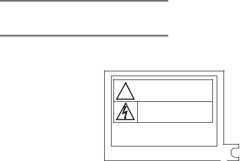
Safety Label
The safety label as shown on the right is attached to the power terminal of the T1-16S.
Remove the mount paper before wiring.
Peel off the label from the mount paper and stick it near the power terminals where it can be readily seen.
! CAUTION
Do not touch terminals while power on.
Hazardous voltage can shock, burn or cause death. Do not touch terminals while power on.
Read related manual thoroughly for safety. Stick this seal on unit or near unit.
Take off this sheet before wiring.
Contact Toshiba if the label is damaged.
Basic Hardware and Function 7
CTi Automation - Phone: 800.894.0412 - Fax: 208.368.0415 - Web: www.ctiautomation.net - Email: info@ctiautomation.net

6F3B0253
About This Manual
About This Manual
This manual has been prepared for first-time users of Toshiba’s Programmable Controller T1-16S to enable a full understanding of the configuration of the equipment, and to enable the user to obtain the maximum benefits of the equipment.
This manual introduces the T1-16S, and explains the system configuration, specifications, installation and wiring for T1-16S’s basic hardware. This manual provides the information for designing T1-16S user program, such as the internal operation, memory configuration, I/O allocation and programming instructions. Information for maintenance and troubleshooting are also provided in this manual.
The T1-16S’s computer link function and T1-16S’s multi-purpose communication functions are covered by the separate manual. Read the T1-16S User’s Manual - Communication Function - for details.
Inside This Manual
This manual consists of 10 main sections and an appendix.
Section 1 outlines the T1-16S configuration. To fully understand the T1-16S, it is important to read this section carefully. Sections 2, to 4 describe the hardware used in designing external circuits and panels. Sections 5 to 7 are mainly concerned with software. Section 8 explains the T1-16S’s special I/O functions. Sections 9 and 10 describe the maintenance procedure for the T1-16S, to ensure safe operation and long service life.
Related Manuals
The following related manuals are available for T1-16S. Besides this manual, read the following manuals for your better understanding.
T1-16S User’s Manual |
|
- Basic Hardware and Function - (this manual) |
UM-TS01 -E031 |
- I/O Modules - |
UM-TS01 -E034 |
- Communication Function - |
UM-TS01 -E033 |
T-Series Handy Programmer (HP911) Operation Manual |
UM-TS03 -E025 |
T-Series Program Development System (T-PDS) User’s Manual |
UM-TS03 -E045 |
8 T1-16S User’s Manual
CTi Automation - Phone: 800.894.0412 - Fax: 208.368.0415 - Web: www.ctiautomation.net - Email: info@ctiautomation.net
6F3B0253
About This Manual
Terminology
The following is a list of abbreviations and acronyms used in this manual.
s |
microsecond |
ASCII |
American Standard Code For Information Interchange |
AWG |
American Wire Gage |
BCC |
Block Check Code |
CCW |
Counter-Clockwise |
CPU |
Central Processing Unit |
CW |
Clockwise |
EEPROM |
Electrically Erasable Programmable Read Only Memory |
H |
hexadecimal (when it appears in front of an alphanumeric string) |
I/O |
Input/Output |
LED |
Light Emitting Diode |
LSB |
Least Significant Bit |
ms |
millisecond |
MSB |
Most Significant Bit |
PWM |
Pulse Width Modulation |
RAM |
Random Access Memory |
ROM |
Read Only Memory |
Vac |
AC voltage |
Vdc |
DC voltage |
Basic Hardware and Function 9
CTi Automation - Phone: 800.894.0412 - Fax: 208.368.0415 - Web: www.ctiautomation.net - Email: info@ctiautomation.net

|
|
6F3B0253 |
Contents |
|
|
Contents |
|
|
Safety Precautions .................................................................................. |
3 |
|
About This Manual .................................................................................. |
8 |
|
1. |
System Configuration .................................................................... |
13 |
1.1 |
Introducing the T1-16S ................................................................ |
14 |
1.2 |
Features .............................................................................................. |
16 |
1.3 |
System configuration .......................................................................... |
19 |
1.4 |
I/O expansion ...................................................................................... |
20 |
1.5 |
Components ........................................................................................ |
21 |
1.5.1 |
Basic unit ......................................................................................... |
21 |
1.5.2 |
I/O modules ...................................................................................... |
25 |
1.5.3 |
Options ............................................................................................ |
26 |
1.6 |
Programmer port function .................................................................. |
27 |
1.7 |
RS-485 port communication function ................................................. |
28 |
1.8 |
Real-time data link system ................................................................. |
32 |
1.9 |
Peripheral tools .................................................................................. |
33 |
2. |
Specifications .................................................................................. |
37 |
2.1 |
General specifications ........................................................................ |
38 |
2.2 |
Functional specifications .................................................................... |
40 |
2.3 |
I/O specifications ................................................................................ |
42 |
2.4 |
External dimensions ........................................................................... |
46 |
3. |
I/O Application Precautions .......................................................... |
47 |
3.1 |
Application precautions for input signals ............................................ |
48 |
3.2 |
Application precautions for output signals .......................................... |
50 |
4. |
Installation and Wiring ................................................................... |
53 |
4.1 |
Environmental conditions ................................................................... |
54 |
4.2 |
Installing the unit ................................................................................. |
55 |
4.3 |
Wiring terminals .................................................................................. |
57 |
4.4 |
Grounding ........................................................................................... |
58 |
4.5 |
Power supply wiring ............................................................................ |
59 |
4.6 |
I/O wiring ............................................................................................ |
61 |
10 T1-16S User’s Manual
CTi Automation - Phone: 800.894.0412 - Fax: 208.368.0415 - Web: www.ctiautomation.net - Email: info@ctiautomation.net

|
|
6F3B0253 |
|
|
Contents |
5. |
Operating System Overview |
......................................................... 63 |
5.1 |
Operation modes ................................................................................ |
64 |
5.2 |
About the built-in EEPROM ................................................................ |
66 |
5.3 |
Scanning ............................................................................................. |
69 |
6. |
Programming Information ............................................................. |
73 |
6.1 |
Devices and registers ......................................................................... |
74 |
6.2 |
Index modification ............................................................................... |
86 |
6.3 |
Real-time clock/calendar .................................................................... |
88 |
6.4 |
I/O allocation ....................................................................................... |
89 |
6.5 |
T1-16S memory mode setting.............................................................. |
91 |
6.6 |
User program configuration ................................................................ |
92 |
6.6.1 |
Main program .................................................................................. |
94 |
6.6.2 |
Sub-program #1 .............................................................................. |
95 |
6.6.3 |
Timer interrupt program .................................................................. |
95 |
6.6.4 |
I/O interrupt programs ..................................................................... |
96 |
6.6.5 |
Subroutines .................................................................................... |
97 |
6.7 |
Programming language ...................................................................... |
98 |
6.8 |
Program execution sequence ............................................................ |
99 |
6.9 |
On-line debug support functions ........................................................ |
100 |
6.10 |
Password protection ........................................................................... |
103 |
7. |
Instructions ...................................................................................... |
105 |
7.1 |
List of instructions .............................................................................. |
106 |
7.2 |
Instruction specifications .................................................................... |
116 |
8. |
Special I/O Functions .................................................................... |
255 |
8.1 |
Special I/O function overview ............................................................. |
256 |
8.2 |
Variable input filter constant .............................................................. |
260 |
8.3 |
High speed counter ............................................................................ |
261 |
8.3.1 |
Single phase up-counter ................................................................. |
262 |
8.3.2 |
Single phase speed-counter ............................................................ |
263 |
8.3.3 |
Quadrature bi-pulse counter ............................................................ |
265 |
8.4 |
Interrupt input function ........................................................................ |
268 |
8.5 |
Analog setting function ....................................................................... |
270 |
8.6 |
Pulse output function .......................................................................... |
271 |
8.7 |
PWM output function .......................................................................... |
273 |
9. |
Maintenance and Checks .............................................................. |
275 |
9.1 |
Precautions during operation ............................................................. |
276 |
9.2 |
Daily checks ........................................................................................ |
277 |
9.3 |
Periodic checks ................................................................................... |
278 |
9.4 |
Maintenance parts ............................................................................... |
279 |
9.5 |
Battery ................................................................................................. |
280 |
|
|
Basic Hardware and Function 11 |
CTi Automation - Phone: 800.894.0412 - Fax: 208.368.0415 - Web: www.ctiautomation.net - Email: info@ctiautomation.net

|
|
6F3B0253 |
Contents |
|
|
10. |
Troubleshooting .............................................................................. |
281 |
10.1 |
Troubleshooting procedure ................................................................ |
282 |
10.1.1 |
Power supply check ......................................................................... |
283 |
10.1.2 |
CPU check ....................................................................................... |
284 |
10.1.3 |
Program check ................................................................................. |
284 |
10.1.4 |
Input check ....................................................................................... |
285 |
10.1.5 |
Output check .................................................................................... |
286 |
10.1.6 |
Environmental problem .................................................................... |
287 |
10.2 |
Self-diagnostic items .......................................................................... |
288 |
Appendix ......................................................................................................... |
293 |
|
A.1 |
List of models and types ..................................................................... |
294 |
A.2 |
Instruction index ................................................................................. |
295 |
12 T1-16S User’s Manual
CTi Automation - Phone: 800.894.0412 - Fax: 208.368.0415 - Web: www.ctiautomation.net - Email: info@ctiautomation.net

6F3B0253
Section 1
System Configuration
1.1Introducing the T1-16S, 14
1.2Features, 16
1.3System configuration, 19
1.4I/O expansion, 20
1.5Components, 21
1.6Computer link system, 27
1.7T1-16S Communication function, 28
1.8Real-time data link system, 32
1.9Peripheral tools, 33
Basic Hardware and Function 13
CTi Automation - Phone: 800.894.0412 - Fax: 208.368.0415 - Web: www.ctiautomation.net - Email: info@ctiautomation.net
6F3B0253
1. System Configuration
1.1 Introducing the T1-16S
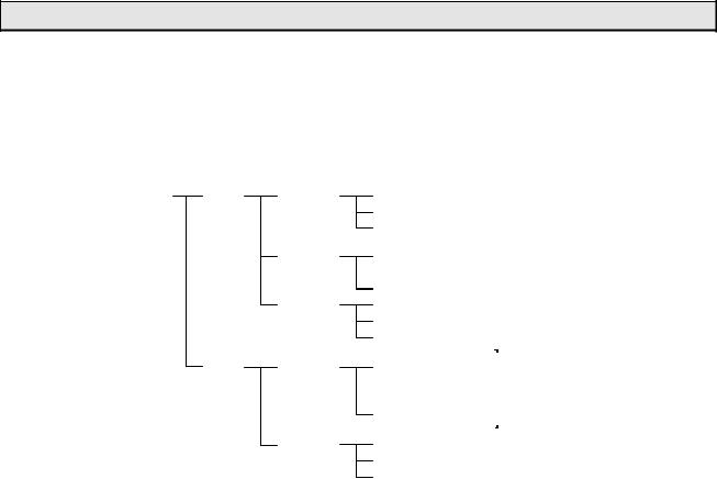
The T1-16 is compact, block style, high-performance programmable controller with a range of 16 to 144 input and output points.
The figure below shows the T1 Series line-up. The T1 Series consists of the total 16 types.
T1 Series |
T1 |
|
|
T1-16 |
|
|
|
|
|
|
|
|
|
T1-MDR16 |
|
|
|||||||||||||||||||||||||||||||
|
|
|
|
|
|
|
|
|
|
|
|
|
|
|
|
|
|
|
|
|
|
|
|
T1-MAR16 |
|
|
|||||||||||||||||||||
|
|
|
|
|
|
|
|
|
|
|
|
|
|
|
|
|
|
|
|
|
|
|
|
T1-MDR16D |
|
|
|||||||||||||||||||||
|
|
|
|
|
T1-28 |
|
|
|
|
|
|
|
|
|
T1-MDR28 |
|
|
||||||||||||||||||||||||||||||
|
|
|
|
|
|
|
|
|
|
|
|
|
|
|
|
|
|
|
|
|
|
|
|
T1-MAR28 |
|
|
|||||||||||||||||||||
|
|
|
|
|
|
|
|
|
|
|
|
|
|
|
|
|
|
|
|
|
|
|
|
|
|
||||||||||||||||||||||
|
|
|
|
|
|
|
|
|
|
|
|
|
|
|
|
|
|
|
|
|
|
|
|
T1-MDR28D |
|
|
|||||||||||||||||||||
|
|
|
|
|
T1-40 |
|
|
|
|
|
|
|
|
|
T1-MDR40 |
|
|
||||||||||||||||||||||||||||||
|
|
|
|
|
|
|
|
|
|
|
|
|
|
|
|
|
|
|
|
|
|
|
|
T1-MAR40 |
|
|
|||||||||||||||||||||
|
|
|
|
|
|
|
|
|
|
|
|
|
|
|
|
|
|
|
|
|
|
|
|
T1-MDR40D |
|
|
|||||||||||||||||||||
|
|
|
|
|
|
|
|
|
|
|
|
|
|
|
|
|
|
|
|
|
|
|
|
|
|
|
|
|
|
|
|
|
|
|
|
|
|
|
|
|
|
|
|
|
|
|
|
|
T1S |
|
|
|
T1-16S |
|
|
|
|
|
|
|
|
|
T1-MDR16SS |
|
|
||||||||||||||||||||||||||||||
|
|
|
|
|
|
|
|
|
|
|
|
|
|
|
|
|
|
|
|
|
|
|
|
T1-MDR16SC |
|
|
|||||||||||||||||||||
|
|
|
|
|
|
|
|
|
|
|
|
|
|
|
|
|
|
|
|
|
|
|
|
T1-MDR16SSD |
|
|
|||||||||||||||||||||
|
|
|
|
|
|
|
|
|
|
|
|
|
|
|
|
|
|
|
|
|
|
|
|
T1-MDR16SCD |
|
|
|||||||||||||||||||||
|
|
|
|
|
|
|
|
|
|
|
|
|
|
|
|
|
|
|
|
|
|
|
|
|
|
||||||||||||||||||||||
|
|
|
|
|
|
|
|
|
|
|
|
|
|
|
|
|
|
|
|
|
|
|
|
|
|
|
|
|
|
|
|
|
|
|
|
|
|
|
|
|
|
|
|
|
|
|
|
|
|
|
|
|
T1-40S |
|
|
|
|
|
|
|
|
|
T1-MDR40S |
|
|
||||||||||||||||||||||||||||||
|
|
|
|
|
|
|
|
|
|
|
|
|
|
|
|
|
|
|
|
|
|
|
|
T1-MAR40S |
|
|
|||||||||||||||||||||
|
|
|
|
|
|
|
|
|
|
|
|
|
|
|
|
|
|
|
|
|
|
|
|
T1-MDR40SD |
|
|
|||||||||||||||||||||
I/O points:
The T1 Series are available in five models, T1-16, T1-28, T1-40, T1-40S and T116S. Each model has the following I/O points.
|
T1-16 |
T1-16S |
T1-28 |
T1-40 |
T1-40S |
Input |
8 points |
|
14 points |
24 points |
|
|
|
|
|
|
|
Output |
8 points |
|
14 points |
16 points |
|
|
(6 relay plus 2 slid-state) |
(12 relay plus |
(14 relay plus 2 solid-state) |
||
|
|
|
2 slid-state) |
|
|
Expansion |
No |
Up to 8 I/O |
No |
2 option cards plus |
|
|
|
modules. |
|
1 expansion rack or unit. |
|
|
|
Total up to |
|
Total up to 382 points. |
|
|
|
144 points. |
|
|
|
The T1-16S can expand its I/O points by connecting I/O modules. Up to eight I/O modules can be connected. If eight 16-point I/O modules are connected to the T116S, it can control up to 144 points.
14 T1-16S User’s Manual
CTi Automation - Phone: 800.894.0412 - Fax: 208.368.0415 - Web: www.ctiautomation.net - Email: info@ctiautomation.net

6F3B0253
1. System Configuration
Memory capacity:
Program memory capacity of the T1 is 2 k steps. And that of the T1S is 8 k steps. Whole the program and a part of data registers are stored in built-in EEPROM.
|
T1-16/28/40 |
|
T1-40S |
|
T1-16S |
Memory |
RAM (for execution) and EEPROM (for back-up) |
||||
Program |
2 k steps |
|
8 k steps |
|
|
capacity |
|
|
(4 k mode or 8 k mode) |
||
Data capacity |
Auxiliary relay: 1024 points |
Auxiliary relay: |
4096 points |
||
|
Timer: |
64 points |
Timer: |
256 points |
|
|
Counter: |
64 points |
Counter: |
256 points |
|
|
Data register: |
1024 words |
Data register: |
4096 words |
|
EEPROM |
Program and leading 512 |
Program and the user specified range of |
|||
back-up |
words of Data register |
Data register (0 to 2048 words) |
|||
RAM back-up |
Capacitor: 6 hours or more |
Capacitor: 168 hours |
Capacitor: 1 hour |
||
(at 25°C) |
|
|
or more |
|
or more |
(at 77°F) |
|
|
|
|
Battery: 2 years |
|
|
|
|
|
or more |
Control functions:
In addition to the basic relay ladder functions, the T1/T1S provides functions such as data operations, arithmetic operations, various functions, etc. Furthermore, its highspeed counter functions, pulse output functions and data communication functions allow its application to a wide scope of control systems.
|
T1-16/28/40 |
T1-40S |
|
T1-16S |
|
|
Language |
Ladder diagram with function block |
|
|
|||
Number of |
Basic: |
17 types |
Basic: |
21 types |
Basic: |
21 types |
instructions |
Function: |
76 types |
Function: |
99 types |
Function: |
97 types |
Subroutines |
16 |
|
256 |
|
|
|
|
(nesting not allowed) |
(up to 3 levels of nesting) |
|
|||
Execution speed |
1.4 s/contact, 2.3 s/coil, 4.2 s/transfer, 6.5 s/addition |
|||||
Real-time |
No |
|
Yes (year, month, day, week, hours, |
|||
clock/calendar |
|
|
minutes, seconds) |
|
|
|
Communication |
RS-232C |
|
RS-232C (programmer port), |
|
||
|
(programmer port) |
RS-485 (multi-purpose) |
|
|||
Construction:
The T1-16S is a compact, easy-handling block style programmable controller. The T1-16S has all of the features of a block style controller. In addition, the T1-16S has modular expandability. The T1-16S provides flexibility into the block style controller.
Series compatibility:
Programming instructions are upward compatible in the T-Series programmable controllers. The T1/T1S programs can be used for other models of the T-Series, T2, T2E, T2N, T3 and T3H. Peripheral tools can also be shared.
Basic Hardware and Function 15
CTi Automation - Phone: 800.894.0412 - Fax: 208.368.0415 - Web: www.ctiautomation.net - Email: info@ctiautomation.net

6F3B0253
1. System Configuration
1.2 Features
I/O module support:
The T1-16S has an interface for connecting the I/O modules. Up to eight modules can be connected to the T1-16S.
By using the 16 points I/O module, the T1-16S can control up to 144 I/O points.
Built-in high-speed counter:
Two single-phase or one quadrature (2-phase) pulses can be counted. The acceptable pulse rate is up to 5 kHz. (DC input type only)
Built-in analog setting adjusters:
Two analog setting adjusters are provided on the T1-16S. This allows operators to adjust time or other control parameters easily using a screwdriver.
High speed processing:
Sophisticated machine control applications require high speed data manipulations. The T1-16S is designed to meet these requirements.
• |
1.4 |
s per contact |
• |
2.3 |
s per coil |
• |
4.2 |
s per 16-bit transfer |
• |
6.5 |
s per 16-bit addition |
The T1-16S also supports interrupt input function (DC input type only). This allows immediate operation independent of program scan.
High performance software:
The T1-16S offers 21 basic ladder instructions and 97 function instructions. Subroutines, Interrupt functions, Indirect addressing, For/Next loops, Pre-derivative real PID, etc. are standard on the T1-16S. These functions allow the T1-16S to be applied to the most demanding control applications.
Battery-less operation:
The T1-16S has a standard built-in EEPROM, permitting operation without need of a battery. Also, the variable data can be written into and/or read from the EEPROM, providing completely maintenance-free back-up operation.
This function is an important feature for OEMs, because it can eliminate the need for changing the battery every few years.
(Optional battery is also available to back-up real-time clock and retentive data)
16 T1-16S User’s Manual
CTi Automation - Phone: 800.894.0412 - Fax: 208.368.0415 - Web: www.ctiautomation.net - Email: info@ctiautomation.net

6F3B0253
1. System Configuration
Pulse output / PWM output:
One point of variable frequency pulses (max. 5 kHz) or variable duty pulses can be output. These functions can be used to drive a stepping motor or to simulate an analog output. (DC input type only)
Built-in computer link function:
The T1-16S’s RS-232C programmer port can accept the computer link protocol (data read/write). This results in easy connection to a higher level computer, an operator interface unit, etc.
The parity setting of the programmer port can be selected either odd or none. The none parity mode is provided especially for telephone modem connection. Using modems, remote programming/monitoring is available.
Real-time control data link network:
By connecting the TOSLINE-F10 remote module (FR112M) to the T1 -16S, highspeed data link network can be established. In this network, upper T-series PLC model (T2/T2E/T2N or T3/T3H) works as master and up to 16 T1-16Ss can be connected as remote. Each T1-16S can exchange data with the master through 1 word input and 1 word output. The transmission speed can be selected either 750 kbps or 250 kbps.
Sampling trace function:
The sampling trace is the function to collect the user specified data every user specified timing (minimum every scan), and to display the collected data on the programmer screen in time chart and/or trend graph format. This function is useful for checking the input signals changing.
Password protection:
By registering your passwords, four levels of protection is available according to the security levels required for your application.
Level 4: Reading/writing program and writing data are prohibited Level 3: Reading/writing program are prohibited
Level 2: Writing program is prohibited
Level 1: No protection (changing passwords is available only in this level)
Two points of solid-state output:
Each model of the T1-16S has two points of solid-state output (transistors for DC input type and triacs for AC input type). These solid-state outputs are suitable for frequent switching application.
Basic Hardware and Function 17
CTi Automation - Phone: 800.894.0412 - Fax: 208.368.0415 - Web: www.ctiautomation.net - Email: info@ctiautomation.net

6F3B0253
1. System Configuration
DIN rail mounting:
The T1-16S is equipped with brackets for mounting on a standard 35 mm DIN rail. The T1-16S can be mounted on a DIN rail as well as screw mounting.
On-line program changes:
When the T1-16S’s memory mode is set to 4 k steps mode, on-line (in RUN mode) program changes are available. Furthermore, program writing into the built-in EEPROM is also available in RUN mode. These functions are useful in program debugging stage.
Real-time clock/calendar function: (Enhanced model only)
The T1-16S has the real-time-clock/calendar function (year, month, day, day of the week, hours, minutes, seconds) that can be used for performing scheduled operations, data gathering with time stamps, etc. To back-up the real-time clock/calendar data, use of the optional battery is recommended.
RS-485 multi-purpose communication port: (Enhanced model only)
The T1-16S has an RS-485 multi-purpose communication port. Using this port, one of the following communication modes can be selected.
••Computer link mode: T-series computer link protocol can be used in this mode. Up to 32 T1-16Ss can be connected to a master computer. By using this mode, MMI/SCADA system can be easily configured.
••Data link mode: Two PLCs (any combination of T1S, T2E or T2N) can be directly linked together. This direct link is inexpensive, easily configured and requires no special programming.
••Free ASCII mode: User defined ASCII messages can be transmitted and received through this port. A terminal, printer, bar-code reader, or other serial ASCII device can be directly connected.
••Inverter connection mode: This mode is specially provided to communicate with Toshiba Inverters (ASDs) VF-A7/G7/S9 series. By using this function, the T1-16S can control and monitor the connected Inverters.
18 T1-16S User’s Manual
CTi Automation - Phone: 800.894.0412 - Fax: 208.368.0415 - Web: www.ctiautomation.net - Email: info@ctiautomation.net

6F3B0253
1. System Configuration
1.3 System configuration
The following figure shows the T1-16S system configuration.
|
|
IBM-PC compatible |
|
|
MMI/SCADA |
personal computer |
Inverter |
Peripheral tool |
system |
|
|
IBM-PC compatible |
|
|
|
personal computer |
|
|
|
RS485 (Standard type only)
T-PDS software
T1-16S basic unit
T1-16S
|
|
|
|
|
|
|
|
|
|
|
Handy programmer |
|
RS232C |
|
|
|
|
|
|
||
|
|
|
|
|
||||||
HP911A |
|
|
|
|
|
|
|
|
||
|
|
|
|
|
|
|
|
|||
|
|
|
|
|
|
|
|
|||
|
|
|
|
|
|
|
|
|
|
|
|
|
|
|
|
|
|
|
|
|
|
|
|
|
|
|
|
|
|
|
|
|
|
|
|
|
|
|
|
|
|
|
|
I/O modules
Computer link function
MMI/SCADA system
8 modules max.
Basic Hardware and Function 19
CTi Automation - Phone: 800.894.0412 - Fax: 208.368.0415 - Web: www.ctiautomation.net - Email: info@ctiautomation.net
6F3B0253
1. System Configuration
1.4 I/O expansion
The T1-16S provides I/O expandability by connecting the I/O modules. Up to eight I/O modules can be connected.
Available I/O modules
DI116M: |
16 points DC input |
DO116M: |
16 points DC output |
DD116M: |
8 points DC input + 8 points DC output |
RO108M: |
8 points relay output |
AD121M: |
1 channel analog input (0 to 5V or 0 to 20mA) |
AD131M: |
1 channel analog input (-10 to +10V) |
DA121M: |
1 channel analog output (0 to 20mA) |
DA131M: |
1 channel analog output (-10 to +10V) |
TC111M: |
1 channel thermocouple input (type K, J, E, or ± 50mV) |
FR112M: |
TOSLINE-F10 remote station |
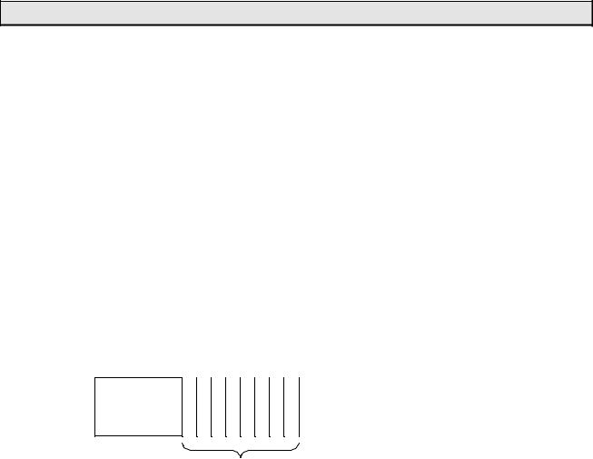
T1-16S maximum configuration
T1-16S main unit
Up to 8 I/O modules
NOTE (1) The 5Vdc power to the I/O modules is supplied from the main unit. The main  unit can supply maximum 1.5A of the 5Vdc power to the I/O modules. Check
the current consumption of each I/O module used. Refer to section 2.1.
(2)The connecting order of the I/O modules is not restricted except TOSLINEF10 remote station FR112M. When the FR112M is used, it must be the right end module.
(3)If more than 8 I/O modules are connected, the T1-16S cannot operate normally.
20 T1-16S User’s Manual
CTi Automation - Phone: 800.894.0412 - Fax: 208.368.0415 - Web: www.ctiautomation.net - Email: info@ctiautomation.net
6F3B0253
1. System Configuration
1.5 Components
1.5.1Basic unit
The T1-16S is available in four types as shown in the following table.
Type |
Link/ Calendar |
Power supply |
Input |
Output |
T1-MDR16SS |
Yes |
100-240 Vac, |
8 points - 24 Vdc |
6 points - relay, |
(Enhanced model) |
50/60 Hz |
|
2 points - transistor |
|
|
|
|||
T1-MDR16SC |
No |
|
|
|
(Standard model) |
|
|
|
|
|
|
|
|
|
T1-MDR16SSD |
Yes |
24 Vdc |
|
|
(Enhanced model) |
|
|
|
|
|
|
|
|
|
T1-MDR16SCD |
No |
|
|
|
(Standard model) |
|
|
|
|
|
|
|
|
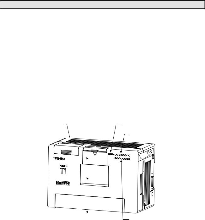
Link terminals (Enhanced model only)
Programmer 
port cover
Battery holder  cover
cover
Power supply and  input/output terminals
Operation status LEDs
I/O status LEDs (Low side)
 Mounting hole
 Expantion
connector
I/O status LEDs (High side)
Basic Hardware and Function 21
CTi Automation - Phone: 800.894.0412 - Fax: 208.368.0415 - Web: www.ctiautomation.net - Email: info@ctiautomation.net
6F3B0253
1. System Configuration
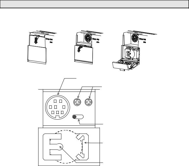
♦ Behind the programmer port cover
Programmer port connector
PRG |
|
V0 |
V1 |
|
H/R |
Analog setting adjusters (V0 and V1)
Mode control switch (HALT / RUN)
Battery holder Battery type: CR2032
(Optional)
A tab for battery eject
Power supply terminals:
Connect the power cable and grounding wire. The terminal screw size is M3. See sections 4.4 and 4.5 for wiring.
Input terminals:
Connect input signal wires. The terminal screw size is M3. See section 2.4 for details.
Output terminals:
Connect output signal wires. The terminal screw size is M3. See section 2.4 for details.
22 T1-16S User’s Manual
CTi Automation - Phone: 800.894.0412 - Fax: 208.368.0415 - Web: www.ctiautomation.net - Email: info@ctiautomation.net

6F3B0253
|
|
1. System Configuration |
||
|
I/O status LEDs: |
|
|
|
|
Indicates the ON/OFF status of each I/O signal. (color: red) |
|
|
|
|
|
|
|
|
|
SW54 setting |
I/O intending for an indication |
Note |
|
|
value |
|
|
|
|
0 (default) |
Basic unit (L: X000-007, H: Y020-027) |
|
|
|
1 |
I/O module slot 0 |
It indicates these at the |
|
|
2 |
I/O module slot 1 |
time of only RUN |
|
|
3 |
I/O module slot 2 |
mode. |
|
|
4 |
I/O module slot 3 |
|
|
|
5 |
I/O module slot 4 |
|
|
|
6 |
I/O module slot 5 |
|
|
|
7 |
I/O module slot 6 |
|
|
|
8 |
I/O module slot 7 |
|
|
|
9 |
TOSLINE-F10 (FR112M), Low 1 word |
|
|
|
10 |
TOSLINE-F10 (FR112M), High 1 word |
|
|
|
Others |
Basic unit (L: X000-007, H: Y020-027) |
|
|
Operation status LEDs:
Indicates the operation status of the T1-16S.
FLT
RUN
PWR
PWR |
|
Lit |
Internal 5 |
Vdc power is normal. |
(Power) (green) |
Not lit |
Internal 5 |
Vdc power is not normal. |
|
RUN |
(green) |
Lit |
RUN mode (in operation) |
|
|
|
Blinking |
HOLD mode |
|
|
|
Not lit |
HALT mode or ERROR mode |
|
FLT |
|
Lit |
ERROR mode |
|
(Fault) |
(red) |
Blinking |
Hardware error (programmer cannot be connected) |
|
|
|
Not lit |
Normal |
|
Mode control switch:
Controls the operation modes of the T1-16S.
H (HALT) |
When the switch is turned to H (HALT) side, the T1-16S stops |
|
program execution (HALT mode). In this position, RUN/HALT |
|
command from the programmer is disabled. |
R (RUN) |
When the switch is turned to R (RUN) side, the T1-16S starts |
|
program execution. This is the position during normal operation. |
|
In this position, RUN/HALT command from the programmer is also |
|
available. |
|
Basic Hardware and Function 23 |
CTi Automation - Phone: 800.894.0412 - Fax: 208.368.0415 - Web: www.ctiautomation.net - Email: info@ctiautomation.net

6F3B0253
1. System Configuration
Analog setting adjusters:
Two analog setting adjusters are provided. The V0 value is stored in SW30 and the V1 value is stored in SW31. The converted value range is 0 to 1000. Refer to section 8.5 for details of the analog setting function.
Programmer port connector:
Used to connect the programmer cable. The interface is RS-232C. This port can also be used for the computer link function. Refer to section 1.6 for more information about the computer link function.
Expansion connector:
Used to connect the I/O module.
RS-485 port (Enhanced model only):
Used to connect a computer (SCADA system), operator interface unit, other T1-16S, or many kinds of serial ASCII devices including Toshiba’s Inverter through RS-485 interface. Refer to section 1.7 for more information about the T1-16S’s RS-485 multipurpose communication functions.
Mounting holes:
Used to fix the T1-16S on a mounting frame by screws. The mounting holes are provided at two opposite corners.
|
Use two M4 screws for mounting. See section 4.2 for |
T1 |
installing the unit. |
|
|
|
|
DIN rail bracket:
The DIN rail bracket is provided at the rear for mounting the T1-16S on a 35 mm DIN rail. See section 4.2 for installing the unit.
24 T1-16S User’s Manual
CTi Automation - Phone: 800.894.0412 - Fax: 208.368.0415 - Web: www.ctiautomation.net - Email: info@ctiautomation.net
6F3B0253
1. System Configuration
1.5.2I/O modules
The T1-16S can connect up to eight I/O modules.
The following 10 types of the I/O modules are available.
For specification details of the I/O modules, refer to the separate manual “T1-16S User’s Manual − I/O Modules − “.
Type |
|
|
|
|
Description |
Power supply |
||
DI116M |
|
|
16 points input, 24Vdc – 5mA |
Supplied from the |
||||
DO116M |
|
|
16 points output, 24Vdc – 100mA |
basic unit (5 Vdc) |
||||
DD116M |
|
|
8 points input, 24Vdc - 5mA |
|
||||
|
|
|
+ 8 points output, 24Vdc – 100mA |
|
||||
RO108M |
|
|
8 points relay output, 24Vdc/240Vac - 1A |
|
||||
AD121M |
|
|
1 channel analog input, 0 to 5V / 0 to 20mA |
|
||||
AD131M |
|
|
1 channel analog input, ± 10V |
|
||||
DA121M |
|
|
1 channel analog output, 0 to 20mA |
|
||||
DA131M |
|
|
1 channel analog output, ± 10V |
|
||||
TC111M |
|
|
1 channel thermo-couple input |
|
||||
FR112M |
|
|
TOSLINE-F10 remote station, |
|
||||
|
|
|
1 word input + 1 word output |
|
||||
|
FR112M |
Other I/O modules |
|
|||||
|
|
|
|
|
|
|
|
|
|
|
|
|
|
|
|
|
|
|
|
Expantion connector |
|
Expantion connectors |
|
||
NOTE |
|
|
|
|
|
|
|
(1) |
If more than 8 I/O modules are connected, T1-16S cannot operate normally. |
||||||
|
|||||||
|
(2) |
The TOSLINE-F10 remote station module (FR112M) must be connected at the |
|||||
|
|
|
right end. Tow or more FR112Ms cannot be used together. |
||||
Basic Hardware and Function 25
CTi Automation - Phone: 800.894.0412 - Fax: 208.368.0415 - Web: www.ctiautomation.net - Email: info@ctiautomation.net

6F3B0253
1.System Configuration
1.5.3Options
The following optional items are available.
Item |
Type |
Description |
|
|
Cable for |
CJ105 |
For T-PDS, 5 m length |
|
|
programming tool |
|
|||
|
|
|
||
Programmer port |
PT16S |
For RS-232C computer link, with 2 m cable |
||
connector |
||||
|
|
|
||
Option card I/O |
PT15S |
Cable side connector for |
Soldering type |
|
connector |
PT15F |
DI116M, DO116M, or DD116M |
Flat cable type |
|
Back-up battery |
CR2032 |
For memory back up. (Available on the market.) |
||
26 T1-16S User’s Manual
CTi Automation - Phone: 800.894.0412 - Fax: 208.368.0415 - Web: www.ctiautomation.net - Email: info@ctiautomation.net
6F3B0253
1. System Configuration
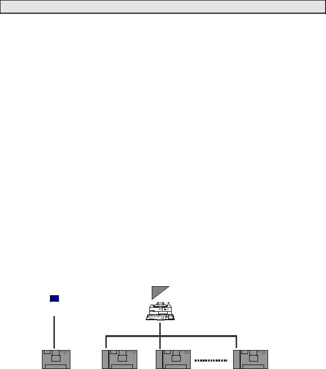
1.6 Programmer port function
The interface of the T1-16S’s programmer port is RS-232C. Normally this port is used to connect the programmer. However, this port can also be used for the computer link function.
The computer link is a data communication function between computer or operator interface unit and the T1-16S. The data in the T1-16S can be read and written by creating simple communication program on the computer. The computer link protocol of the T1-16S is published in “T1-16S User’s Manual− Communication Function − ”.
Item |
|
Specifications |
Interface |
Conforms to RS-232C |
|
Transmission system |
Half-duplex |
|
Synchronization |
Start-stop system (asynchronous) |
|
Transmission speed |
9600 bps (fixed) |
|
Transmission distance |
15 m max. |
|
Framing |
Start bit: |
1 bit |
|
Data bits: |
8 bits (fixed) |
|
Parity: |
Odd or none |
|
Stop bit: |
1 bit (fixed) |
Protocol |
T-series computer link (ASCII) |
|
|
Programmer (binary) |
|
Transmission delay option |
0 to 300 ms |
|
By using the multi-drop adapter (CU111), multiple T1-16Ss can be connected on an RS-485 line. The T-series PLC programming software (T-PDS) can also be used in this configuration.
Operator Interface |
Master Computer |
|||||||||
|
|
|
|
|
||||||
|
|
|
|
|
|
|
|
|
|
|
|
|
|
|
|
|
|
|
|
|
|
|
|
|
|
|
|
|
|
|
|
|
|
|
|
|
|
|
|
|
|
|
|
|
|
|
|
|
|
|
|
|
|
|
|
|
|
|
|
|
|
|
|
|
|
|
|
|
|
|
|
|
|
|
|
|
|
|
|
|
|
|
|
|
|
|
|
|
|
|
|
|
|
|
|
|
|
|
|
|
|
|
|
|
|
|
|
|
|
|
|
|
|
|
|
|
|
|
|
|
|
|
|
|
|
|
|
|
|
|
|
RS-232C
T1-16S |
|
RS-485 (1 km max.) |
Max. 32 T1-16Ss |
|
|
|
C |
C |
C |
U |
U |
U |
T1-16S |
T1-16S |
T1-16S |
Basic Hardware and Function 27
CTi Automation - Phone: 800.894.0412 - Fax: 208.368.0415 - Web: www.ctiautomation.net - Email: info@ctiautomation.net

6F3B0253
1. System Configuration
1.7 RS-485 port communication function
The T1-16S enhanced model has an RS-485 multi-purpose communication port. This port can work independent of the programmer port.
By using this communication port, one of the following four communication modes is available, computer link mode, data link mode, free ASCII mode, and Inverter connection mode.
For details of these functions, refer to the separate manual “T1-16S User’s Manual− Communication Function − ”.
Item |
Computer |
|
Free ASCII |
Inverter |
Data link |
|
link |
|
|
connection |
|
Interface |
Conforms to |
RS-458 |
|
|
|
Transmission system |
Half-duplex |
|
|
|
|
Synchronization |
Start-stop system (asynchronous) |
|
|||
Transmission code |
ASCII/binary |
ASCII |
Binary |
Binary |
|
Transmission speed |
300, 600, 1200, 2400, 4800, 9600, or |
19200 bps |
|||
|
19200 bps |
|
|
|
(fixed) |
Transmission |
1 km max. |
|
|
|
|
distance |
|
|
|
|
|
Framing |
Start bit: |
1 bit |
|
Special |
|
|
Data bits: 7 or 8 bits |
|
|
||
|
Parity: |
Odd, even, or none |
|
||
|
Stop bit: |
1 or 2 bits |
|
|
|
Protocol |
T-series |
|
User |
Inverter VF- |
Special |
|
computer |
|
defined |
A7/G7/S9 |
|
|
link (ASCII), |
ASCII |
binary |
|
|
|
Programmer |
messages |
protocol |
|
|
|
(binary) |
|
|
|
|
Link configuration |
1-to-N |
|
N/A |
1-to-N |
1-to-1 |
NOTE
T1-16S standard model does not have the RS-485 interface.
28 T1-16S User’s Manual
CTi Automation - Phone: 800.894.0412 - Fax: 208.368.0415 - Web: www.ctiautomation.net - Email: info@ctiautomation.net
 Loading...