


 Loading...
Toshiba Personal Computer
Satellite L600/L640/L645, Satellite Pro L600/Pro
L640/Pro L645
Maintenance Manual
TOSHIBA CORPORATION
File Number 960-Q08
Satellite L600/L640/L645, Satellite Pro L600/Pro L640/Pro L645Maintenance Manual (960-Q08)

Copyright
© 2010 by Toshiba Corporation. All rights reserved. Under the copyright laws, this manual cannot be reproduced in any form without the prior written permission of Toshiba. No patent liability is assumed with respect to the use of the information contained herein.
Toshiba Personal Computer Satellite L600/L640/L645, Satellite Pro L600/Pro L640/Pro L645 Maintenance Manual
First edition March.2010
Disclaimer
The information presented in this manual has been reviewed and validated for accuracy. The included set of instructions and descriptions are accurate for the Satellite L600/L640/L645, Satellite Pro L600/Pro L640/Pro L645 Series at the time of this manual's production. However, succeeding computers and manuals are subject to change without notice. Therefore, Toshiba assumes no liability for damages incurred directly or indirectly from errors, omissions, or discrepancies between any succeeding product and this manual.
Trademarks
Intel, Core2, Pentium, and Celeron are trademarks or registered trademarks of Intel Corporation or its subsidiaries in the United States and other countries/regions. Windows and Microsoft are registered trademarks of Microsoft Corporation.
Other trademarks and registered trademarks not listed above may be used in this manual.
Satellite L600/L640/L645, Satellite Pro L600/Pro L640/Pro L645Maintenance Manual (960-Q08)
Preface
This maintenance manual describes how to perform hardware service maintenance for the Toshiba Personal Computer Satellite L600/L640/L645, Satellite Pro L600/Pro L640/Pro L645 Series.
The procedures described in this manual are intended to help service technicians isolate faulty Field Replaceable Units (FRUs) and replace them in the field.
SAFETY PRECAUTIONS
Four types of messages are used in this manual to bring important information to your attention. Each of these messages will be italicized and identified as shown below.
DANGER: “Danger” indicates the existence of a hazard that could result in death or serious bodily injury, if the safety instruction is not observed.
WARNING: “Warning” indicates the existence of a hazard that could result in bodily injury, if the safety instruction is not observed.
CAUTION: “Caution” indicates the existence of a hazard that could result in property damage, if the safety instruction is not observed.
NOTE: “Note” contains general information that relates to your safe maintenance service.
Improper repair of the computer may result in safety hazards. Toshiba requires service technicians and authorized dealers or service providers to ensure the following safety precautions are adhered to strictly.
Be sure to fasten screws securely with the right screwdriver. If a screw is not fully fastened, it could come loose, creating a danger of a short circuit, which could cause overheating, smoke or fire.
If you replace the battery pack or RTC battery, be sure to use only the same model battery or an equivalent battery recommended by Toshiba. Installation of the wrong battery can cause the battery to explode.
Satellite L600/L640/L645, Satellite Pro L600/Pro L640/Pro L645Maintenance Manual (960-Q08)

The manual is divided into the following parts:
Chapter 1 Hardware Overview describes the Satellite L600/L640/L645, Satellite Pro L600/Pro L640/Pro L645 system unit and each FRU.
Chapter 2 Troubleshooting Procedures explains how to diagnose and resolve FRU problems.
Chapter 3 Test and Diagnostics describes how to perform test and diagnostic operations for maintenance service.
Chapter 4 Replacement Procedures describes the removal and replacement of the FRUs.
Appendices The appendices describe the following:
Handling the LCD Module
Board layout
Pin assignments
Keyboard scan/character code
Key layout
Wiring diagrams
Satellite L600/L640/L645, Satellite Pro L600/Pro L640/Pro L645Maintenance Manual (960-Q08)

Conventions
This manual uses the following formats to describe, identify, and highlight terms and operating procedures.
Acronyms
On the first appearance and whenever necessary for clarification acronyms are enclosed in parentheses following their definition. For example:
Read Only Memory (ROM)
Keys
Keys are used in the text to describe many operations. The key top symbol as it appears on the keyboard is printed in boldface type.
Key operation
Some operations require you to simultaneously use two or more keys. We identify such operations by the key top symbols separated by a plus (+) sign. For example, Ctrl + Pause (Break) means you must hold down Ctrl and at the same time press Pause (Break). If three keys are used, hold down the first two and at the same time press the third.
User input
Text that you are instructed to type in is shown in the boldface type below:
DISKCOPY A: B:
The display
Text generated by the computer that appears on its display is presented in the typeface below:
Format complete
System transferred
Satellite L600/L640/L645, Satellite Pro L600/Pro L640/Pro L645Maintenance Manual (960-Q08)

Table of Contents |
|
|
Chapter 1 Hardware Overview |
|
|
1.1 |
Features.......................................................................................................................... |
1 |
1.2 |
System Block Diagram .................................................................................................. |
6 |
1.3 |
2.5-inch Hard Disk Drive............................................................................................. |
10 |
1.4 |
Keyboard...................................................................................................................... |
13 |
1.5 |
TFT Color Display....................................................................................................... |
14 |
1.6 |
Power Rails .................................................................................................................. |
16 |
1.7 |
Batteries ....................................................................................................................... |
17 |
1.8 |
AC Adapter .................................................................................................................. |
20 |
1.9 |
ODD ............................................................................................................................. |
21 |
Satellite L600/L640/L645, Satellite Pro L600/Pro L640/Pro L645Maintenance Manual (960-Q08)

Chapter 2 Troubleshooting Procedures |
|
||
2.1 |
Troubleshooting |
............................................................................................................ |
1 |
2.2 |
Troubleshooting ...........................................................................................Flowchart |
2 |
|
2.3 |
Power Supply Troubleshooting..................................................................................... |
6 |
|
|
Procedure 1 .................................................................. |
Power Status Check |
6 |
|
Procedure 2 ..................................................................... |
Connection Check |
8 |
|
Procedure 3 ........................................................................ |
Charging Check |
8 |
|
Procedure 4 ................................................................ |
Replacement Check |
10 |
2.4 |
System Board Troubleshooting................................................................................... |
11 |
|
|
Procedure 1 ....................................................................... |
Message Check |
12 |
|
Procedure 2 ............................ |
Diagnostic Test Program Execution Check |
13 |
|
Procedure 3 ................................................................ |
Replacement Check |
13 |
2.5 |
SATA HDD/SSD .............................................................................Troubleshooting |
14 |
|
|
Procedure 1 ........................................................................ |
Partition Check |
14 |
|
Procedure 2 ....................................................................... |
Message Check |
15 |
|
Procedure 3 .......................................................................... |
Format Check |
16 |
|
Procedure 4 ............................ |
Diagnostic Test Program Execution Check |
17 |
|
Procedure 5 ............................. |
Connector Check and Replacement Check |
18 |
2.6 |
Keyboard Troubleshooting ......................................................................................... |
19 |
|
|
Procedure 1 ............................ |
Diagnostic Test Program Execution Check |
19 |
|
Procedure 2 ............................. |
Connector Check and Replacement Check |
20 |
2.7 |
Touch pad Troubleshooting ........................................................................................ |
21 |
|
|
Procedure 1 ............................ |
Diagnostic Test Program Execution Check |
21 |
|
Procedure 2 ............................. |
Connector Check and Replacement Check |
22 |
Satellite L600/L640/L645, Satellite Pro L600/Pro L640/Pro L645Maintenance Manual (960-Q08)

2.8 |
Display Troubleshooting.............................................................................................. |
23 |
|
|
Procedure 1 |
External Monitor Check........................................................... |
23 |
|
Procedure 2 |
Diagnostic Test Program Execution Check ............................. |
23 |
|
Procedure 3 |
Connector and Cable Check .................................................... |
24 |
|
Procedure 4 |
Replacement Check ................................................................. |
25 |
2.9 |
LAN Troubleshooting |
.................................................................................................. |
26 |
|
Procedure 1 |
Diagnostic Test Program Execution Check ............................. |
26 |
|
Procedure 2 |
Connector Check and Replacement Check.............................. |
26 |
2.10 |
Wireless LAN Troubleshooting................................................................................... |
27 |
|
|
Procedure 1 |
Transmitting-Receiving Check ................................................ |
27 |
|
Procedure 2 |
Antennas' Connection Check ................................................... |
28 |
|
Procedure 3 |
Replacement Check ................................................................. |
29 |
2.11 |
Sound Troubleshooting................................................................................................ |
30 |
|
|
Procedure 1 |
Connector Check...................................................................... |
30 |
|
Procedure 2 |
Replacement Check ................................................................. |
31 |
2.12 |
Bluetooth Troubleshooting .......................................................................................... |
32 |
|
|
Procedure 1 |
Connector Check and Replacement Check............................. |
32 |
2.13 |
HDMI Troubleshooting ............................................................................................... |
33 |
|
|
Procedure 1 |
Connector Check and Replacement Check............................. |
33 |
|
Procedure 2 |
External Monitor Check……………………………………...33 |
|
|
Procedure 3 |
Connector and Cable Check…………………………………34 |
|
|
Procedure 4 |
Replacement Check………………………………………….35 |
|
2.14 |
Memory Troubleshooting ............................................................................................ |
36 |
|
|
Procedure 1 |
Diagnostic Test Program Execution Check ............................. |
36 |
|
Procedure 2 |
Connect Check and Replacement Check…………………….36 |
|
2.15 |
3G Troubleshooting ..................................................................................................... |
|
37 |
|
Procedure 1 |
Connector Check and Replacement Check............................. |
37 |
2.16 |
Camera Troubleshooting.............................................................................................. |
38 |
|
|
Procedure 1 |
Camera Execution Check......................................................... |
38 |
|
Procedure 2 |
Connect Check and Replacement Check…………………….38 |
|
2.17 |
Microphone Troubleshooting ...................................................................................... |
39 |
|
Satellite L600/L640/L645, Satellite Pro L600/Pro L640/Pro L645Maintenance Manual (960-Q08)

|
Procedure 1 |
Sound Recorder Execution Check .......................................... |
39 |
|
Procedure 2 |
Connect Check and Replacement Check…………………….39 |
|
2.18 |
CRT Troubleshooting |
................................................................................................. |
40 |
|
Procedure 1 |
External Monitor Check.......................................................... |
40 |
|
Procedure 2 |
Connector and Cable Check………………………………….40 |
|
2.19 |
USB Troubleshooting |
................................................................................................. |
41 |
|
Procedure 1 |
Diagnostic Test Program Execution Check ............................ |
41 |
|
Procedure 2 |
Connect Check and Replacement Check…………………….41 |
|
2.20 |
LED Troubleshooting |
................................................................................................. |
42 |
|
Procedure 1 |
Each function Execution Check.............................................. |
42 |
|
Procedure 2 |
Connect Check and Replacement Check……………………42 |
|
2.21 |
Optical Disk Drive Troubleshooting........................................................................... |
43 |
|
|
Procedure 1 |
Diagnostic Test Program Execution Check ............................ |
43 |
|
Procedure 2 |
Connect Check and Replacement Check…………………….43 |
|
2.22 |
Modem Troubleshooting............................................................................................. |
44 |
|
|
Procedure 1 |
Diagnostic Test Program Execution Check ............................ |
44 |
|
Procedure 2 |
Connect Check and Replacement Check……………….……44 |
|
2.23 |
3 in 1 Card Reader Troubleshooting........................................................................... |
46 |
|
|
Procedure 1 |
Media Card Check .................................................................. |
46 |
|
Procedure 2 |
Connector Check and Replacement Check……………….….46 |
|
Satellite L600/L640/L645, Satellite Pro L600/Pro L640/Pro L645Maintenance Manual (960-Q08)

Chapter 3 Diagnostic Programs |
|
|
3.1 |
Tests and Diagnostics Software Overview |
....................................................................2 |
3.2 |
Executing the Diagnostic Test ....................................................................................... |
3 |
3.3 |
Subtest names................................................................................................................. |
7 |
3.4 |
System Test.................................................................................................................. |
10 |
3.5 |
Memory Test................................................................................................................ |
17 |
3.6 |
Keyboard Test.............................................................................................................. |
21 |
3.7 |
Display Test ................................................................................................................. |
24 |
3.8 |
Hard Disk Test ............................................................................................................. |
39 |
3.9 |
Real Time Clock Test .................................................................................................. |
42 |
3.10 |
Cache Memory Test..................................................................................................... |
44 |
3.11 |
High Resolution Display Test...................................................................................... |
46 |
3.12 |
Multimedia Test........................................................................................................... |
52 |
3.13 |
MEMORY2 Test.......................................................................................................... |
53 |
3.14 |
Error Codes and Error Status Names........................................................................... |
55 |
3.15 |
Running Test................................................................................................................ |
57 |
3.16 |
DMI INFOEMATION................................................................................................. |
58 |
3.17 |
Log Utilities ................................................................................................................. |
60 |
3.18 |
System Configuration .................................................................................................. |
62 |
3.19 |
Running Test Edit Item................................................................................................ |
63 |
3.20 |
Common Tests and Operation ..................................................................................... |
65 |
Satellite L600/L640/L645, Satellite Pro L600/Pro L640/Pro L645Maintenance Manual (960-Q08)
Chapter 4 Replacement Procedures |
|
|
4.1 |
Overview....................................................................................................................... |
1 |
|
Safety Precautions................................................................................................... |
2 |
|
Before You Begin ................................................................................................... |
3 |
|
Disassembly Procedure........................................................................................... |
4 |
|
Assembly Procedure ............................................................................................... |
5 |
|
Tools and Equipment .............................................................................................. |
5 |
|
Screw Tightening Torque ....................................................................................... |
6 |
|
Grip Color ............................................................................................................... |
6 |
|
Screw Notation........................................................................................................ |
7 |
4.2 |
Battery pack .................................................................................................................. |
8 |
4.3 |
HDD............................................................................................................................ |
11 |
4.4 |
Memory Module ......................................................................................................... |
14 |
4.5 |
Keyboard..................................................................................................................... |
17 |
4.6 |
Wireless LAN card and BT Module ........................................................................... |
20 |
4.7 |
3G Module .................................................................................................................. |
23 |
4.8 |
Display Assembly ....................................................................................................... |
26 |
4.9 |
Top Cover Assembly .................................................................................................. |
33 |
4.10 |
Touch pad.................................................................................................................... |
36 |
4.11 |
I/O board ..................................................................................................................... |
39 |
4.12 |
System Board .............................................................................................................. |
41 |
4.13 |
CPU Heat Sink............................................................................................................ |
46 |
4.14 |
LCD unit ..................................................................................................................... |
48 |
4.15 |
Web Camera Module .................................................................................................. |
52 |
4.16Application for Thermal pad and grease on CPU, NB, V-ram and chock…………...55
4.17Speaker Box………………………………………………………………………….57
4.18ODD Bezel…………………………………………………………………………...60
Satellite L600/L640/L645, Satellite Pro L600/Pro L640/Pro L645Maintenance Manual (960-Q08)

Appendices |
|
|
Appendix A |
Handling the LCD Module ................................................................................ |
1 |
Appendix B |
Board Layout ..................................................................................................... |
1 |
Appendix C |
Pin Assignments................................................................................................. |
1 |
Appendix D |
Keyboard Scan/Character Codes ....................................................................... |
1 |
Appendix E |
Key Layout......................................................................................................... |
1 |
Appendix F |
Wiring Diagrams................................................................................................ |
1 |
Satellite L600/L640/L645, Satellite Pro L600/Pro L640/Pro L645Maintenance Manual (960-Q08)

Chapter 1 Hardware Overview
Chapter 1
Hardware Overview
Satellite L600/L640/L645, Satellite Pro L600/Pro L640/Pro L645 Maintenance Manual (960-Q08)

Chapter 1 Hardware Overview |
|
||
Chapter 1 |
Contents |
|
|
1.1 |
Features......................................................................................................................... |
|
1 |
1.2 |
System Block Diagram ................................................................................................. |
6 |
|
1.3 |
2.5-inch Hard Disk Drive............................................................................................ |
10 |
|
1.4 |
Keyboard..................................................................................................................... |
|
13 |
1.5 |
TFT Color Display...................................................................................................... |
14 |
|
1.6 |
Power Rails ................................................................................................................. |
|
16 |
1.7 |
Batteries ...................................................................................................................... |
|
17 |
1.8 |
AC Adapter ................................................................................................................. |
|
20 |
1.9 |
ODD ............................................................................................................................ |
|
21 |
Satellite L600/L640/L645, Satellite Pro L600/Pro L640/Pro L645 Maintenance Manual (960-Q08)

Chapter 1 Hardware Overview |
|
|
Figures |
|
|
Figure 1-1-1 Left of the computer.......................................................................................... |
4 |
|
Figure 1-1-2 Right of the computer ....................................................................................... |
5 |
|
Figure 1-2-1 System block diagram for Intel Platform.......................................................... |
7 |
|
Figure 1-3-1 2.5-inch Hard Disk Drive................................................................................ |
10 |
|
Figure 1-4-1 |
Keyboard for US Style.................................................................................... |
13 |
Figure 1-5-1 |
AUO LCD Function Block Diagram…………………………………………14 |
|
Figure 1-9-1 |
DVD super multi drive………………………………………………………21 |
|
Tables |
|
|
Table 1-3-2 2.5-inch HDD dimensions .............................................................................. |
11 |
|
Table 1-3-3 2.5-inch HDD specifications........................................................................... |
12 |
|
Table 1-5-2 LCD module specifications............................................................................. |
14 |
|
Table 1-6-1 Calpella Power supply output rating............................................................... |
16 |
|
Table 1-7-1 |
Battery specifications...................................................................................... |
17 |
Table 1-7-2 Time required for charges of main battery ..................................................... |
18 |
|
Table 1-7-3 Data preservation time .................................................................................... |
18 |
|
Table 1-7-4 Time required for charge of RTC battery ....................................................... |
19 |
|
Table 1-8-1 AC adapter specifications .............................................................................. |
20 |
|
Table 1-9-2 DVD Super Multi Drive Outline Dimensions................................................ |
21 |
|
Table 1-9-3 DVD super multi drive specification ............................................................. |
23 |
|
Table 1-9-4 |
Blue ray ODD dimensions ............................................................................. |
24 |
Table 1-9-5 |
Blue ray ODD specifications ......................................................................... |
25 |
Satellite L600/L640/L645, Satellite Pro L600/Pro L640/Pro L645 Maintenance Manual (960-Q08)

Chapter 1 Hardware Overview
Features
1.1 Features
The Satellite L600/L640/L645, Satellite Pro L600/Pro L640/Pro L645 (Intel Platform) features are listed below.
Microprocessor
Microprocessor that is used will be different by the model. It supports processors as follows:
-Intel ○R Core i7-620M
-Intel ○R Core i5-430M/450M/520M/540M
-Intel ○R Core i3-330M/ 350M/370M
-Intel ○R Pentium P6000/ P6100
-Intel ○R Celeron P4500
Memory
Two DDR3 SO-DIMM (DDR3-1066 or compatible) used and be up to 8GB which can be upgraded through Memory Module Slot. Maximum upgradeable system memory may depend on the model
VRAM
-Shared with System RAM for Intel HM55 UMA SKU
-Discreet VRAM Memory that is used will be different by the model,
which support as:
512MB, 1GB, 2GB
HDD
5400rpm: 250GB, 320GB, 400GB, 500GB, 640GB internal drives. 2.5 inch x 9.5mm height.
Satellite L600/L640/L645, Satellite Pro L600/Pro L640/Pro L645 Maintenance Manual (960-Q08)

Chapter 1 Hardware Overview
SSD
64GB, 128GB, 256GB, 512GB. 2.5 inch x 9.5mm height.
ODD
12.7mm integrated ODD
Support: DVD Super Multi (+-R Double Layer) & Blue Ray ODD.
Display LCD
14.1-inch, 1366x768(16:9), LED-backlight. External monitor
Supported via RGB and HDMI connectors.
Keyboard
Keyboard module has 88-89 keys. It supports Windows key and Application key.
Camera
CMOS,0.3M,VGA/CMOS,1.3M,SXGA/0.3M,VGA/1.3M,SXGA/CMOS,0.3M/CMO
S,1.3M
Microphone Ext. MIC port
Headphones Line out Jack Earphone port
Satellite L600/L640/L645, Satellite Pro L600/Pro L640/Pro L645 Maintenance Manual (960-Q08)

Chapter 1 Hardware Overview
Modem
Connectors for Modem is separately mounted
Battery
The RTC battery is equipped inside the computer. The main battery is a detachable lithium ion battery.
-3 cell 10.8V/2250mAhr
-6 cell 10.8V/4400mAhr/4500mAhr/5600mAhr
-12cell 10.8V/9000mAhr
USB (Universal Serial Bus)
2 standard USB ports and 1 integrated in E-SATA connector USB port are provided. The ports comply with the USB2.0 standard.
Sound system
Internal stereo speaker, Internal MIC (Option), external monaural microphone connector, stereo headphone connector. The computer will support Dolby to decrease noise.
Wireless LAN
Some computers in this series are equipped with a Wireless LAN card. There are two types: WLAN combo Wimax module and WLAN combo + BT combo module.
LAN
The computer has built-in support for Ethernet LAN (10 megabits per second, 10BASE-T), Fast Ethernet LAN (100 megabits per second, 100 BASE-TX) and Extra Ethernet LAN (1000 megabits per second, 1000 BASE-TX) (Option)
Bridge Media Slot
SD/MS/MS pro/MMC are supported.
Satellite L600/L640/L645, Satellite Pro L600/Pro L640/Pro L645 Maintenance Manual (960-Q08)

Chapter 1 Hardware Overview
Bluetooth
Some computers in this series offer Bluetooth wireless communication functionality with Broadcom 802.11(b/g/n) BCM94313-HMC w/ BT V3.0+HS Combo module.
3G
Support TD-SCDMA, W-CDMA
Security Kensington Lock,
Hard Disk Drive Password
Satellite L600/L640/L645, Satellite Pro L600/Pro L640/Pro L645 Maintenance Manual (960-Q08)
Chapter 1 Hardware Overview
16
 15
15
14 13
17
|
|
|
13 |
|
|
|
|
|
|
12 |
|
|
|
|
|
|
|
|
|
11 |
|
|
1 |
2 |
|
|
|
|
|
|
|
|
|
|
|
|
|
|
|
|
|
||
|
|
3 |
4 |
|
|
|
|
|
18 |
|
|
|
5 |
6 |
7 |
8 |
9 |
10 |
|
||
|
|
|
|
|
||||||
|
|
|
|
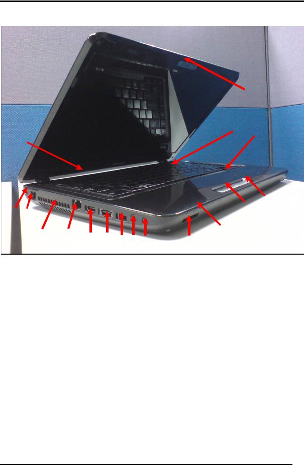
Figure 1-1-1 left of the computer |
|
|||||
1. |
Security Lock Hole |
|
|
13. Touch Pad |
|
|
||||
2. |
RJ11 Port |
|
|
|
14. Keyboard |
|
|
|||
3. FAN Hole |
|
|
|
15. LCD Panel |
|
|
||||
4. |
RL45 Port |
|
|
|
16. Web camera |
|
|
|||
5. |
HDMI Port |
|
|
|
17. Power Button |
|
|
|||
6. |
E-SATA Port (integrated a USB Port) |
|
|
|
||||||
7. |
USB Port |
|
|
|
18. Hall-sensor |
|
|
|||
8.Ext. MIC Port
9.Earphone Port
10.Card Reader Port
11.Touch Pad Control Left Button
12.Touch Pad Control Right Button
Satellite L600/L640/L645, Satellite Pro L600/Pro L640/Pro L645 Maintenance Manual (960-Q08)
Chapter 1 Hardware Overview
18
21 20 19
22
Figure 1-1-2 right of the computer
18.Speaker
19.DC-IN Jack
20.CRT Port
21.USB Port
22.ODD
Satellite L600/L640/L645, Satellite Pro L600/Pro L640/Pro L645 Maintenance Manual (960-Q08)

Chapter 1 Hardware Overview
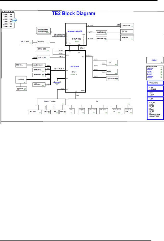
1.2 System Block Diagram
Figure 1-2-1 shows the system block diagram.
Satellite L600/L640/L645, Satellite Pro L600/Pro L640/Pro L645 Maintenance Manual (960-Q08)
Chapter 1 Hardware Overview
Figure 1-1-1 System block diagram for Intel Platform
Satellite L600/L640/L645, Satellite Pro L600/Pro L640/Pro L645 Maintenance Manual (960-Q08)

Chapter 1 Hardware Overview
The PC contains the following components.
CPU
-Intel ○R Core i7-620M
-Intel ○R Core i5-430M/450M/520M/540M
-Intel ○R Core i3-330M/ 350M/370M
-Intel ○R Pentium P6000/ P6100
-Intel ○R Celeron P4500
Memory
Two memory slots capable of accepting DDR3-SDRAM 512MB, 1GB, 2GB, 4GB memory modules for a maximum of 8GB.
208-pin SO-DIMM
1.5V operation voltage
ME+BIOS ROM (Flash memory)
32Mbit
EC ROM (Flash memory)
4Mbit
Chipset
IBEX PEAK-M (Intel PCH HM55, HM57 design ready)
Supports FDI BUS for video out
Supports PCI-E Gen2 (version 2.0)
-- 1071 FCBGA package, 24.6mmx26.5mm
Satellite L600/L640/L645, Satellite Pro L600/Pro L640/Pro L645 Maintenance Manual (960-Q08)

Chapter 1 Hardware Overview
VGA Card
AMD-ATI (Madison-LP, Park-XT, M92XTX)
Supports ATI HyperMemory*
Supports PCI-E Gen2 (version 2.0)
Other main system chips
• Clock Generator (Congo Platform: SLG8SP595VTR)
EC (WO/CIR WPCE775CA0DG)
HD Audio (CONEXANT CX20583-10Z)
Card Reader controller (REALTEAK RTS5159) 10/100 LAN controller (Atheros AR8152M) 10/100/1000 LAN controller (Atheros AR8151M)
Mini Card
Wireless LAN (BTO) IEEE802.11b/g or IEEE802.11b/g/n
3G communication (option) TD-SCDMA, WCDMA
Wireless WAN (BTO)
HSPA
Bluetooth
Bluetooth V2.1+EDR and Combo module. (BTO)
Satellite L600/L640/L645, Satellite Pro L600/Pro L640/Pro L645 Maintenance Manual (960-Q08)
Chapter 1 Hardware Overview
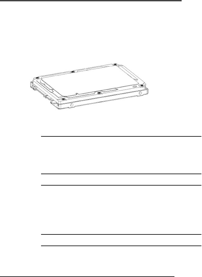
1.3 2.5-inch Hard Disk Drive
A compact, high-capacity HDD is with a height of 9.5mm and contains a 2.5-inch magnetic disk and magnetic heads.
Figure 1-3-1 shows a view of the 2.5-inch HDD and Tables 1-3-2 and 1-3-3 list the specifications.
Figure 1-3-1 2.5-inch HDD
Parameter |
|
Standard value |
|
|
||
|
|
|
|
|
||
Toshiba |
Toshiba |
Toshiba |
Toshiba |
Toshiba |
||
|
|
MK1665GSX |
MK2565GSX |
MK3265GSX |
MK5065GSX |
MK6465GSX |
|
|
|
|
|
|
|
Outline |
Width |
|
69.85 +/- 0.25 |
|
|
|
(mm) |
|
|
|
|||
|
|
|
|
|
|
|
|
|
|
|
|
|
|
dimensions |
Height |
|
|
9.5 |
|
|
(mm) |
|
|
|
|
||
|
|
|
|
|
|
|
Depth (mm) |
|
100.2 +/- 0.25 |
|
|
||
|
|
|
|
|
||
|
|
|
|
|
|
|
Weight (g) |
97/98 |
97/98 |
97/98 |
101/102 |
101/102 |
|
|
|
|
Standard value |
|
|
|
Parameter |
|
|
|
|
||
HITACHI |
HITACHI |
HITACHI |
HITACHI |
|||
|
|
HTS545016B9A300 |
HTS545025B9A300 |
HTS545032B9A300 |
HTS545050B9A300 |
|
|
|
|
|
|
|
|
Outline |
Width |
|
69.85 +/- 0.25 |
|
|
|
(mm) |
|
|
|
|||
|
|
|
|
|
|
|
|
|
|
|
|
|
|
dimensions |
Height |
|
|
9.5 |
|
|
(mm) |
|
|
|
|
||
|
|
|
|
|
|
|
Depth (mm) |
|
100.2 +/- 0.25 |
|
|
||
Weight (g) |
95(Max) |
95(Max) |
102(Max) |
102(Max) |
||
|
|
|
|
|
|
|
Satellite L600/L640/L645, Satellite Pro L600/Pro L640/Pro L645 Maintenance Manual (960-Q08)

Chapter 1 Hardware Overview
Parameter |
|
|
|
Standard value |
|
|
|
|
|
||||||||
|
|
|
|
|
|
|
|
|
|
|
|
|
|||||
|
WD1600BEVT |
WD2500BEVT |
WD3200BEVT |
WD6400BEVT |
WD5000BEVT |
|
|||||||||||
|
|
|
|
|
|
|
|||||||||||
|
|
|
|
|
|
|
|
|
|
|
|
|
|
|
|
|
|
Outline |
|
Width |
|
|
69.85 +/- 0.25 |
|
|
|
|
|
|
||||||
|
(mm) |
|
|
|
|
|
|
|
|
||||||||
|
|
|
|
|
|
|
|
|
|
|
|
|
|
|
|||
|
|
|
|
|
|
|
|
|
|
|
|
|
|
|
|
|
|
dimensions |
|
Height |
|
|
|
|
|
9.5 |
|
|
|
|
|
|
|||
|
(mm) |
|
|
|
|
|
|
|
|
|
|
|
|||||
|
|
|
|
|
|
|
|
|
|
|
|
|
|
|
|||
Depth (mm) |
|
|
100.2 +/- 0.25 |
|
|
|
|
|
|
||||||||
|
|
|
|
|
|
|
|
|
|
|
|
|
|
|
|||
Weight (g) |
|
97/98 |
97/98 |
|
97/98 |
|
97/98 |
|
97/98 |
|
|
||||||
|
|
|
|
|
|
|
|
|
|
|
|
|
|
|
|
|
|
Parameter |
|
|
|
|
Standard value |
|
|
|
|
|
|
||||||
|
|
|
|
|
|
|
|
|
|
|
|
|
|||||
|
ST9160314AS |
ST9250315AS |
ST9320325AS |
|
ST9500325AS |
|
|
||||||||||
|
|
|
|
|
|
|
|
|
|||||||||
|
|
|
|
|
|
|
|
|
|
|
|
|
|
|
|
|
|
Outline |
|
Width |
|
|
69.85 +/- 0.25 |
|
|
|
|
|
|
||||||
|
(mm) |
|
|
|
|
|
|
|
|
||||||||
|
|
|
|
|
|
|
|
|
|
|
|
|
|
|
|||
|
|
|
|
|
|
|
|
|
|
|
|
|
|
|
|
|
|
dimensions |
|
Height |
|
|
|
|
|
9.5+/-0.2 |
|
|
|
|
|
|
|||
|
(mm) |
|
|
|
|
|
|
|
|
|
|
|
|||||
|
|
|
|
|
|
|
|
|
|
|
|
|
|
|
|||
Depth (mm) |
|
|
100.35 +/- 0.25 |
|
|
|
|
|
|
||||||||
|
|
|
|
|
|
|
|
|
|
|
|
|
|
|
|||
Weight (g) |
|
93.5 |
93.5 |
|
98.8 |
|
|
98.8 |
|
|
|||||||
|
|
|
|
|
|
|
|
|
|
|
|
|
|
|
|
|
|
|
|
|
|
|
|
Table 1-3-2 2.5-inch HDD dimensions |
|
|
|
|
|
||||||
|
|
|
|
|
|
|
|
|
|
Specification |
|
|
|
|
|
||
Parameter |
|
|
|
|
|
|
|
|
|
|
|
|
|||||
|
|
Toshiba |
|
Toshiba |
|
Toshiba |
Toshiba |
Toshiba |
|||||||||
|
|
|
|
|
|
MK1665GSX |
|
MK2565GSX |
|
MK3265GSX |
MK5065GSX |
MK6465GSX |
|||||
Storage size |
|
|
|
160G |
|
250G |
|
320G |
|
500G |
640G |
||||||
(formatted) |
|
|
|
|
|
|
|
|
|||||||||
|
|
|
|
|
|
|
|
|
5,400 |
|
|
|
|
|
|
||
Speed (RPM) |
|
|
|
|
|
|
|
|
|
|
|
|
|
|
|
||
|
|
|
|
|
|
464~1164 typical/3GBytes |
|
|
|
|
|||||||
Data transfer Rate |
|
|
|
|
|
|
|
|
|||||||||
-To/From Media
-T0/From Host
bus |
transfer |
rate |
|
|
3Gbps |
|
||
(MB/s) |
|
|
|
|
|
|||
|
|
|
|
12 |
|
|
||
Average random |
|
|
|
|
||||
seek |
|
|
|
|
|
|
|
|
time(read)(ms) |
|
|
|
3.5(type)/9.5(max) |
|
|||
Power-on-to- |
|
|
|
|
||||
ready (sec) |
|
|
|
|
|
|
|
|
|
|
|
|
|
Specification |
|
||
|
Parameter |
|
|
HITACHI |
HITACHI |
HITACHI |
|
HITACHI HTS545050B9A300 |
|
|
|
|
HTS545016B9A300 |
HTS545025B9A300 |
HTS545032B9A300 |
|
|
|
|
|
|
|
|
|||
|
|
|
|
|
320G |
|
|
|
Storage size |
|
|
160G |
250G |
|
500G |
||
(formatted) |
|
|
|
|
|
|
||
|
|
|
|
5,400 |
|
|
||
Speed (RPM) |
|
|
|
|
|
|
||
Data transfer Rate |
|
|
|
|
|
|||
- To/From Media |
845/3GBytes |
|
875/3GBytes |
|
||||
- T0/From Host |
|
|
|
|
||||
|
|
|
|
|
|
|
||
|
|
|
|
|
|
|
|
|
bus |
transfer |
rate |
|
|
3Gbps |
|
||
(MB/s) |
|
|
|
|
|
|||
|
|
|
|
|
|
|
||
Satellite L600/L640/L645, Satellite Pro L600/Pro L640/Pro L645 Maintenance Manual (960-Q08)
Chapter 1 Hardware Overview
Average random |
|
12 |
|
|
|||||
seek |
|
|
|
|
|
|
|
||
time(read)(ms) |
|
|
|
|
|
|
|
|
|
Power-on-to- |
|
|
|
|
3.5 |
|
|
||
ready (sec) |
|
|
|
|
|
|
|||
|
|
|
|
|
|
|
|
||
Parameter |
|
|
|
|
Specification |
|
|
||
|
|
WD1600BEVT |
WD2500BEVT |
|
WD3200BEVT |
WD6400BEVT |
WD5000BEVT |
||
|
|
|
|
|
|||||
|
|
|
|
|
|
|
|
|
|
Storage size |
|
|
160G |
250G |
|
320G |
640G |
500G |
|
(formatted) |
|
|
|
||||||
|
|
|
|
|
5,400 |
|
|
||
Speed (RPM) |
|
|
|
|
|
|
|
||
Data transfer Rate |
|
|
|
|
|
|
|||
- To/From Media |
|
106/3GBytes |
|
|
|||||
- T0/From Host |
|
|
|
|
|
|
|||
|
|
|
|
|
|
|
|
||
|
|
|
|
|
|
|
|
|
|
bus |
transfer |
rate |
|
|
3Gbps |
|
|
||
(MB/s) |
|
|
|
|
|
|
|
||
|
|
|
|
|
|
|
|
||
Average random |
|
|
12 |
|
|
||||
seek |
|
|
|
|
|
|
|
||
time(read)(ms) |
|
|
|
|
|
|
|
|
|
Power-on-to- |
|
|
|
|
4.0 |
|
|
||
ready (sec) |
|
|
|
|
|
|
|||
|
|
|
|
|
|
|
|
||
Parameter |
|
|
|
|
Specification |
|
|
||
|
|
ST9160314AS |
ST9250315AS |
|
ST9320325AS |
ST9500325AS |
|||
|
|
|
|
|
|||||
|
|
|
|
|
|
|
|
|
|
Storage size |
|
|
160G |
250G |
|
320G |
500G |
||
(formatted) |
|
|
|
||||||
|
|
|
|
|
5,400 |
|
|
||
Speed (RPM) |
|
|
|
|
|
|
|
||
|
|
|
|
|
|
|
|||
Data transfer Rate |
|
|
|
|
|
||||
- To/From Media |
|
300/3GBytes |
|
|
|||||
- T0/From Host |
|
|
|
|
|
|
|
|
|
|
|
|
|
|
|
|
|
|
|
bus |
transfer |
rate |
|
|
3Gbps |
|
|
||
(MB/s) |
|
|
|
|
|
|
|
||
|
|
|
|
|
|
|
|
||
Average random |
|
|
14 |
|
|
||||
seek |
|
|
|
|
|
|
|
||
time(read)(ms) |
|
|
|
|
|
|
|
|
|
Power-on-to- |
|
|
|
3.6(typical)3.8(max) |
|
|
|||
ready (sec) |
|
|
|
|
|
||||
|
|
|
|
|
|
|
|
||
Table 1-3-3 2.5-inch HDD specifications
Satellite L600/L640/L645, Satellite Pro L600/Pro L640/Pro L645 Maintenance Manual (960-Q08)
Chapter 1 Hardware Overview
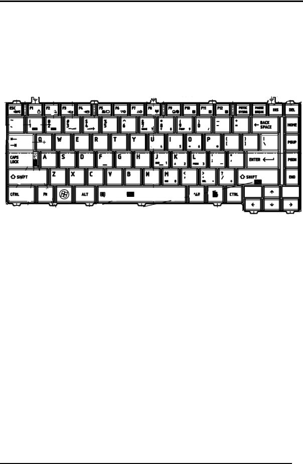
1.4 Keyboard
The Rostock 10G keyboard has two different kinds of placement, here is for US style for your reference.
Figure 1-4-1 is a view of the keyboard for US style
Figure 1-4-1 Keyboard for US style
See Appendix E for details of the keyboard layout
Satellite L600/L640/L645, Satellite Pro L600/Pro L640/Pro L645 Maintenance Manual (960-Q08)
Chapter 1 Hardware Overview
1.5 TFT Color Display
The Satellite L645, Satellite Pro L645 use LED to control backlight.
1.5.1 LCD Function Block
Figure 1-5-1 shows a view of the LCD Function Block and Table 1-5-2 lists the specifications.
Figure 1-5-1 AUO LCD Function Block Diagram
Item |
|
Specifications(WXGA+) |
|
||
|
|
|
|
||
AUO B140XW01 V6 |
LG Display |
Samsung |
CMO N140B6-L02 |
||
|
|||||
|
LP140WH1-TLA1 |
LTN140AT07-T01 |
|||
|
|
|
|||
Number |
1366x3(RGB) x 768 |
1366x3(RGB) x 768 |
1366x3(RGB) x 768 |
1366x3(RGB) x 768 |
|
of Dots |
|||||
|
|
|
|
||
Dot |
0.2148(H)X0.2148(V) |
0.2148(H)X0.2148(V) |
0.2148(H)X0.2148(V) |
0.2148(H)X0.2148(V) |
|
spacing |
|||||
(mm) |
|
|
|
|
|
Display |
6-bit, 262,144 colors |
6-bit, 262,144 colors |
6-bit, 262,144 colors |
6-bit, 262,144 colors |
|
Colors |
|||||
|
|
|
|
||
Table 1-5-2 LCD module specifications
Satellite L600/L640/L645, Satellite Pro L600/Pro L640/Pro L645 Maintenance Manual (960-Q08)
Loading...