


FILE NO. A03-013
SERVICE MANUAL
<OWNER’S MANUAL/INSTALLATION MANUAL>
SPLIT TYPE
RAV-SP1100UT-E RAV-SP560AT-E, RAV-SP800AT-E RAV-SP1100AT-E, RAV-SP1400AT-E
R410A
The type of all the indoor units described in this Service Manual is a new model, RAV-SP1100UT-E only. For the other indoor units to be combined, refer to the Service Manuals for the following models.
|
Indoor unit |
Service Manual No. |
|
|
|
|
|
|
RAV-SM560UT-E |
A02-013 |
|
|
|
|
|
4-way Air Discharge Cassette type |
RAV-SM800UT-E |
A02-013 |
|
|
RAV-SM1400UT-E |
A03-003 |
|
|
RAV-SM561BT-E |
A03-007 |
|
Concealed Duct type |
RAV-SM801BT-E |
A03-007 |
|
|
|
||
RAV-SM1101BT-E |
A03-007 |
||
|
|||
|
RAV-SM1401BT-E |
A03-007 |
|
|
RAV-SM561CT-E |
A03-015 |
|
Under Ceiling type |
RAV-SM801CT-E |
A03-015 |
|
|
|
||
RAV-SM1101CT-E |
A03-015 |
||
|
|||
|
RAV-SM1401CT-E |
A03-015 |
|
|
|
|
|
High wall type |
RAV-SM560KRT-E |
A02-013 |
|
RAV-SM800KRT-E |
A02-013 |
||
|
PRINTED IN JAPAN, Feb.,2004 ToMo

ADOPTION OF NEW REFRIGERANT
This Air Conditioner is a new type which adopts a new refrigerant HFC (R410A) instead of the conventional refrigerant R22 in order to prevent destruction of the ozone layer.
WARNING
Cleaning of the air filter and other parts of the air filter involves dangerous work in high places, so be sure to have a service person do it. Do not attempt it yourself. The cleaning diagram for the air filter is there for the service person, and not for the customer.
– 2 –

Indoor Unit (4-Way Air Discharge Cassette Type) ––––––––––––––––––––––––
RAV-SP1100UT-E |
|
OWNWE’S MANUAL |
|
ACCESSORIES (SOLD SEPARATELY) ............................... |
4 |
PRECAUTIONS FOR SAFETY ............................................ |
4 |
PARTS NAME ....................................................................... |
6 |
PARTS NAME OF REMOTE CONTROLLER ....................... |
7 |
CORRECT USAGE ............................................................... |
9 |
AUTOMATIC OPERATION (Auto Changeover) ................ |
10 |
ADJUSTMENT OF WIND DIRECTIONd ............................ |
11 |
TIMER OPERATION ........................................................... |
12 |
MAINTENANCE .................................................................. |
14 |
AIR CONDITIONER OPERATIONS AND PERFORMANCE ... |
15 |
RE-INSTALLATION ............................................................ |
16 |
TROUBLES AND CAUSES ................................................ |
16 |
INSTALLATION MANUAL
Accessory parts and Parts to be procured locally ........ |
18 |
5 |
|
1 |
PRECAUTIONS FOR SAFETY .................................... |
19 |
6 |
2 |
SELECTION OF INSTALLATION PLACE ................... |
21 |
7 |
3 |
DRAIN PIPING WORK ................................................. |
26 |
8 |
4 |
REFRIGERANT PIPING AND EVACUATING .............. |
28 |
|
ELECTRICAL WORK ................................................... |
30 |
TEST RUN ................................................................... |
33 |
TROUBLESHOOTING ................................................. |
34 |
MAINTENANCE ........................................................... |
35 |
Outdoor Unit –––––––––––––––––––––––––––––––––––––––––––––––––––––––––
RAV-SP560AT-E, RAV-SP800AT-E
INSTALLATION MANUAL
1 |
PRECAUTIONS FOR SAFETY .................................... |
36 |
5 |
2 |
ACCESSORY AND REFRIGERANT ........................... |
37 |
6 |
3 |
SELECTION OF INSTALLATION ................................ |
38 |
7 |
4 |
REFRIGERANT PIPING .............................................. |
43 |
|
EVACUATING ............................................................... |
45 |
ELECTRICAL WORK ................................................... |
47 |
FINAL INSTALLATION CHECKS ................................ |
48 |
RAV-SP1100AT-E, RAV-SP1400AT-E
INSTALLATION MANUAL
1 |
PRECAUTIONS FOR SAFETY .................................... |
50 |
5 |
2 |
ACCESSORY AND REFRIGERANT ........................... |
51 |
6 |
3 |
SELECTION OF INSTALLATION ................................ |
52 |
7 |
4 |
REFRIGERANT PIPING .............................................. |
56 |
|
EVACUATING ............................................................... |
58 |
ELECTRICAL WORK ................................................... |
60 |
FINAL INSTALLATION CHECKS ................................ |
61 |
Accessories ––––––––––––––––––––––––––––––––––––––––––––––––––––
OWNER’S MANUAL |
|
|
REMOTE CONTROLLER FOR AIR CONDITIONER (SPLIT TYPE) |
|
|
<Wireless Type> |
TCB-AX21U (W)-E .......................................... |
63 |
WEEKLY TIMER FOR AIR CONDITIONER (SPLIT TYPE) |
|
|
<Program Weekly Timer Type> |
RBC-EXW21E ................................................. |
72 |
REMOTE CONTROLLER FOR AIR CONDITIONER |
|
|
<Simple Operation Type> |
RBC-AS21E .................................................... |
78 |
INSTALLATION MANUAL |
|
|
Standard Remote Controller |
RBC-AMT21E ................................................. |
81 |
Simple Remote Controller |
RBC-AS21E .................................................... |
82 |
Program Weekly Timer |
RBC-EXW21E ................................................. |
83 |
Remote sensor |
TCB-TC21LE .................................................. |
84 |
Remote Controller Wireless Kit |
TCB-AX21U (W)-E .......................................... |
85 |
Network Adapter for Air Conditioner |
|
|
(Use for Indoor Unit Only) |
TCB-PCNT20E ............................................... |
86 |
RAV-SP1100UT-E
SP560AT-E |
SP800AT-E |
RAV- |
RAV- |
SP1100AT-E |
SP1400AT-E |
RAV- |
RAV- |
ACCESSORIES
1 PRECAUTIONS FOR SAFETY
•Ensure that all Local, National and International regulations are satisfied.
•Read this “PRECAUTIONS FOR SAFETY” carefully before Installation.
•The precautions described below include the important items regarding safety. Observe them without fail.
•After the installation work, perform a trial operation to check for any problem.
Follow the Owner’s Manual to explain how to use and maintain the unit to the customer.
•Turn off the main power supply switch (or breaker) before the unit maintenance.
•Ask the customer to keep the Installation Manual together with the Owner’s Manual.
CAUTION New Refrigerant Air Conditioner Installation
•THIS AIR CONDITIONER ADOPTS THE NEW HFC REFRIGERANT (R410A) WHICH DOES NOT DESTROY OZONE LAYER.
The characteristics of R410A refrigerant are ; easy to absorb water, oxidizing membrane or oil, and its pressure is approx. 1.6 times higher than that of refrigerant R22. Accompanied with the new refrigerant, refrigerating oil has also been changed. Therefore, during installation work, be sure that water, dust, former refrigerant, or refrigerating oil does not enter the refrigerating cycle.
To prevent charging an incorrect refrigerant and refrigerating oil, the sizes of connecting sections of charging port of the main unit and installation tools are charged from those for the conventional refrigerant. Accordingly the exclusive tools are required for the new refrigerant (R410A).
For connecting pipes, use new and clean piping designed for R410A, and please care so that water or dust does not enter. Moreover, do not use the existing piping because there are problems with pressure-resistance force and impurity in it.
CAUTION To Disconnect the Appliance from Main Power Supply.
This appliance must be connected to the main power supply by means of a switch with a contact separation of at least 3 mm.
The installation fuse (25A D type  ) must be used for the power supply line of this conditioner.
 WARNING
•Ask an authorized dealer or qualified installation professional to install/maintain the air conditioner.
Inappropriate installation may result in water leakage, electric shock or fire.
•Turn off the main power supply switch or breaker before attempting any electrical work.
Make sure all power switches are off. Failure to do so may cause electric shock.
•Connect the connecting cable correctly.
If the connecting cable is connected in a wrong way, electric parts may be damaged.
•When moving the air conditioner for the installation into another place, be very careful not to enter any gaseous matter other than the specified refrigerant into the refrigeration cycle.
If air or any other gas is mixed in the refrigerant, the gas pressure in the refrigeration cycle becomes abnormally high and it may resultingly causes pipe burst and injuries on persons.
•Do not modify this unit by removing any of the safety guards or by by-passing any of the safety interlock switches.
•Exposure of unit to water or other moisture before installation may cause short-circuit of electrical parts.
Do not store it in a wet basement or expose to rain or water.
•After unpacking the unit, examine it carefully if there are possible damage.
•Do not install in a place that might increase the vibration of the unit.
•To avoid personal injury (with sharp edges), be careful when handling parts.
•Perform installation work properly according to the Installation Manual.
Inappropriate installation may result in water leakage, electric shock or fire.
36
•When the air conditioner is installed in a small room, provide appropriate measures to ensure that the concentration of refrigerant leakage occur in the room does not exceed the critical level.
•Install the air conditioner securely in a location where the base can sustain the weight adequately.
•Perform the specified installation work to guard against an earthquake.
If the air conditioner is not installed appropriately, accidents may occur due to the falling unit.
•If refrigerant gas has leaked during the installation work, ventilate the room immediately.
If the leaked refrigerant gas comes in contact with fire, noxious gas may generate.
•After the installation work, confirm that refrigerant gas does not leak.
If refrigerant gas leaks into the room and flows near a fire source, such as a cooking range, noxious gas might generate.
•Electrical work must be performed by a qualified electrician in accordance with the Installation Manual. Make sure the air conditioner uses an exclusive power supply.
An insufficient power supply capacity or inappropriate installation may cause fire.
•Use the specified cables for wiring connect the terminals securely fix. To prevent external forces applied to the terminals from affecting the terminals.
•Be sure to provide grounding.
Do not connect ground wires to gas pipes, water pipes, lightning rods or ground wires for telephone cables.
•Conform to the regulations of the local electric company when wiring the power supply.
Inappropriate grounding may cause electric shock.
•Do not install the air conditioner in a location subject to a risk of exposure to a combustible gas.
If a combustible gas leaks, and stays around the unit, a fire may occur.
Required tools for installation work
1) |
Philips screwdriver |
11) |
Electro circuit tester |
2) |
Hole core drill (65 mm) |
12) |
Hexagonal wrench |
3) |
Spanner |
13) |
Flare tool |
4) |
Pipe cutter |
14) |
Pipe bender |
5) |
Knife |
15) |
Level vial |
6) |
Reamer |
16) |
Metal saw |
7)Gas leak detector
8)Tape measure
9)Thermometer
10)Mega-tester
R410A (Special requirement)
17)Gauge manifold
(Charge hose : R410A special requirement)
18)Vacuum pump
(Charge hose : R410A special requirement)
19)Torque wrench
1/4 (17 mm) 16 N•m (1.6 kgf•m) 3/8 (22 mm) 42 N•m (4.2 kgf•m) 1/2 (26 mm) 55 N•m (5.5 kgf•m)
5/8 (15.9 mm) 120 N•m (12.0 kgf•m)
20)Copper pipe gauge adjusting projection margin
21)Vacuum pump adapter
SP560AT-E |
SP800AT-E |
RAV- |
RAV- |
|
|
2 ACCESSORY AND REFRIGERANT
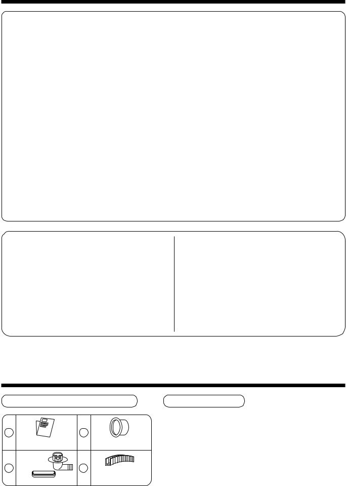
Accessory and Installation Parts |
Refrigerant Piping |
1 |
3 |
|
Outdoor unit |
|
Protective bush |
Installation manual x 1 |
|
(For SM800, SP560, SP800) |
Drain nipple |
|
|
2 |
4 |
Guard material for |
|
|
|
|
|
passage part |
Waterproof rubber cap |
|
(For SM800, SP560, SP800) |
•Piping kit used for the conventional refrigerant cannot be used.
•Use copper pipe with 0.8 mm or more thickness for Ø6.4, Ø9.5, Ø12.7.
Use copper pipe with 1.0 mm or more thickness for Ø15.9.
•Flare nut and flare works are also different from those of the conventional refrigerant. Take out the flare nut attached to the main unit of the air conditioner, and use it.
37
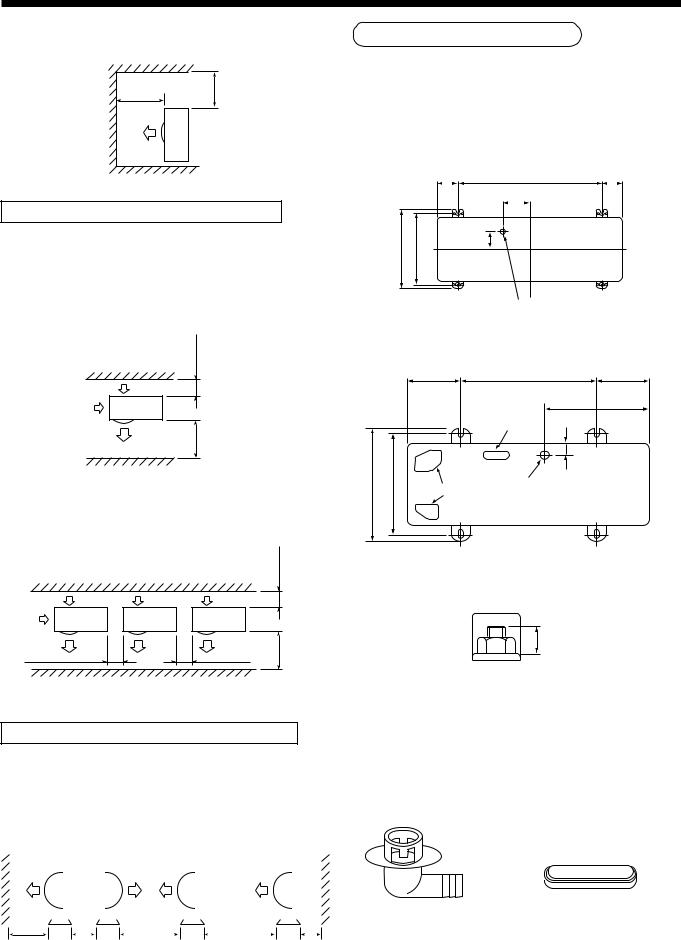
3 SELECTION OF INSTALLATION
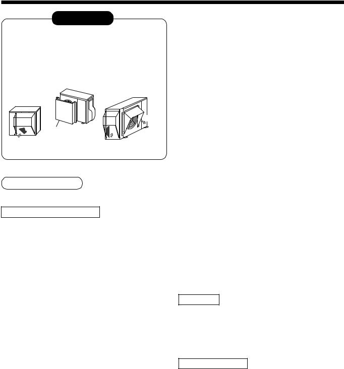
CAUTION
<SP560AT-E, SP800AT-E only>
When using an air conditioner under low outside temperature condition (Outside temp.:–5°C or lower) with COOL mode, prepare a duct or wind shield so that it is not affected by the wind.
<Example>
Suction hood (Side)
Discharge hood
Suction hood (Rear side)
Discharge
Discharge guide |
Fin |
Fin |
|
Suction |
Suction |
|
Before installation
Be careful to the following items before installation.
Length of refrigerant pipe
<SM560AT-E>
Length of refrigerant pipe |
|
|
connected to |
Item |
|
indoor/outdoor unit |
|
|
|
|
|
20m or shorter |
Addition of refrigerant is |
|
unnecessary at the local site. |
||
|
||
|
|
|
*21m to 30m |
<Addition of refrigerant> |
|
Add 20g of refrigerant for every |
||
|
1m of pipe which exceeds 20m. |
|
|
|
*Caution at addition of refrigerant
When the total length of refrigerant pipe exceeds 20m, add 20g/m of refrigerant and the maximum total length of pipe is 30m.
(Max. amount of additional refrigerant is 200g.)
Charge the refrigerant accurately. Overcharge may cause a serious trouble of compressor.
<SM800AT-E>
Length of refrigerant pipe |
|
|
connected to |
Item |
|
indoor/outdoor unit |
|
|
|
|
|
20m or shorter |
Addition of refrigerant is |
|
unnecessary at the local site. |
||
|
||
|
|
|
*21m to 50m |
<Addition of refrigerant> |
|
Add 40g of refrigerant for every |
||
|
1m of pipe which exceeds 20m. |
|
|
|
*Caution at addition of refrigerant
When the total length of refrigerant pipe exceeds 20m, add 40g/m of refrigerant and the maximum total length of pipe is 50m.
(Max. amount of additional refrigerant is 1200g.)
Charge the refrigerant accurately. Overcharge may cause a serious trouble of compressor.
<SP560AT-E>
Length of refrigerant pipe |
|
|
connected to |
Item |
|
indoor/outdoor unit |
|
|
|
|
|
20m or shorter |
Addition of refrigerant is |
|
unnecessary at the local site. |
||
|
||
|
|
|
*21m to 50m |
<Addition of refrigerant> |
|
Add 20g of refrigerant for every |
||
|
1m of pipe which exceeds 20m. |
|
|
|
*Caution at addition of refrigerant
When the total length of refrigerant pipe exceeds 20m, add 20g/m of refrigerant and the maximum total length of pipe is 50m.
(Max. amount of additional refrigerant is 600g.)
Charge the refrigerant accurately. Overcharge may cause a serious trouble of compressor.
<SP800AT-E>
Length of refrigerant pipe |
|
|
connected to |
Item |
|
indoor/outdoor unit |
|
|
30m or shorter |
Addition of refrigerant is |
|
unnecessary at the local site. |
||
|
||
|
|
|
*31m to 50m |
<Addition of refrigerant> |
|
Add 40g of refrigerant for every |
||
|
1m of pipe which exceeds 30m. |
*Caution at addition of refrigerant
When the total length of refrigerant pipe exceeds 30m, add 40g/m of refrigerant and the maximum total length of pipe is 50m.
(Max. amount of additional refrigerant is 800g.)
Charge the refrigerant accurately. Overcharge may cause a serious trouble of compressor.
Air purge
•For air purge, use a vacuum pump.
•Do not use refrigerant charged in the outdoor unit for air purge. (The refrigerant for air purge is not contained in the outdoor unit.)
Electrical cabling
•Be sure to fix the power cables and indoor/outdoor connecting cables with clamps so that they do not contact with the cabinet, etc.
38
Installation Place
•A place which provides a specified space around the outdoor unit.
•A place where the operation noise and discharged air are not given to your neighbors.
•A place that is not exposed to a strong wind.
•A place that does not block a passage.
•When the outdoor unit is installed in an elevated position, be sure to secure its feet.
•There must be sufficient space for carrying in the unit.
•A place where the drain water does not make any problem.
CAUTION
1.Install the outdoor unit at a place where discharge air is not blocked.
2.When an outdoor unit is installed in a place that is always exposed to a strong wind like a coast or on a high story of a building, secure a normal fan operation by using a duct or a wind shield.
3.When installing the outdoor unit in a place that is constantly exposed to a strong wind such as the upper stairs or rooftop of a building, apply the windproof measures referring to the following examples.
1)Install the unit so that its
discharge port faces to the
wall of the building. Keep a 500 distance 500 mm or more
between the unit and the wall surface.
2)Supposing the wind direction during the operation season of the air conditioner, install the unit so that the discharge port is set at right angle to the wind direction.
Strong wind
Strong wind
4.Installation in the following places may result in some troubles. Do not install the unit in such places below.
•A place full of machine oil.
•A place full of sulfuric gas.
•A place where high-frequency radio waves are likely to be generated as from audio equipment, welders, and medical equipment.
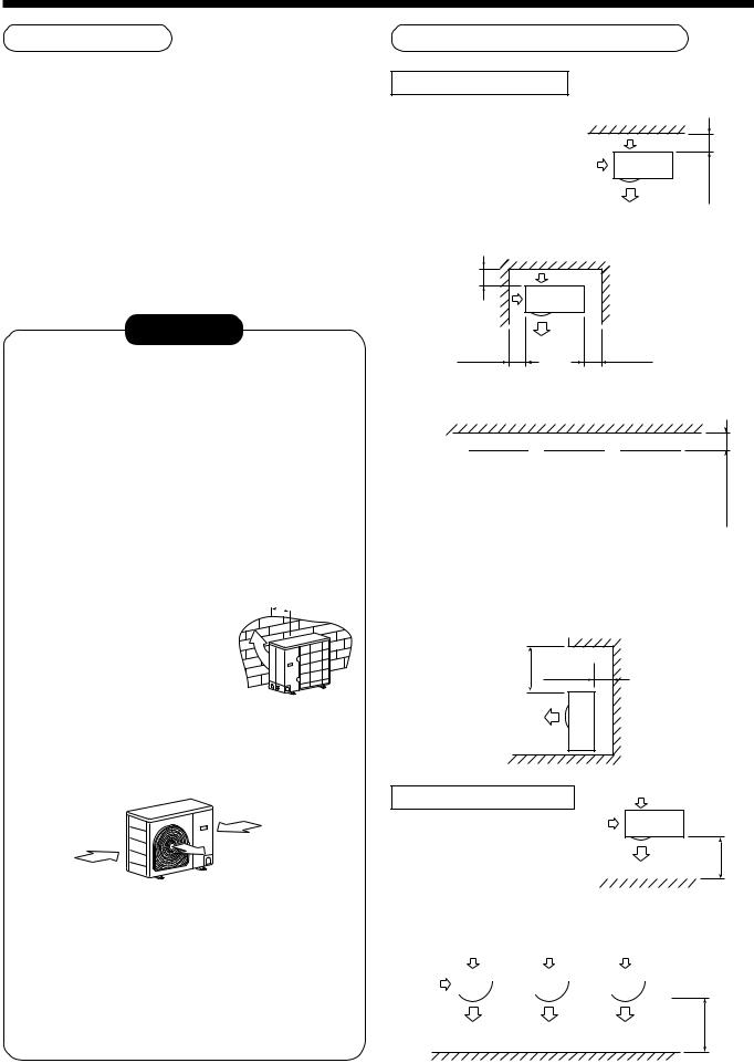
Necessary Space for Installation
Obstacle at rear side
<Upper side is free>
1. Single unit installation
150 or more
2. Obstacles at both right and left sides.
200 ormore |
obstacle should be |
|
The height of the |
|
lower than the height |
|
of the outdoor unit. |
150 |
300 |
or more |
or more |
3. Serial installation of two or more units
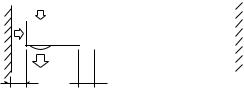


 200 or more
150 |
300 |
300 |
300 |
or more |
or more |
or more |
or more |
The height of the obstacle should be lower than the height of the outdoor unit.
<Obstacle also at the upper side>
500 ormore |
150 |
or more |
|
|
Obstacle at front side
<Upper side is free>
1. |
Single unit installation |
|
500 moreor |
||||||
|
|
||||||||
|
|
|
|
|
|||||
2. |
Serial installation of two or more units |
|
|
||||||
|
|
|
|
|
|
|
|
|
|
|
|
|
|
|
|
|
|
|
|
1000 or more
39
3 SELECTION OF INSTALLATION
<Obstacle also at the upper side>
1000 |
1000 moreor |
or more |
|
Obstacles at both front and rear sides
Open the upper side and both right and left sides. The height of obstacle at both front and rear side, should be lower than the height of the outdoor unit.
<Standard installation>
1. Single unit installation
1000 150 or more or more
2. Serial installation of two or more units
|
|
200 or more |
300 |
300 |
1000 moreor |
or more |
or more |
|
Installation of Outdoor Unit
•Before installation, check strength and horizontality of the base so that abnormal sound does not generate.
•According to the following base diagram, fix the base firmly with the anchor bolts.
(Anchor bolt, nut: M10 x 4 pairs)
<SM560AT-E>
|
90 |
600 |
90 |
|
|
115 |
|
330 |
310 |
76 |
|
Ø28 Drain hole
<SM800AT-E, SP560AT-E, SP800AT-E>
|
|
150 |
|
600 |
150 |
|
|
|
|
|
430 |
|
|
|
Drain hole |
40 |
|
|
|
|
|
|
|
400 |
365 |
Knockout hole |
Drain nipple mounting hole |
||
|
|
|
|
||
Set the out margin of the anchor bolt to 15mm or less.
15 or less
Serial installation at front and rear sides
Open the upper side and both right and left sides. The height of obstacle at both front and rear sides should be lower than the height of the outdoor unit.
<Standard installation>
•In case of draining through the drain hose, attach the following drain nipple and the waterproof rubber cap, and use the drain hose (Inner diam.: 16mm) sold on the market. And also seal the screws securely with silicone material, etc. so that water does not drop down. Some conditions may cause dewing or dripping of water.
|
|
|
|
|
|
|
|
|
|
|
|
|
|
|
|
|
|
|
|
|
|
|
|
|
|
|
|
|
|
|
|
|
|
|
|
|
|
|
|
|
|
|
|
|
|
|
|
|
|
|
|
|
|
|
|
|
|
|
|
|
|
|
|
Drain nipple |
Waterproof rubber cap |
|||
|
|
|
|
|
|
|
|
|
|
|
|
|
|
|
|
|
|
|||||
1000 |
300 |
|
|
1500 |
|
2000 |
|
200 |
|
|||||||||||||
or more |
or more |
|
or more |
|
|
or more |
or more |
|
|
|
|
|
||||||||||
40
<SM560AT-E> |
Refrigerant Piping Connection |
|
 Waterproof rubber cap
Base plate
Drain nipple
<SM800AT-E, SP560AT-E, SP800AT-E>
Knockout hole
Open
Waterproof rubber cap

 Drain nipple
•When there is a possibility of freezing of drain at the cold district or a snowfall area, be careful for drainage ability of drain. The drainage ability increases when a knockout hole on the base plate is opened. (Open the knockout hole to outside using a screwdriver, etc.)
Optional Installation Parts
(Local Procure)
|
Parts name |
Q’ty |
|
|
|
|
|
A |
Refrigerant piping |
Each one |
|
Liquid side : Ø6.35 mm or Ø9.52 mm |
|||
|
Gas side : Ø12.7 mm or Ø15.9 mm |
|
|
|
|
|
|
B |
Pipe insulating material |
1 |
|
(polyethylene foam, 6 mm thick) |
|||
|
|
||
|
|
|
|
C |
Putty, PVC tapes |
Each one |
|
|
|
|
CAUTION
TAKE NOTICE THESE IMPORTANT
4 POINTS BELOW FOR PIPING WORK
1.Keep dust and moisture away from inside the connecting pipes.
2.Tightly connect the connection between pipes and the unit.
3.Evacuate the air in the connecting pipes using VACUUM PUMP.
4.Check gas leak at connected points.
<Piping connection>
Capacity |
Liquid side |
Gas side |
|||
rank |
|
|
|
|
|
Outer |
Thickness |
Outer |
Thickness |
||
RAV- |
|||||
diameter |
diameter |
||||
|
|
|
|
|
|
SM560 |
Ø6.4 |
0.8 |
Ø12.7 |
0.8 |
|
SP560 |
|||||
|
|
|
|
||
|
|
|
|
|
|
SM800 |
Ø9.5 |
0.8 |
Ø15.9 |
1.0 |
|
SP800 |
|||||
|
|
|
|
||
|
|
|
|
|
|
For Reference
If a heating operation would be continuously performed for a long time under the condition that the outdoor temperature is 0°C or lower, draining of defrosted water may be difficult due to freezing of the bottom plate, resulting in a trouble of the cabinet or fan.
It is recommended to procure an anti-freeze heater locally for a safety installation of the air conditioner.
For details, contact the dealer.
41
3 SELECTION OF INSTALLATION
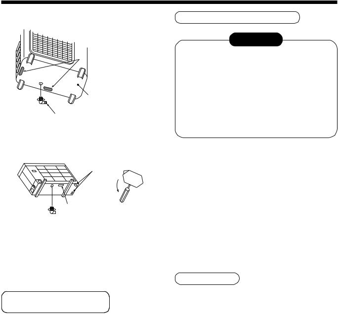
Knockout of Pipe Cover
<SM800AT-E, SP560AT-E, SP800AT-E>
Rear direction
Pipe cover
Side direction
Front direction
Down direction
Knockout procedure
•The indoor/outdoor connecting pipes can be connected to 4 directions.
Take off the knockout part of the pipe cover in which pipes or wires pass through the base plate.
•As shown in the figure, do not remove the pipe cover from the cabinet so that the knockout hole can be easily punched. To knock out, it is easily taken off by hands by punching a position at the lower side of 3 connected parts with screwdriver along the guideline.
•After marking the knockout hole, remove the burr and mount the attached protective bush and guard material for pass-through part in order to protect pipes and wires.
After connecting the pipes, be sure to mount the pipe cover. The pipe cover is easily mounted by cutting off the slit at the lower part of the pipe cover.
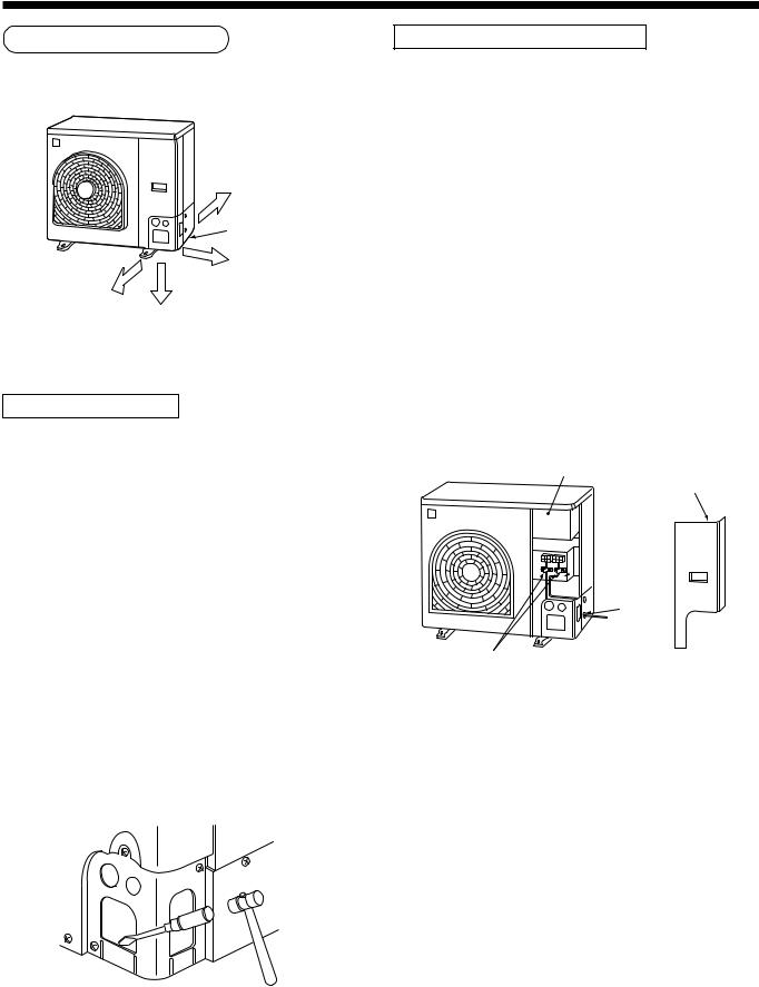
How to remove the front panel
1.Remove screws of the front panel.
2.Pull the front panel downward.
Removing the front panel, the electric parts appear at the front side.
•The metal pipes are attachable to the piping holes. If the size of the used power pipe does not match with the hole, adjust the hole size to match with pipe size.
•Be sure to fix the power cable and indoor/outdoor connecting cable with bundling band sold on the market so that they do not make contact with the compressor and discharge pipe.
(Temperature of the compressor and discharge pipe becomes high.)
In order to avoid the force applied to on the connecting section, be sure to fix the cables to the cord clamps provided on the pipe valve fixing plate and the electric parts box.
Electric parts box
Front panel
Pipe valve
 fixing plate
 Piping
hole
Cord clamp
42
 Loading...