


portege 610ct
Table of contents
 Loading...
TOSHIBA
620CT
Addendum to the 610CT Maintenance Manual
PN: 620-9400PN: 620-9400
PN: 620-9400
PN: 620-9400PN: 620-9400
CARM-B960289-B00

CopyrightCopyright
Copyright
CopyrightCopyright
©1996 by Toshiba Corporation. All rights reserved. Under the copyright laws, this manual cannot be
reproduced in any form without the prior written permission of Toshiba. No patent liability is assumed with
respect to the use of the information contained herein.
PORTÉGÉ 620CT, Addendum to the 610 CT Maintenance Manual
First edition November 1996
DisclaimerDisclaimer
Disclaimer
DisclaimerDisclaimer
The information contained in this manual is subject to change without notice.
Toshiba Corporation and Toshiba America Information Systems, Inc., assume no liability for damages
incurred directly or indirectly from errors, omissions, or discrepancies in connection with the furnishing,
performance, or use of this material.
TrademarksTrademarks
Trademarks
TrademarksTrademarks
IBM, PC/AT, PS/2, OS/2 and VGA are trademarks of IBM Corporation.
MS-DOS and Windows are registered trademarks of Microsoft Corporation.
Intel and Pentium are registered trademarks of Intel Corporation.
Lotus is a registered trademark of Lotus Development Corporation.
Novell and NetWare are registered trademarks of Novell, Inc.
UNIX is a registered trademark of X/Open Company Ltd.
Sound Blaster and Pro are trademarks of Creative Technology Ltd.
Centronics is a registered trademark of Centronics Data Computer Corporation.
All other properties are trademarks or registered trademarks of their respective holders.
ii 620 Maintenance Manual Addendum
About this Addendum
This addendum is a supplement to the T oshiba 610CT Maintenance Manual. The information
contained in this publication covers features, field replaceable units, and disassembly/
reassembly of the T oshiba 620CT computer. For information on troubleshooting, tests and
diagnostics, board layout, pin assignments, etc., please refer to the 610CT Maintenance
Manual.
SAFETY PRECAUTIONS
Four types of messages are used in this manual to bring important
information to your attention. Each of these messages will be italicized
and identified as shown below.
DANGER: "Danger" indicates the existence of a hazard that could result in death
or serious bodily injury if the safety instruction is not observed.
WARNING: "Warning" indicates the existence of a hazard that could result in
bodily injury if the safety instruction is not observed.
CAUTION: "Caution" indicates the existence of a hazard that could result in
property damage if the safety instruction is not observed.
NOTE: A "Note" contains general information that relates to safe maintenance
services.
Improper repair of the computer may result in safety hazards. Toshiba
requires service technicians and authorized dealers or service providers
to ensure the following safety precautions are strictly adhered to.
❑ Be sure to fasten screws securely with the right screwdriver. If a
screw is not fully fastened, it could come loose, creating a danger
of a short circuit, which could cause overheating, smoke or fire.
❑ If you replace the battery pack, RTC battery or backup battery, be
sure to use only the same model battery or an equivalent battery
recommended by Toshiba. Installation of the wrong battery can
cause the battery to explode.
620 Maintenance Manual Addendum iii

TT
abab
T
TT
Chapter 1 Hardware OverviewChapter 1 Hardware Overview
Chapter 1 Hardware Overview
Chapter 1 Hardware OverviewChapter 1 Hardware Overview
1.1 Features..................................................................................................................... 1-1
1.2 System Unit Block Diagram ..................................................................................... 1-4
1.3 3.5-inch External Floppy Disk Drive ........................................................................ 1-8
1.4 2.5-inch Hard Disk Drive.......................................................................................... 1-9
1.5 Keyboard................................................................................................................. 1-10
1.6 TFT Color LCD ......................................................................................................1-11
1.7 Power Supply.......................................................................................................... 1-13
1.8 Batteries .................................................................................................................. 1-14
Chapter 2 Troubleshooting ProceduresChapter 2 Troubleshooting Procedures
Chapter 2 Troubleshooting Procedures
Chapter 2 Troubleshooting ProceduresChapter 2 Troubleshooting Procedures
See the 610CT Maintenance Manual
Chapter 3 Tests and DiagnosticsChapter 3 Tests and Diagnostics
Chapter 3 Tests and Diagnostics
Chapter 3 Tests and DiagnosticsChapter 3 Tests and Diagnostics
le of Contentsle of Contents
ab
le of Contents
abab
le of Contentsle of Contents
See the 610CT Maintenance Manual
Chapter 4 Replacement ProceduresChapter 4 Replacement Procedures
Chapter 4 Replacement Procedures
Chapter 4 Replacement ProceduresChapter 4 Replacement Procedures
4.1 General...................................................................................................................... 4-1
4.2 The Battery Pack ...................................................................................................... 4-6
4.3 Memory Module ....................................................................................................... 4-8
4.4 PC Card .................................................................................................................. 4-11
4.5 Keyboard................................................................................................................. 4-13
4.6 Hard Disk Drive (HDD) ......................................................................................... 4-16
4.7 Top Cover with Display Assembly.......................................................................... 4-18
4.8 RTC and Backup Batteries ..................................................................................... 4-21
4.9 Membrane Switch ................................................................................................... 4-23
4.10 Sound Board ........................................................................................................... 4-24
4.11 Power Supply Board...............................................................................................4-26
4.12 System Board.......................................................................................................... 4-28
4.13 LED Board and Speaker......................................................................................... 4-30
4.14 Display Mask .......................................................................................................... 4-32
4.15 FL Inverter Board ................................................................................................... 4-34
4.16 TFT Color Display Module..................................................................................... 4-36
4.17 Fluorescent Lamp Unit (FL) ................................................................................... 4-38
iv 620 Maintenance Manual Addendum

AppendicesAppendices
Appendices
AppendicesAppendices
Appendix A Handling the LCD Module*
Appendix B Board Layout*
Appendix C Pin Assignments*
Appendix D Keyboard Scan/Character Codes*
Appendix E Key Layouts*
Appendix F Wiring Diagrams*
Appendix G BIOS Rewrite Programs*
*See the 610CT Maintenance Manual
620 Maintenance Manual Addendum v

Chapter 1Chapter 1
Chapter 1
Chapter 1Chapter 1
HarHar
Har
HarHar
dd
ware Overware Over
d
ware Over
dd
ware Overware Over
vievie
vie
vievie
ww
w
ww

1-ii 620 Maintenance Manual Addendum

Chapter 1 ContentsChapter 1 Contents
Chapter 1 Contents
Chapter 1 ContentsChapter 1 Contents
1.1 Features..................................................................................................................... 1-1
1.2 System Unit Block Diagram ..................................................................................... 1-4
1.3 3.5-inch External Floppy Disk Drive (FDD)............................................................. 1-8
1.4 2.5-inch Hard Disk Drive (HDD) ............................................................................. 1-9
1.5 Keyboard................................................................................................................. 1-10
1.6 TFT Color LCD ...................................................................................................... 1-11
1.6.1 LCD Module............................................................................................... 1-11
1.6.2 Fluorescent Lamp (FL) Inverter Board....................................................... 1-12
1.7 Power Supply.......................................................................................................... 1-13
1.8 Batteries .................................................................................................................. 1-14
1.8.1 Main Battery ............................................................................................... 1-14
1.8.2 Battery Charging Control............................................................................ 1-15
1.8.3 Backup Battery ........................................................................................... 1-16
1.8.4 RTC Battery................................................................................................ 1-16
FiguresFigures
Figures
FiguresFigures
Figure 1-1 Computer ...................................................................................................... 1-3
Figure 1-2 System unit configuration ............................................................................. 1-3
Figure 1-3 System board block diagram ......................................................................... 1-4
Figure 1-4 3.5-inch external FDD................................................................................... 1-8
Figure 1-5 2.5-inch HDD................................................................................................1-9
Figure 1-6 Keyboard..................................................................................................... 1-10
Figure 1-7 TFT color LCD........................................................................................... 1-11
TablesTables
Tables
TablesTables
Table 1-1 3.5-inch external FDD specifications ............................................................ 1-8
Table 1-2 2.5-inch HDD specifications ......................................................................... 1-9
Table 1-3 TFT color LCD specifications .................................................................... 1-11
Table 1-4 FL inverter board specifications.................................................................. 1-12
Table 1-5 Power supply board output rating............................................................... 1-13
Table 1-6 Battery specifications.................................................................................. 1-14
Table 1-7 Time required for quick charges ................................................................. 1-15
Table 1-8 Backup battery charging/data preservation time......................................... 1-16
Table 1-9 RTC battery charging/data preservation time ............................................. 1-16
620 Maintenance Manual Addendum 1-iii

1.11.1
1.1
1.11.1
The 620CT uses extensive Large Scale Integration (LSI), and Complementary Metal-Oxide
Semiconductor (CMOS) technology to provide minimum size and weight, low power usage,
and high reliability. This computer incorporates the following features and benefits:
FeaturesFeatures
Features
FeaturesFeatures
❑ Microprocessor
Uses an Intel Pentium processor 100 MHz with VRT (Voltage Reduction Technology) that operates at 2.9/3.3 volts. The math co-processor and 16 KB cache memory
are integrated into Pentium.
❑ Disk storage
An internal 1.3 billion byte (1.26 GB) Hard Disk Drive (HDD). An external 3.5-inch
Floppy Disk Drive (FDD) supports 2HD (1.44 MB) floppy disks and 2DD (720 KB)
floppy disks.
❑ Memory
Standard with 8 MB of EDO (Extend Data Out) DRAM. This includes 640 KB of
conventional memory and 7360 KB of extended memory, which can be utilized as
expanded memory compatible with the Lotus/Intel/Microsoft Expanded Memory
Specification (LIM-EMS).
❑ LCD
A 10.4-inch TFT (Thin Film Transistor) color LCD 800 x 600 pixels. The built-in
display controller supports full color capability and up to 1024 x 768 resolution on an
external CRT.
❑ Keyboard
An-easy-to-use 82/84-key keyboard provides a numeric keypad overlay for fast numeric data entry or for cursor and page control. The keyboard supports software that
uses a 101- or 102-key enhanced keyboard.
❑ Batteries
Three different batteries: a Lithium-Ion main battery, a backup battery (for memory
backup), and an RTC battery (Real Time Clock).
❑ Exp. memory slot
An optional 8, 16, or 32 MB memory module can be installed in the memory slot.
620 Maintenance Manual Addendum 1-1

❑ Parallel port
Can be used to connect a Centronics compatible printer or other parallel device. The
port supports ECP (Extended Capabilities Port) conforming to IEEE·1284.
❑ Serial port
The serial controller is 16550UART compatible. This standard, 9-pin serial port can be
used to connect such serial devices as a serial printer, serial mouse, or external modem.
❑ Port replicator port
A port replicator port which enables connection of a port replicator or external monitor adapter. The port replicator allows connection of a PS/2 mouse, PS/2 keyboard,
external monitor, printer, DC IN, serial I/O, and an external FDD. The display adapter
allows connection of an external monitor.
❑ External FDD port
The external FDD port lets you connect an external FDD.
❑ PC card slot
A PC card slot supports up to two Personal Computer Memory Card International
Association (PCMCIA) release 2.0 standard cards. The upper and lower slots can each
accommodate one Type II (5.0 mm) card. The lower slot can accommodate one Type
III (10.5 mm) card when the upper slot is empty.
❑ AccuPoint
A pointer control stick, located in the center of the keyboard, provides convenient
control of the cursor without requiring desk space for a mouse.
❑ Sound System
Sound Blaster Pro compatible sound system to record sound and play it back with a
built-in microphone and speaker. The sound system provides a volume control dial,
headphone jack, and microphone jack.
1-2 620 Maintenance Manual Addendum
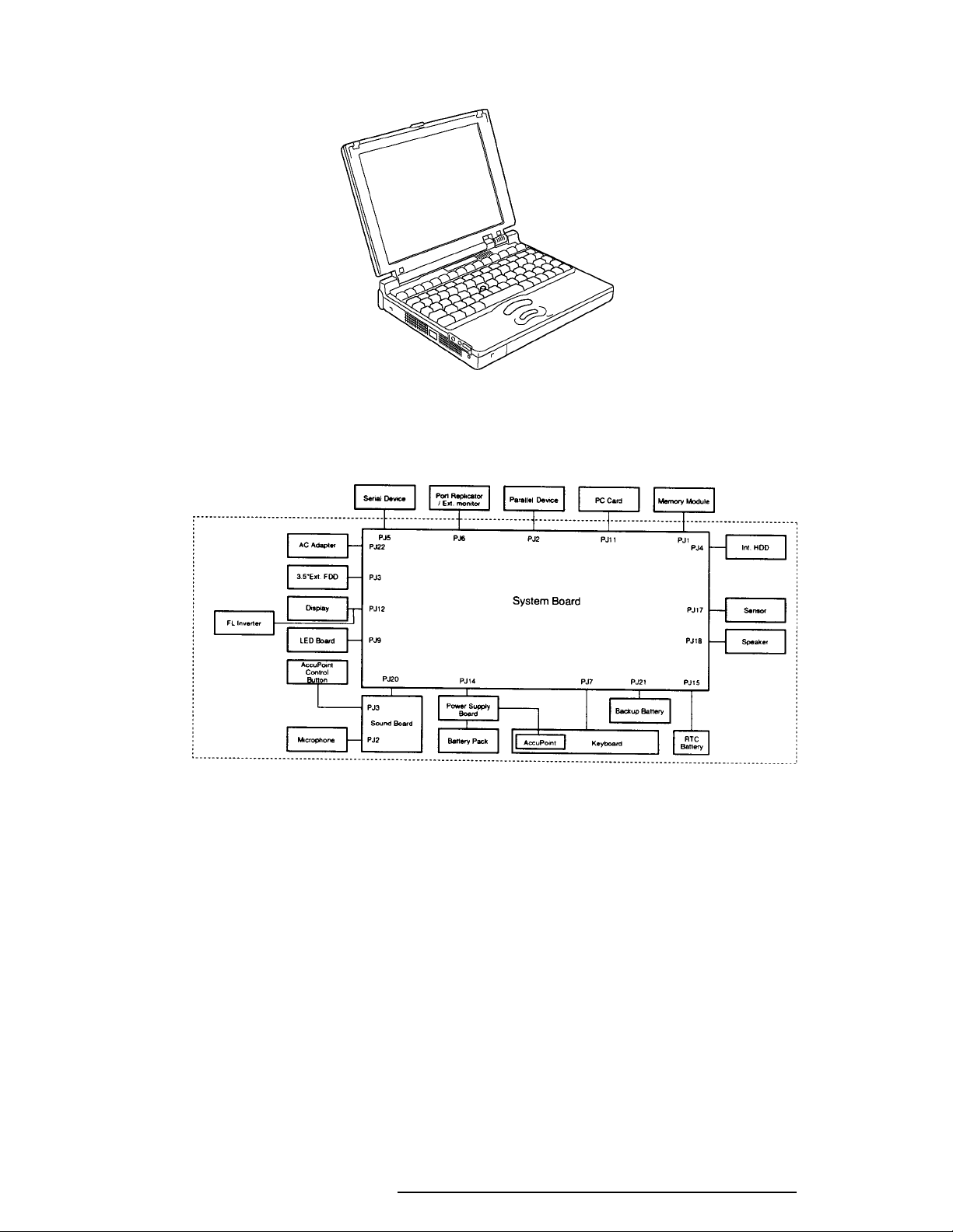
The computer is shown in Figure 1-1.
Figure 1-1 Computer
The system configuration is shown in Figure 1-2.
Figure 1-2 System unit configuration
620 Maintenance Manual Addendum 1-3
1.21.2
1.2
1.21.2
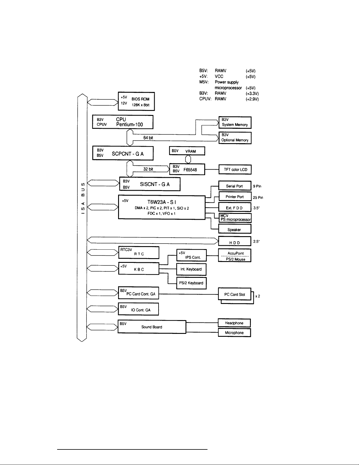
Figure 1-3 is a block diagram of the system unit.
System Unit BlocSystem Unit Bloc
System Unit Bloc
System Unit BlocSystem Unit Bloc
k Diak Dia
k Dia
k Diak Dia
gramgram
gram
gramgram
Figure 1-3 System board block diagram
1-4 620 Maintenance Manual Addendum

The system board is composed of the following major components:
❑ One Intel Pentium-100 MHz with VRT 64-bit microprocessor
Intel Pentium processor operates at 100 MHz and 2.9 volts and 3.3 volts. It incorporates a math coprocessor and a 16KB cache.
❑ Standard RAM
8 MB, four 1Mx16-bit EDO DRAM chips
3.3 volt operation
No parity bit
Access time 60 ns
Data transfer is 64-bit width
❑ BIOS ROM (Flash EEPROM)
128 KB (One 128Kx8-bit chip) memory
64 KB in the ROM are used for system BIOS
32 KB in the ROM are used for VGA BIOS
32 KB in the ROM are reserved
Access time 150 ns
Data transfer is 8-bit width
❑ Video RAM
1 MB (Two 256Kx16-bit DRAMs)
5 volt operation
❑ Optional memory
One expansion memory slot is available for 8, 16, and 32 MB memory modules,
which may consist of 1 MBx16-bit EDO DRAM chips. Total maximum
memory size is 40 MB (if a 32 MB memory module is installed).
3.3 volt operation
No parity bit
Access time 60 ns
Data transfer is 64-bit width
❑ One super integration (SI-T6W23A)
Consists of the following components:
Two DMACs 82C37 equivalent
Two PICs 82C59 equivalent
Two SIOs 16550 equivalent (One SIO is not used)
One PIT 82C54 equivalent
One FDC TC8565 equivalent
One VFO TC8568 equivalent
One I/O port decode
One SIO port control
One printer port control supported ECP
One FDD control
One speaker control
One power communication control
620 Maintenance Manual Addendum 1-5

❑ System Controller Gate Array (SCPCNT-GA)
This gate array has the following functions:
CPU control
SMI control
CPU clock control
Memory control
64-bit bus memory control
32-bit bus memory control
Bus control
64-bit data bus <==> 32-bit data bus
32-bit local bus control
Address latch control
I/O register control
Processing speed control
❑ ISA Bus Controller Gate Array (SISCNT-GA)
This gate array has the following functions:
Bus control
32-bit data bus <==> 16-bit data bus
ISA bus interface control
ISA bus access control
DMAC control
DMA address generation
I/O control
Memory control
ISA bus interface control
Refresh address generation
I/O register control
Suspend/Resume sequence
❑ PC Card Controller Gate Array
This gate array has the following functions:
PCMCIA memory card control
PCMCIA I/O card control
❑ I/O Controller Gate Array
This gate array has the following functions:
Internal Communication control
KBC, main CPU communication register file
KBC interrupt control
Others
KBC communication control. Contrast adjust,
speaker volume adjust PWM control, Sound board
interface, BIOS-ROM interface, SMI control
❑ Video Controller
Chips & Technologies F65548 is used.
Controls internal TFT color LCD and external SVGA compatible CRT.
1-6 620 Maintenance Manual Addendum

❑ Keyboard Controller (KBC)
One M38802M4 chip is used.
This KBC includes the keyboard scan controller and keyboard interface controller.
The KBC controls the internal keyboard, external keyboard, AccuPoint, and PS/2
mouse.
❑ AccuPoint Controller (IPSC)
One U43SC10 chip is used.
Provides simultaneous control of both the AccuPoint and a PS/2 mouse.
❑ Real Time Clock (RTC)
One T9934 chip is used.
The T9934 has 128 bytes of memory. Fourteen bytes of memory are used for the
calendar and clock. The remaining 114 bytes are used for the system configuration
data.
620 Maintenance Manual Addendum 1-7
1.31.3
1.3
1.31.3
3.5-inc3.5-inc
3.5-inc
3.5-inc3.5-inc
h External Flopph External Flopp
h External Flopp
h External Flopph External Flopp
y Disk Drive (FDD)y Disk Drive (FDD)
y Disk Drive (FDD)
y Disk Drive (FDD)y Disk Drive (FDD)
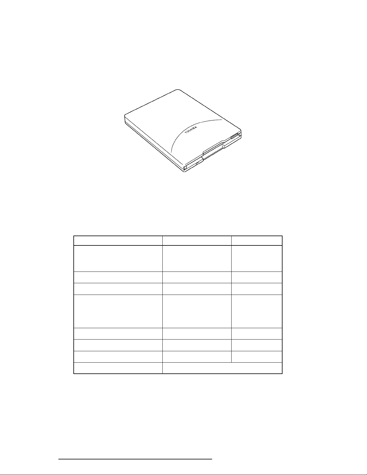
The 3.5-inch external FDD is a thin, high-performance reliable drive that supports 720-KB
(formatted) 2DD and 1.44-MB (formatted) 2HD 3.5-inch floppy disks.
The FDD is shown in Figure 1-4.
Figure 1-4 3.5-inch external FDD
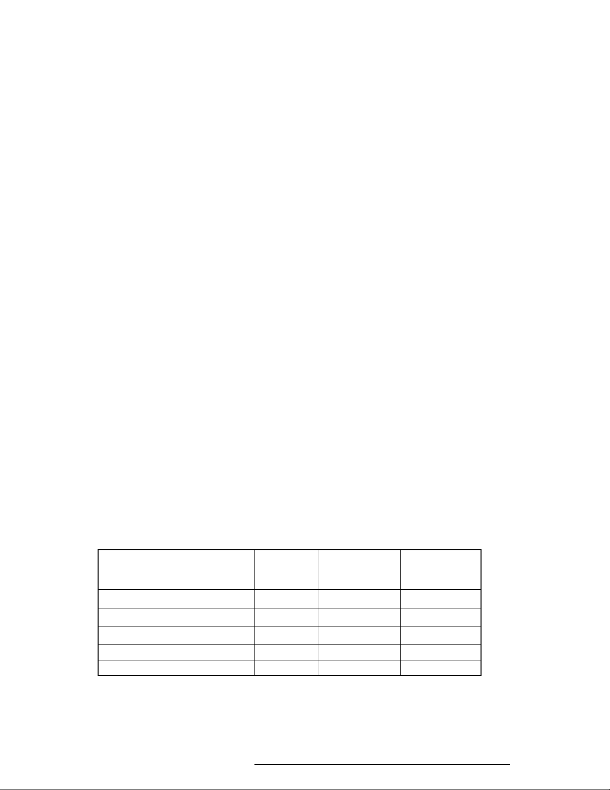
The specifications for the FDD are listed in Table 1-1.
Table 1-1 3.5-inch external FDD specifications
Item 2-MB mode 1-MB mode
Storage capacity (KB)
Unformatted 2,000 1,000
Formatted 1,440 720
Number of heads 2 2
Number of cylinders 80 80
Access time (ms)
Track to track 3 3
Average 181 181
Head settling time 15 15
Recording track density (tpi) 135 135
Data transfer rate (Kbps) 500 250
Rotation speed (rpm) 300 300
Recording method Modified Frequency Modulation (MFM)
1-8 620 Maintenance Manual Addendum
1.41.4
1.4
1.41.4
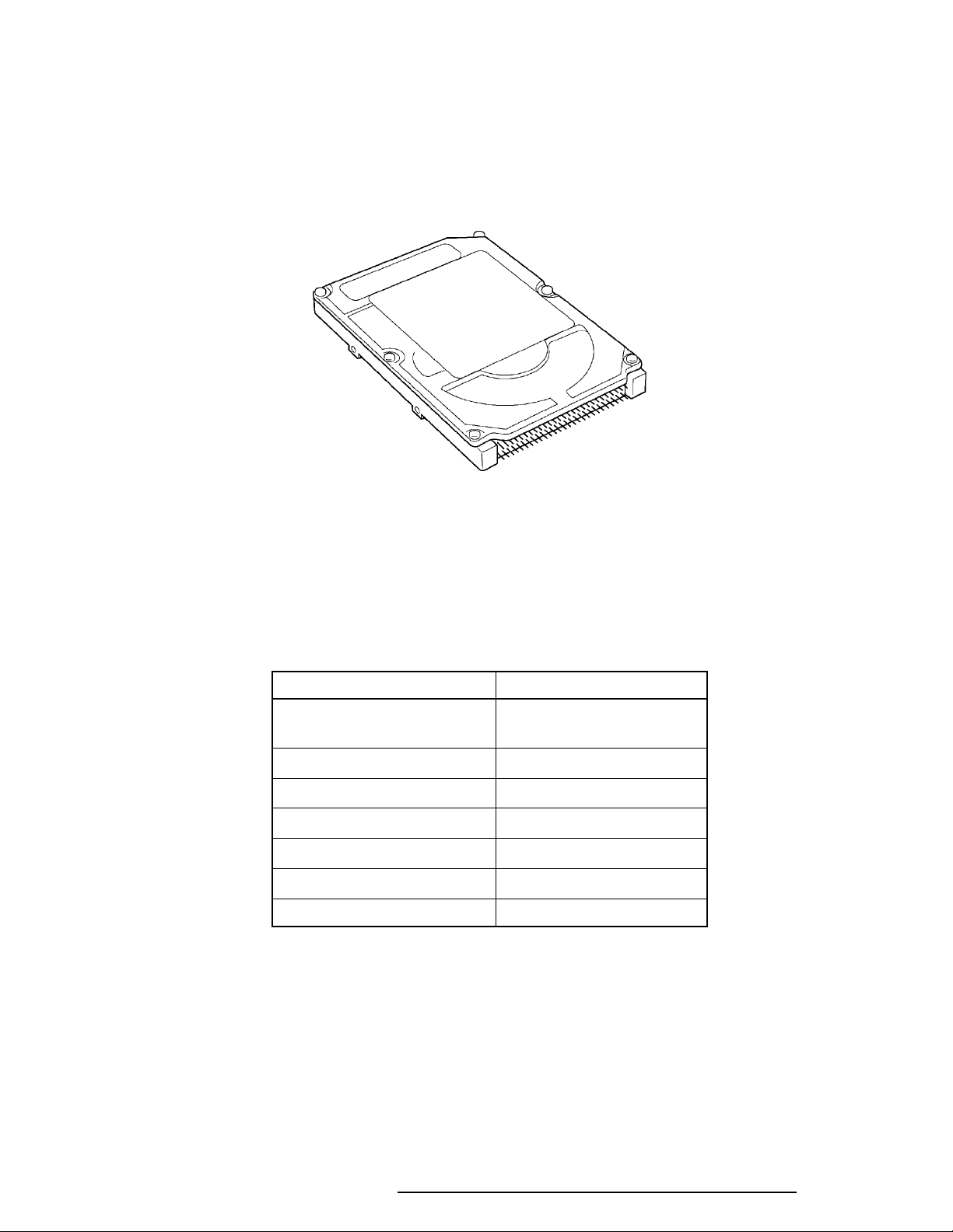
The HDD is a random access non-volatile storage device. It has a non-removable 1.3 billion
byte (1.26GB), 2.5-inch magnetic disk and mini-winchester type magnetic heads.
The HDD is shown in Figure 1-5.
2.5-inc2.5-inc
2.5-inc
2.5-inc2.5-inc
h Harh Har
h Har
h Harh Har
d Disk Drive (HDD)d Disk Drive (HDD)
d Disk Drive (HDD)
d Disk Drive (HDD)d Disk Drive (HDD)
Figure 1-5 2.5-inch HDD
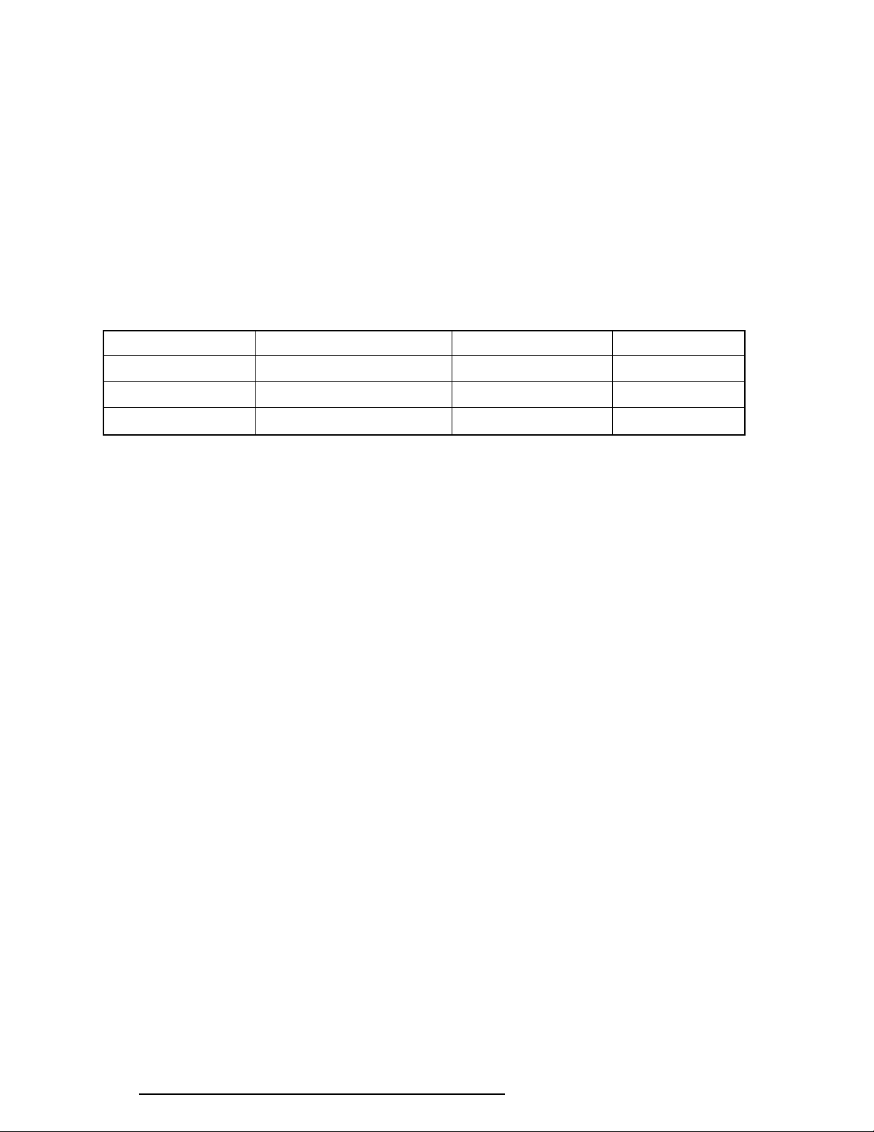
Specifications for the HDD are listed in Table 1-2.
Table 1-2 2.5-inch HDD specifications
Items (MK1301MAV)
Storage capacity (GB)
Formatted 1.26
Number of disks 3
Data heads 16
Data surfaces 6
Bytes per sector 512
Rotation speed (rpm) 4200
Recording method 8-9 RLL
620 Maintenance Manual Addendum 1-9
1.51.5
1.5
1.51.5
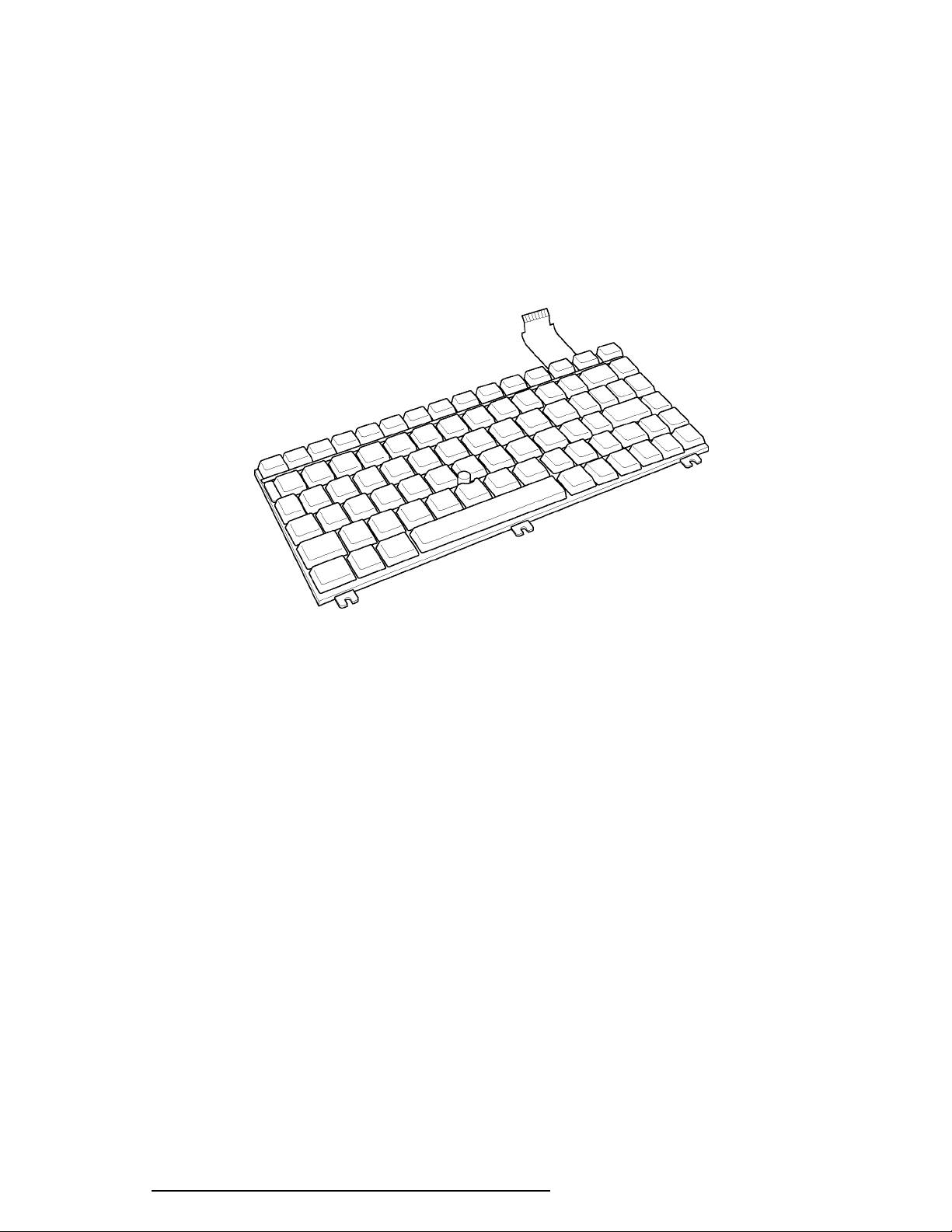
The 82-(USA) or 84-(European) key keyboard is mounted on the system unit. The keyboard
is connected to the keyboard controller on the system board through a 25-pin flat cable. The
pointer control stick, located in the center of the keyboard, provides convenient control of the
cursor without requiring desk space for a mouse. The keyboard is shown in Figure 1-6.
See Appendix E of the Portégé 610CT Maintenance Manual for optional keyboard configurations.
KK
K
KK
ee
e
ee
yboaryboar
yboar
yboaryboar
dd
d
dd
Figure 1-6 Keyboard
1-10 620 Maintenance Manual Addendum
1.61.6
1.6
1.61.6
TFT Color LCDTFT Color LCD
TFT Color LCD
TFT Color LCDTFT Color LCD
The TFT Color Liquid Crystal Display (LCD) contains an LCD module, a Fluorescent Lamp
(FL), and an FL inverter board.
1.6.11.6.1
1.6.1
1.6.11.6.1
LCD ModuleLCD Module
LCD Module
LCD ModuleLCD Module
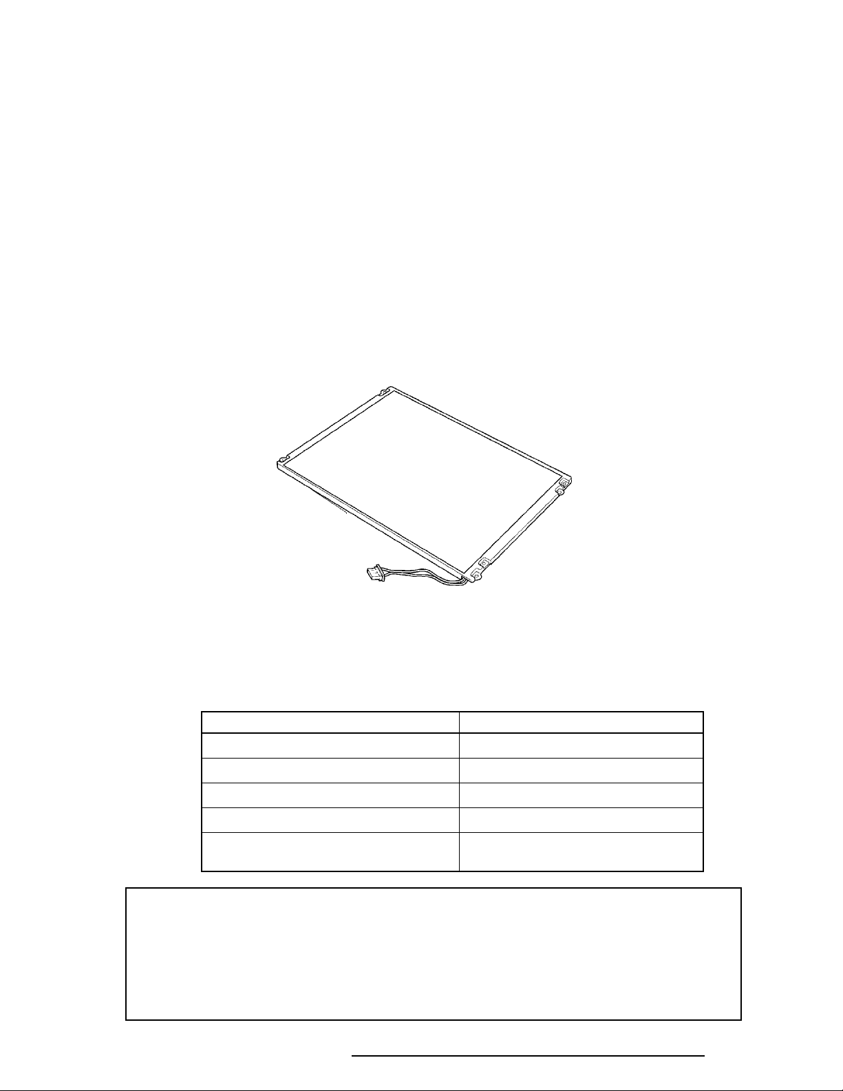
The TFT color LCD supports 800 x 600 pixels with an internal display controller and 256K
colors for graphics and characters. This controller includes the functions of Video Graphics
Array (VGA) and Super VGA (SVGA) for display.
The LCD receives 9-bit data signals, data enable signals, and a shift clock for data transmission. All signals are CMOS-level compatible.
The TFT LCD is shown in Figure 1-7.
Figure 1-7 TFT color LCD
The specifications for the LCD are listed in Table 1-3.
Table 1-3 TFT color LCD specifications
Item Specifications
Number of dots (dots) 800 x 600
Dot pitch (mm) 0.264 x 0.264
Display area (mm) 211.2 x 158.4
Contrast 100
FL current (mA) 4.6/4.0/2.8/2.4*
*NOTE: The FL currents at power on are:
Bright Semi-bright
AC adapter connected 4.6 mA 2.8 mA
AC adapter not connected 4.0 mA 2.4 mA
(The settings at power on do not change even if the AC adapter connection
changes.)
(Bright/Semi-bright)
620 Maintenance Manual Addendum 1-11
1.6.21.6.2
1.6.2
1.6.21.6.2
Fluorescent Lamp (FL) Inverter BoardFluorescent Lamp (FL) Inverter Board
Fluorescent Lamp (FL) Inverter Board
Fluorescent Lamp (FL) Inverter BoardFluorescent Lamp (FL) Inverter Board
The FL inverter board supplies high frequency current to light the LCD Fluorescent Lamp.
The specifications for the FL inverter are listed in Table 1-4.
Table 1-4 FL inverter board specifications
Item Specifications
Input Voltage (VDC) 4 to 5.5
Power (W) 4.8
Output Voltage (Vrms) 1,100
Current (mA) 4.6/4.0/2.8/2.4*
(Bright/Semi-bright)
*NOTE: The FL currents at power on are:
Bright Semi-bright
AC adapter connected 4.6 mA 2.8 mA
AC adapter not connected 4.0 mA 2.4 mA
(The settings at power on do not change even if the AC adapter connection
changes.)
1-12 620 Maintenance Manual Addendum
1.71.7
1.7
1.71.7
The power supply provides five kinds of voltages to the system board. The power supply has
one microprocessor that operates at 500 KHz and contains the following functions:
PP
oo
wer Supplwer Suppl
P
o
wer Suppl
PP
oo
wer Supplwer Suppl
1. Determines if the AC adapter or battery is connected to the computer.
2. Controls the LED icon and speaker.
3. Determines when the battery is fully charged.
4. Controls power on/off.
5. Searches for low/high voltage at power I/O areas.
6. Calculates the remaining battery capacity.
7. Displays error status on the LED.
8. Controls boot mode and resume mode reset.
yy
y
yy
9. Controls power to the LCD/FL based on the LCD panel sensor.
10. Controls intensity of the backlight FL.
11. Conserves data in the system buffer when power is off.
12. Controls the main battery’s power flow.
13. Controls alarm beeps for power supply errors.
The power supply output rating is specified in Table 1-5.
Table 1-5 Power supply output rating
DC Regulation
Use for Name voltage tolerance
(V) (%)
System logic, FDD, HDD, Display VCC +5 ±5
RS-232C P+12V +12 ±5
RAM B3V +3.3 ±5
VGA,I/O B5V +5 ±5
CPU CPUV, B3V +2.9, +3.3 ±5
620 Maintenance Manual Addendum 1-13
1.81.8
1.8
1.81.8
The computer has three types of batteries:
Battery specifications are listed in Table 1-6.
BatteriesBatteries
Batteries
BatteriesBatteries
❑ Main battery pack
❑ Backup battery
❑ Real Time Clock (RTC) battery
Table 1-6 Battery specifications
Battery name Material Output voltage Capacity
Main battery Lithium-Ion 10.8 V 4,000 mAH
Backup battery Nickel Metal Hydride 6.0 V 110 mAH
RTC battery Nickel Metal Hydride 3.6 V 30 mAH
1.8.11.8.1
1.8.1
1.8.11.8.1
The removable main battery pack is the computer’s main power source when the AC adapter
is not attached. The main battery recharges the backup battery when the system power is on.
The backup and main battery maintain the state of the computer when you enable
AutoResume.
❑ Battery Indicator
Main BatteryMain Battery
Main Battery
Main BatteryMain Battery
The battery indicator is located on the front of the computer. The indicator shows the
status of the removable battery pack, power supply, and AC adapter.
The status of each can be determined by color:
Orange The battery is being charged. (AC adapter is attached.)
Green The battery is fully charged. (AC adapter is attached.)
No light The AC adapter is disconnected from the computer. The AC adapter is
connected, but it cannot charge the battery for one of the following reasons:
• The battery is extremely hot. Allow the computer and the battery to
reach room temperature before attempting to charge the battery.
• The battery is almost fully discharged. The battery will not begin
charging immediately in this state, it will begin charging a few minutes
after the AC adapter is connected.
• The AC adapter is not receiving power.
1-14 620 Maintenance Manual Addendum
1.8.21.8.2
1.8.2
1.8.21.8.2
Battery Charging ControlBattery Charging Control
Battery Charging Control
Battery Charging ControlBattery Charging Control
Battery charging is controlled by a power supply microprocessor that is mounted on the
power supply. The microprocessor controls whether the charge is on or off and detects a full
charge when the AC adapter and battery are attached to the computer. The system charges
the battery using quick charge or trickle charge.
❑ Quick Battery Charge
When the AC adapter is attached, there are two types of charge: quick charge when
the system is powered off and trickle charge when the system is powered on.
Table 1-7 Time required for quick charges
Charging time
Quick charge About 4 hours
(power off)
Trickle charge About 5 to 8 hours
(power on)
If one of the following occurs, the battery quick-charge process stops.
1. The battery becomes fully charged.
2. The AC adapter or battery is removed.
3. The battery or AC adapter output voltage is abnormal.
4. The charge current is abnormal.
❑ Trickle Battery Charge
When the main battery is fully charged and the AC adapter is attached, the power
supply microprocessor automatically changes quick charge to trickle charge.
620 Maintenance Manual Addendum 1-15
1.8.31.8.3
1.8.3
1.8.31.8.3
Backup BatteryBackup Battery
Backup Battery
Backup BatteryBackup Battery
The backup battery maintains data for resume. The power source used to back-up the resume
data is determined according to the following priority:
AC adapter > Main battery > Backup battery
The backup battery is charged by the main battery or AC adapter when the system is powered
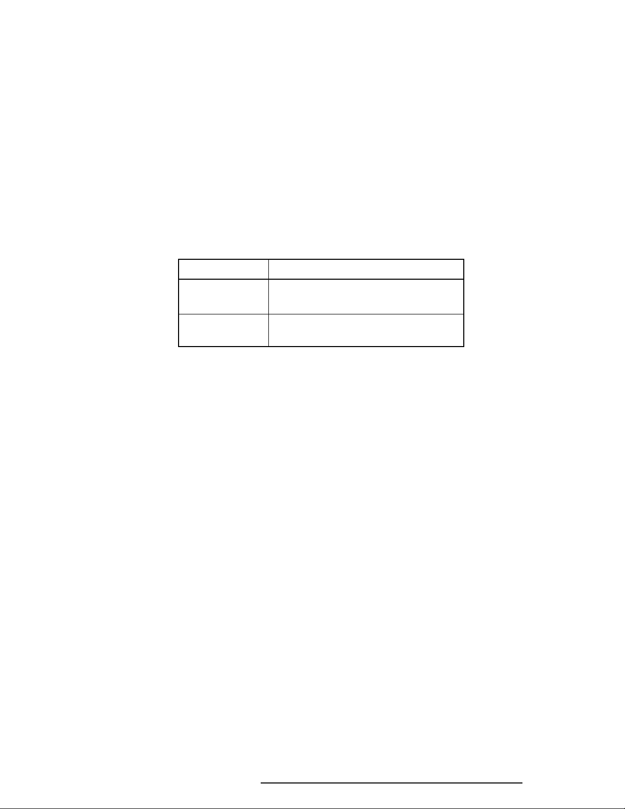
on. Table 1-8 shows the charging time and data preservation period of the backup battery.
Table 1-8 Backup battery charging/data preservation time
Time
Charging Time Power On 40 H
Power Off (with AC Adapter) 40 H
Power Off (Without AC Adapter) Doesn’t charge
Data preservation period (full charge) 1.5 H
1.8.41.8.4
1.8.4
1.8.41.8.4
RTC BatteryRTC Battery
RTC Battery
RTC BatteryRTC Battery
The RTC battery provides power to keep the current date, time, and other setup information
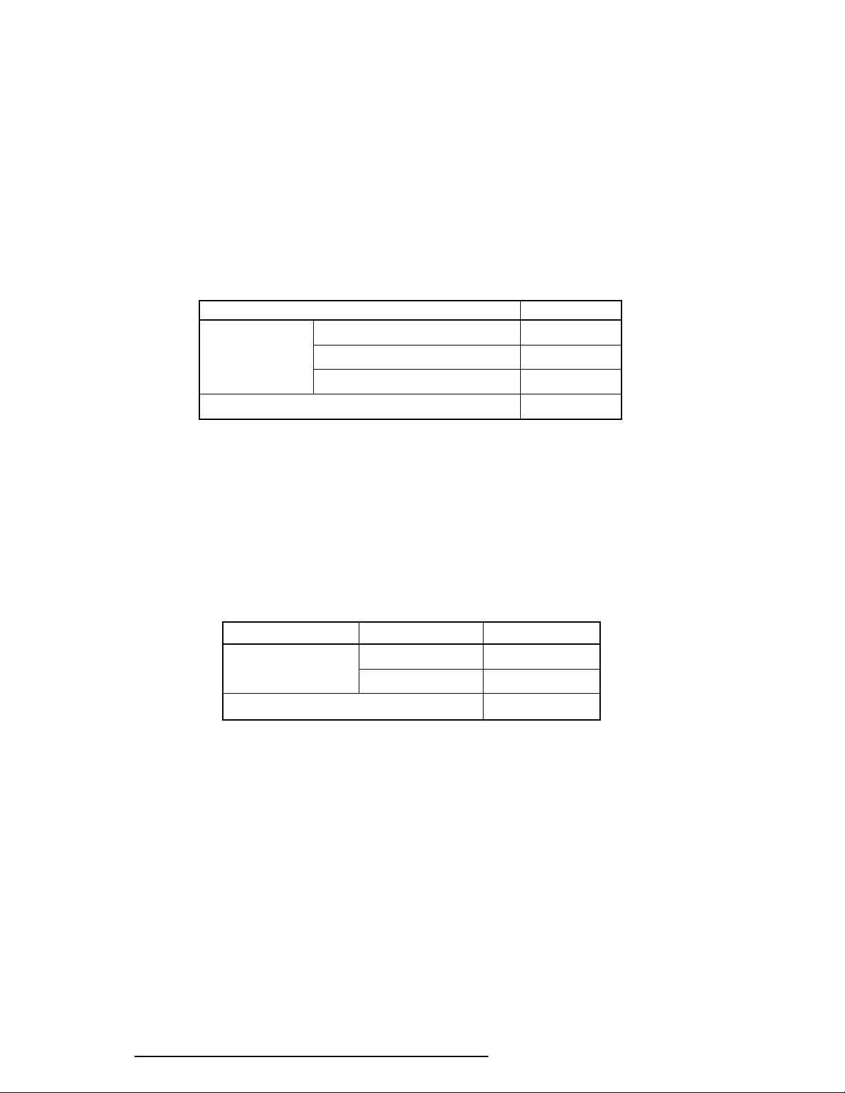
in memory while the computer is turned off. Table 1-9 shows the charging time and data
preservation period of the RTC battery.
Table 1-9 RTC battery charging/data preservation time
Time
Charging Time Power On 70 H
Power Off Dosen’t charge
Data preservation period (full charge) 1 month
1-16 620 Maintenance Manual Addendum

Chapter 4
Replacement Procedures

4-ii 620 Maintenance Manual Addendum

Chapter 4 ContentsChapter 4 Contents
Chapter 4 Contents
Chapter 4 ContentsChapter 4 Contents
4.1 General...................................................................................................................... 4-1
Safety Precautions..................................................................................................... 4-2
Before You Begin ..................................................................................................... 4-3
Disassembly Procedures............................................................................................ 4-4
Assembly Procedures ................................................................................................ 4-4
Tools and Equipment ................................................................................................ 4-5
Screw Tightening Torque ......................................................................................... 4-5
4.2 The Battery Pack ...................................................................................................... 4-6
Removing the Battery Pack ...................................................................................... 4-6
Installing the Battery Pack ........................................................................................ 4-7
4.3 Memory Module ....................................................................................................... 4-8
Removing the Memory Module ................................................................................ 4-8
Installing the Memory Module................................................................................ 4-10
4.4 PC Card .................................................................................................................. 4-11
Removing the PC Card ........................................................................................... 4-11
Installing the PC Card ............................................................................................. 4-12
4.5 Keyboard................................................................................................................. 4-13
Removing the Keyboard ......................................................................................... 4-13
Installing the Keyboard ........................................................................................... 4-15
4.6 Hard Disk Drive (HDD) ......................................................................................... 4-16
Removing the HDD ................................................................................................ 4-16
Installing the HDD .................................................................................................. 4-17
4.7 Top Cover and Display Assembly........................................................................... 4-18
Removing the Top Cover and Display Assembly.................................................... 4-18
Installing the Top Cover and Display Assembly ..................................................... 4-20
4.8 RTC and Backup Batteries ..................................................................................... 4-21
Removing the RTC and Backup Batteries .............................................................. 4-21
620 Maintenance Manual Addendum 4-iii

Installing the RTC and Backup Batteries................................................................ 4-22
4.9 Membrane Switch ................................................................................................... 4-23
Removing the Membrane Switch ............................................................................ 4-23
Installing the Membrane Switch.............................................................................. 4-23
4.10 Sound Board ........................................................................................................... 4-24
Removing the Sound Board.................................................................................... 4-24
Installing the Sound Board...................................................................................... 4-25
4.11 Power Supply Board............................................................................................... 4-26
Removing the Power Supply Board........................................................................ 4-26
Installing the Power Supply Board ......................................................................... 4-27
4.12 System Board.......................................................................................................... 4-28
Removing the System Board................................................................................... 4-28
Installing the System Board .................................................................................... 4-29
4.13 LED Board and Speaker......................................................................................... 4-30
Removing the LED Board and Speaker.................................................................. 4-30
Installing the LED Board and Speaker ................................................................... 4-31
4.14 Display Mask .......................................................................................................... 4-32
Removing the Display Mask ................................................................................... 4-32
Installing the Display Mask..................................................................................... 4-33
4.15 FL Inverter Board ................................................................................................... 4-34
Removing the FL Inverter Board............................................................................ 4-34
Installing the FL Inverter Board ............................................................................. 4-35
4.16 TFT Color Display Module..................................................................................... 4-36
Removing the TFT Color Display Module ............................................................. 4-36
Installing the TFT Color Display Module ............................................................... 4-37
4.17 Fluorescent Lamp Unit (FL) ................................................................................... 4-38
Removing the FL Unit ............................................................................................ 4-38
Installing the FL Unit .............................................................................................. 4-39
4-iv 620 Maintenance Manual Addendum

4.18 Microphone............................................................................................................. 4-40
Removing the Microphone...................................................................................... 4-40
Installing the Microphone ....................................................................................... 4-40
4.19 Display Cable .......................................................................................................... 4-41
Removing the Display Cable ................................................................................... 4-41
Installing the Display Cable..................................................................................... 4-41
FiguresFigures
Figures
FiguresFigures
Figure 4-1 Unlocking the battery pack ........................................................................... 4-6
Figure 4-2 Lifting out the battery pack........................................................................... 4-6
Figure 4-3 Installing the battery pack ............................................................................. 4-7
Figure 4-4 Removing the memory module socket cover................................................ 4-8
Figure 4-5 Removing the memory module ..................................................................... 4-9
Figure 4-6 Inserting the memory module ..................................................................... 4-10
Figure 4-7 Removing the PC card ................................................................................ 4-11
Figure 4-8 Installing the PC card.................................................................................. 4-12
Figure 4-9 Releasing the keyboard cover ..................................................................... 4-13
Figure 4-10 Removing the keyboard screw .................................................................... 4-14
Figure 4-11 Removing the keyboard .............................................................................. 4-14
Figure 4-12 Removing the keyboard cable ..................................................................... 4-15
Figure 4-13 Removing the HDD with bracket ............................................................... 4-16
Figure 4-14 Removing the HDD .................................................................................... 4-17
Figure 4-15 Removing the bottom cover screws............................................................ 4-18
Figure 4-16 Releasing the top cover latches................................................................... 4-19
Figure 4-17 Separating the top cover and display assembly ........................................... 4-19
Figure 4-18 Removing the RTC and backup batteries.................................................... 4-21
Figure 4-19 Removing the membrane switch ................................................................. 4-23
Figure 4-20 Removing the sound board ......................................................................... 4-24
Figure 4-21 Removing the power supply board ............................................................. 4-26
Figure 4-22 Removing the system board ........................................................................ 4-28
Figure 4-23 Removing the LED board and speaker assembly ........................................ 4-30
Figure 4-24 Removing the LED board ........................................................................... 4-30
Figure 4-25 Removing the seals and screws ................................................................... 4-32
Figure 4-26 Removing the display mask......................................................................... 4-33
620 Maintenance Manual Addendum 4-v

Figure 4-27 Removing the FL inverter board ................................................................. 4-34
Figure 4-28 Removing the display module screws ......................................................... 4-36
Figure 4-29 Removing the LCD ..................................................................................... 4-37
Figure 4-30 Removing the FL unit screws ..................................................................... 4-38
Figure 4-31 Removing the FL unit ................................................................................. 4-39
Figure 4-32 Removing the FL ........................................................................................ 4-39
Figure 4-33 Removing the microphone .......................................................................... 4-40
Figure 4-34 Removing the display cable......................................................................... 4-41
4-vi 620 Maintenance Manual Addendum
Loading...