


MMY-MAP1004FT8Z-E
Toshiba MMY-MAP1004FT8Z-E, MMY-MAP1204FT8Z-E, MMY-MAP0804FT8-E, MMY-MAP1004FT8ZG-E, MMY-MAP1204FT8ZG-E User Manual
...
English
AIR CONDITIONER (MULTI TYPE)
Outdoor Unit
Model name:
MMY-MAP0804FT8-E
MMY-MAP1004FT8-E
MMY-MAP1204FT8-E
MMY-MAP1404FT8-E
MMY-MAP0804FT8Z-E
MMY-MAP1004FT8Z-E
MMY-MAP1204FT8Z-E
MMY-MAP1404FT8Z-E
MMY-MAP0804FT8ZG-E
MMY-MAP1004FT8ZG-E
MMY-MAP1204FT8ZG-E
MMY-MAP1404FT8ZG-E
Installation Manual
For commercial use
–1–
Original instruction
Contents
1 Precautions for safety . . . . . . . . . . . . . . . . . . . . . . . . . . . . . . . . . . . . . . . . . . . . . . . . . . 3
2 Accessory parts . . . . . . . . . . . . . . . . . . . . . . . . . . . . . . . . . . . . . . . . . . . . . . . . . . . . . . . 5
3 Installation of new refrigerant air conditioner. . . . . . . . . . . . . . . . . . . . . . . . . . . . . . . 5
4 Selection of installation place. . . . . . . . . . . . . . . . . . . . . . . . . . . . . . . . . . . . . . . . . . . . 6
5 Carrying in the outdoor unit . . . . . . . . . . . . . . . . . . . . . . . . . . . . . . . . . . . . . . . . . . . . . 7
6 Installation of the outdoor unit . . . . . . . . . . . . . . . . . . . . . . . . . . . . . . . . . . . . . . . . . . . 8
7 Refrigerant piping . . . . . . . . . . . . . . . . . . . . . . . . . . . . . . . . . . . . . . . . . . . . . . . . . . . . 10
8 Electric wiring. . . . . . . . . . . . . . . . . . . . . . . . . . . . . . . . . . . . . . . . . . . . . . . . . . . . . . . . 19
9 Address setting . . . . . . . . . . . . . . . . . . . . . . . . . . . . . . . . . . . . . . . . . . . . . . . . . . . . . . 23
10 How to set up the cooling only indoor unit . . . . . . . . . . . . . . . . . . . . . . . . . . . . . . . . 30
11 Test run . . . . . . . . . . . . . . . . . . . . . . . . . . . . . . . . . . . . . . . . . . . . . . . . . . . . . . . . . . . . . 31
12 Troubleshooting . . . . . . . . . . . . . . . . . . . . . . . . . . . . . . . . . . . . . . . . . . . . . . . . . . . . . . 32
13 Machine card and logbook . . . . . . . . . . . . . . . . . . . . . . . . . . . . . . . . . . . . . . . . . . . . . 34
ADOPTION OF NEW REFRIGERANT
This Air Conditioner uses R410A an environmentally friendly refrigerant.
1-EN 2-EN
–2–
Thank you for purchasing this Toshiba air conditioner.
This Installation Manual describes the installation method of the outdoor unit. For installation of indoor units, follow the
Installation Manual supplied with the indoor unit.
Moreover, as this installation manual includes the important articles concerning the “Machinery” Directive (Directive 2006/42/
EC), please read through the manual and make sure you understand it. After installation, give this Installation Manual, the
Owner’s Manual and the Installation Manual supplied with the indoor unit to the customer and tell the customer to keep them
safe.
Prepare an exclusive power source for indoor units, independent to that for outdoor units.
Y-shaped branching joints or a branching header (separately purchased) are required for connecting pipes between indoor and
outdoor units. Choose either of them considering the system capacity concerning piping. For installing branching pipes, refer to
the installation manual of the Y-shaped branching unit or branching header (separately purchased).
Outdoor connecting branching joints are required for connecting between outdoor units.
Generic Denomination: Air Conditioner
Definition of Qualified Installer or Qualified Service Person
The air conditioner must be installed, maintained, repaired and removed by a qualified installer or qualified service person.
When any of these jobs is to be done, ask a qualified installer or qualified service person to do them for you.
A qualified installer or qualified service person is an agent who has the qualifications and knowledge described in the table
below.
Definition of Protective Gear
When the air conditioner is to be transported, installed, maintained, repaired or removed, wear protective gloves and ‘safety’
work clothing.
In addition to such normal protective gear, wear the protective gear described below when undertaking the special work de tailed
in the table below.
Failure to wear the proper protective gear is dangerous because you will be more susceptible to injury, burns, electric shocks
and other injuries.
Agent Qualifications and knowledge which the agent must have
Qualified installer
• The qualified installer is a pers on who installs, maintains, relocate s and removes the air conditione rs made by
Toshiba Carrier Corporation. He or she has been trained to install, maintain, relocate and remove the air
conditioners made by Toshiba Car rier Corporation or, alternatively , he or she has been instructed in such
operations by an individual or individuals who have been trained and is thus thoroughly acquainted with the
knowledge related to these operations.
• The qualified installer who is allowe d to do the electrical work involved in installation, relocation and removal has
the qualifications pertaining to this electrical work as stipulated by the local laws and regulations, and he or she is
a person who has been trained in matters relating to electrical work on the air conditioners made by Toshiba Carrier
Corporation or, alternatively, he or she has been instructed in such matters by an individual or individuals who have
been trained and is thus thoroughly acquainted with the knowledge related to this work.
• The qualified installer who is allowe d to do the refrigerant hand ling and piping work involved in installation,
relocation and removal has the qualifications pertaining to this refrigerant handling and piping work as stipulated
by the local laws and regulations, and he or she is a person who has been trained in matters relating to refrigerant
handling and piping work on the air conditioners made by Toshiba Carrier Corporation or, alternatively, he or she
has been instructed in such matters by an individual or individuals who have been trained and is thus thoroughly
acquainted with the knowledge re lated to this work.
• The qualified installer who is allowed to work at heights has been trained in matters relating to working at heights
with the air conditioners made by Toshiba Carrier Corporation or, alternatively, he or she has been instructed in
such matters by an individual or individuals who have been trained and is thus thoroughly acquainted with the
knowledge related to this work.
Qualified service
person
• The qualified service person is a person wh o installs, repairs, maintains, relocates and removes the air condition ers
made by Toshiba Carrier Corporation . He or she has been trained to install, repair, maintain, relocate and remove
the air conditioners made by Toshiba Carrier Corporation or, alternatively, he or she has been instructed in such
operations by an individual or individuals who have been trained and is thus thoroughly acquainted with the
knowledge related to these operations.
• The qualified service person who is allo wed to do the electrical work involve d in installation, repair, relocation an d
removal has the qualifications pertaining to this electrical work as stipulated by the local laws and regulations, and
he or she is a person who has been trained in matters relating to electrical work on the air conditioners made by
Toshiba Carrier Corporation or, alternatively, he or she has been instructed in such matters by an individual or
individuals who have been trained and is thus thoroughly acquainted with the knowledge related to this work.
• The qualified service person who is allowed to do the refrigerant handling and pipi ng work involved in installation,
repair, relocation and removal has the qualifications pertaining to this refrigerant handling and piping work as
stipulated by the local laws and regulations, and he or she is a person who has been trained in matters relating to
refrigerant handling and piping work on the air conditioners made by Toshiba Carrier Corporation or, alternatively,
he or she has been instructed in such matters by an individual or individuals who have been trained and is thus
thoroughly acquainted with the knowledge related to this work.
• The qualified service person who is allowed to work at heights has been trained in matters relating to working at
heights with the air conditioners made by Toshiba Carrier Corporation or, alternatively, he or she has been
instructed in such matters by an individual or individuals who have been trained and is thus thoroughly acquainted
with the knowledge related to this work.
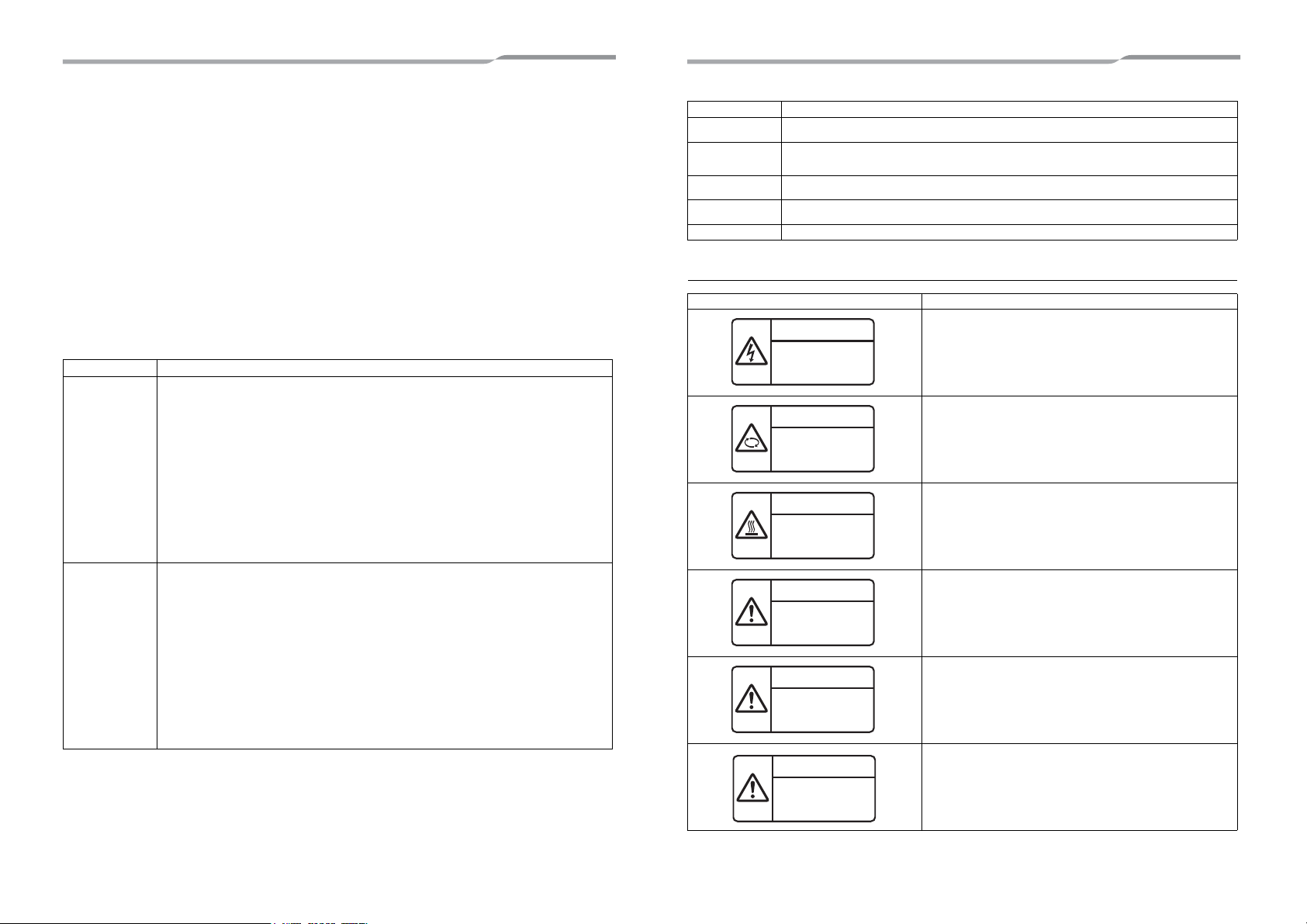
Warning indications on the air conditioner unit
Work undertaken Protective gear worn
All types of work
Protective gloves
‘Safety’ working clothing
Electrical-related
work
Gloves to provide protec tion for electricians and from h eat
Insulating shoes
Clothing to provide protection from electric shock
Work done at heights
(50 cm or more)
Helmets for use in industry
Transportation of
heavy objects
Shoes with additional protective toe cap
Repair of outdoor unit Gloves to provide protectio n for electricians and from heat
Warning indication Description
WARNING
ELECTRICAL SHOCK HAZARD
Disconnect all remote electric power supplies before servicing.
WARNING
Moving parts.
Do not operate unit with grille removed.
Stop the unit before the servicing.
CAUTION
High temperature parts.
You might get burned when removing this panel.
CAUTION
Do not touch the aluminium fins of the unit.
Doing so may result in injury.
CAUTION
BURST HAZARD
Open the service valves before the operation, otherwise there might be the
burst.
CAUTION
Do not climb onto the fan guard.
Doing so may result in injury.
WARNING
ELECTRICAL SHOCK HAZARD
Disconnect all remote
electric power supplies
before servicing.
WARNING
Moving parts.
Do not operate unit with grille
removed.
Stop the unit before the servicing.
CAUTION
High temperature parts.
You might get burned
when removing this panel.
CAUTION
Do not touch the aluminum
fins of the unit.
Doing so may result in injury.
CAUTION
BURST HAZARD
Open the service valves before
the operation, otherwise there
might be the burst.
CAUTION
Do not climb onto the
fan guard.
Doing so may result in injury.
3-EN 4-EN
–3–
1 Precautions for safety
The manufacturer shall not assume any liability for the damage caused by not observing the description of this manual.
WARNING
General
• Before starting to install the air conditioner, read through the Installation Manual carefully, and follow its instructions to install
the air conditioner. Otherwise, falling down of the unit may occur, or the unit may cause noise, vibration or water leakage.
• Only a qualified installer(*1) or qualified service person(*1) is allowed to do installationwork. If installation is carried out by
an unqualified individual, a fire, electric shocks, injury, water leakage, noise and/or vibration may result.
• If using separately sold products, make sure to use Toshiba specified products only. Using unspecified products may cause
fire, electric shock, water leak or other failure.
• Do not use any refrigerant different from the one specified for complement or replacement. Otherwise, abnormally high
pressure may be generated in the refrigeration cycle, which may result in a failure or explosion of the product or an injury
to your body.
• Before opening the service panel of the outdoor unit, set the circuit breaker to the OFF position. Failure to set the circuit
breaker to the OFF position may result in electric shocks through contact with the interior parts. Only a qualified installer(*1)
or qualified service person(*1) is allowed to remove the service panel of the outdoor unit and do the work required.
• Before carrying out the installation, maintenance, repair or removal work, be sure to set the circuit breakers for both the
indoor and outdoor units to the OFF position. Otherwise, electric shock may result.
• Place a “Work in progress” sign near the circuit breaker while the installation, maintenance, repair or removal work is being
carried out. There is a danger of electric shocks if the circuit breaker is set to ON by mistake.
• Only a qualified installer(*1) or qualified service person(*1) is allowed to undertake work at heights using a stand of 50 cm
or more or to remove the intake grille of the indoor unit to undertake work.
• Wear protective gloves and safety work clothing during installation, servicing and removal.
• Do not touch the aluminium fin of the outdoor unit. You may injure yourself if you do so. If the fin must be touched for some
reason, first put on protective gloves and safety work clothing, and then proceed.
• Do not climb onto or place objects on top of the outdoor unit. You may fall or the objects may fall off of the outdoor unit and
result in injury.
• When working at height, put a sign in place so that no-one will approach the work location before proceeding with the work.
Parts or other objects may fall from above, possibly injuring a person below. Also, be sure that workers put on helmets.
• When cleaning the filter or other parts of the outdoor unit, set the circuit breaker to OFF without fail, and place a “Work in
progress” sign near the circuit breaker before proceeding with the work.
• When working at heights, put a sign in place so that no-one will approach the work location, before proceeding with the
work. Parts and other objects may fall from above, possibly injuring a person below.
• The refrigerant used by this air conditioner is the R410A.
• You shall ensure that the air conditioner is transported in stable condition. If you find any part of the product broken, contact
your dealer.
• Do not disassemble, modify, repair or move the product yourself. Doing so may cause fire, electric shock, injury or water
leaks. Ask a qualified installer or qualified service person to do any repairs or to move the product.
Selection of installation location
• If you install the unit in a small room, take appropriate measures to prevent the refrigerant from exceeding the limit
concentration even if it leaks. Consult the dealer from whom you purchased the air conditioner when you implement the
measures. Accumulation of highly concentrated refrigerant may cause an oxygen deficiency accident.
• Do not install in a location where flammable gas may leaks are possible. If the gas should leak and accumulate around the
unit, it may ignite and cause a fire.
• When transporting the air conditioner, wear shoes with protective toe caps, protective gloves and other protective clothing.
• When transporting the air conditioner, do not take hold of the bands around the packing carton. You may injure yourself if
the bands should break.
• Install the indoor unit at least 2.5 m above the floor level since otherwise the users may injure themselves or receive electric
shocks if they poke their fingers or other objects into the indoor unit while the air conditioner is running.
• Do not place any combustion appliance in a place where it is directly exposed to the wind of air conditioner, otherwise it may
cause imperfect combustion.
• Places where the operation sound of the outdoor unit may cause a disturbance. (Especially at the boundary line with
a neighbour, install the air conditioner while considering the noise.)
Installation
• Follow the instructions in the Installation Manual to install the air conditioner. Failure to follow these instructions may cause
the product to fall down or topple over or give rise to noise, vibration, water leakage or other failure.
• The designated bolts (M12) and nuts (M12) for securing the outdoor unit must be used when installing the unit.
• Install the outdoor unit property in a location that is durable enough to support the weight of the outdoor unit. Insufficient
durability may cause the outdoor unit to fall, which may result in injury.
• Install the unit in the prescribed manner for protection against strong wind and earthquake. Incorrect installation may result
in the unit falling down, or other accidents.
• Be sure to fix the screws back which have been removed for installation or other purposes.
Refrigerant piping
• Install the refrigerant pipe securely during the installation work before operating the air conditioner. If the compressor is
operated with the valve open and without refrigerant pipe, the compressor sucks air and the refrigeration cycles is over
pressurized, which may cause a injury.
• Tighten the flare nut with a torque wrench in the specified manner. Excessive tighten of the flare nut may cause a crack in
the flare nut after a long period, which may result in refrigerant leakage.
• Ventilate the air if the refrigerant gas leaks during installation. If the leaked refrigerant gas comes into contact with fire, toxic
gas may be produced.
• After the installation work, confirm that refrigerant gas does not leak. If refrigerant gas leaks into the room and flows near a
fire source, such as a cooking range, noxious gas may be generated.
• When the air conditioner has been installed or relocated, follow the instructions in the Installation Manual and purge the air
completely so that no gases other than the refrigerant will be mixed in the refrigerating cycle. Failure to purge the air
completely may cause the air conditioner to malfunction.
• Nitrogen gas must be used for the airtight test.
• The charge hose must be connected in such a way that it is not slack.
• If refrigerant gas has leaked during the installation work, ventilate the room immediately. If the leaked refrigerant gas comes
in contact with fire, noxious gas may be generated.
Electrical wiring
• Only a qualified installer(*1) or qualified service person(*1) is allowed to carry out the electrical work of the air conditioner.
Under no circumstances must this work be done by an unqualified individual since failure to carry out the work properly may
result in electric shocks and/or electrical leaks.
• When connecting the electrical wires, repairing the electrical parts or undertaking other electrical jobs, wear gloves to
provide protection for electricians and from heat, insulating shoes and clothing to provide protection from electric shocks.
Failure to wear this protective gear may result in electric shocks.
• When executing address setting, test run, or troubleshooting through the checking window on the electrical control box, put
on insulated heat-proof gloves, insulated shoes and other clothing to provide protection from electric shock. Otherwise you
may receive an electric shock.
• Use wiring that meets the specifications in the Installation Manual and the stipulations in the local regulations and laws. Use
of wiring which does not meet the specifications may give rise to electric shocks, electrical leakage, smoking and/or a fire.
• Check that the product is properly earthed. (grounding work)
Incomplete earthing may cause electric shock.
• Do not connect the earth wire to a gas pipe, water pipe, lightning conductor, or a telephone earth wire.
• After completing the repair or relocation work, check that the ground wires are connected properly.
• Install a circuit breaker that meets the specifications in the installation manual and the stipulations in the local regulations
and laws.
• Install the circuit breaker where it can be easily accessed by the agent.
• When installing the circuit breaker outdoors, install one which is designed to be used outdoors.
• Under no circumstances must the power cable be extended. Connection trouble in the places where the cable is extended
may give rise to smoking and/or a fire.
• Electrical wiring work shall be conducted according to law and regulation in the community and installation manual.
Failure to do so may result in electrocution or short circuit.
• Do not supply power from the power terminal block equipped on the outdoor unit to another outdoor unit. Capacity overflow
may occur on the terminal block and may result in fire.
• When carrying out electric connection, use the wire specified in the Installation Manual and connect and fix the wires
securely to prevent them applying external force to the terminals. Improper connection or fixing may result in fire.
Test run
• Before operating the air conditioner after having completed the work, check that the electrical control box cover of the indoor
unit and service panel of the outdoor unit are closed, and set the circuit breaker to the ON position. You may receive an
electric shock if the power is turned on without first conducting these checks.
• When you have noticed that some kind of trouble (such as when an error display has appeared, there is a smell of burning,
abnormal sounds are heard, the air conditioner fails to cool or heat or water is leaking) has occurred in the air conditioner,
do not touch the air conditioner yourself but set the circuit breaker to the OFF position, and contact a qualified service
person. Take steps to ensure that the power will not be turned on (by marking “out of service” near the circuit breaker, for
instance) until qualified service person arrives. Continuing to use the air conditioner in the trouble status may cause
mechanical problems to escalate or result in electric shocks or other failure.
• After the work has finished, be sure to use an insulation tester set (500 V Megger) to check the resistance is 2 MΩ or more
between the charge section and the non-charge metal section (Earth section). If the resistance value is low, a disaster such
as a leak or electric shock is caused at user’s side.
• Upon completion of the installation work, check for refrigerant leaks and check the insulation resistance and water drainage.
Then conduct a test run to check that the air conditioner is operating properly.
Explanations given to user
• Upon completion of the installation work, tell the user where the circuit breaker is located. If the user does not know where
the circuit breaker is, he or she will not be able to turn it off in the event that trouble has occurred in the air conditioner.
• If you have discovered that the fan grille is damaged, do not approach the outdoor unit but set the circuit breaker to the OFF
position, and contact a qualified service person(*1) to have the repairs done. Do not set the circuit breaker to the ON position
until the repairs are completed.
• After the installation work, follow the Owner’s Manual to explain to the customer how to use and maintain the unit.
5-EN 6-EN
–4–
Relocation
• Only a qualified installer(*1) or qualified service person(*1) is allowed to relocate the air conditioner. It is dangerous for the
air conditioner to be relocated by an unqualified individual since a fire, electric shocks, injury, water leakage, noise and/or
vibration may result.
• When carrying out the pump-down work shut down the compr essor before disconnecting the refrigerant pipe. Disconnecting
the refrigerant pipe with the service valve left open and the compressor still operating will cause air or other gas to be sucked
in, raising the pressure inside the refrigeration cycle to an abnormally high level, and possibly resulting in rupture, injury or
other trouble.
• Never recover the refrigerant into the outdoor unit. Be sure to use a refrigerant recovery machine to recover the refrigerant
when moving or repairing. It is impossible to recover the refrigerant into the outdoor unit. Refrigerant recovery into the
outdoor unit may result in serious accidents such as explosion of the unit, injury or other accidents.
(*1) Refer to the “Definition of Qualified Installer or Qualified Service Person.”
CAUTION
New refrigerant air conditioner installation
• This air conditioner adopts the new HFC refrigerant (R410A) which does not destroy ozone layer.
• The characteristics of R410A refrigerant are; easy to absorb water, oxidizing membrane or oil, and its pressure is approx.
1.6 times higher than that of refrigerant R22. Accompanied with the new refrigerant, refrigerating oil has also been changed.
Therefore, during installation work, be sure that water, dust, former refrigerant, or refrigerating oil does not enter the
refrigerating cycle.
• To prevent charging an incorrect refrigerant and refrigerating oil, the sizes of connecting sections of charging port of the
main unit and installation tools are changed from those for the conventional refrigerant.
• Accordingly the exclusive tools are required for the new refrigerant (R410A).
• For connecting pipes, use new and clean piping designed for R410A, and please care so that water or dust does not enter.
To disconnect the appliance from main power supply.
• This appliance must be connected to the main power supply by means of a switch with a contact separation of at least 3 mm.
The installation fuse (all type can be used) must be used for the power supply line of this conditioner.
7-EN 8-EN
–5–
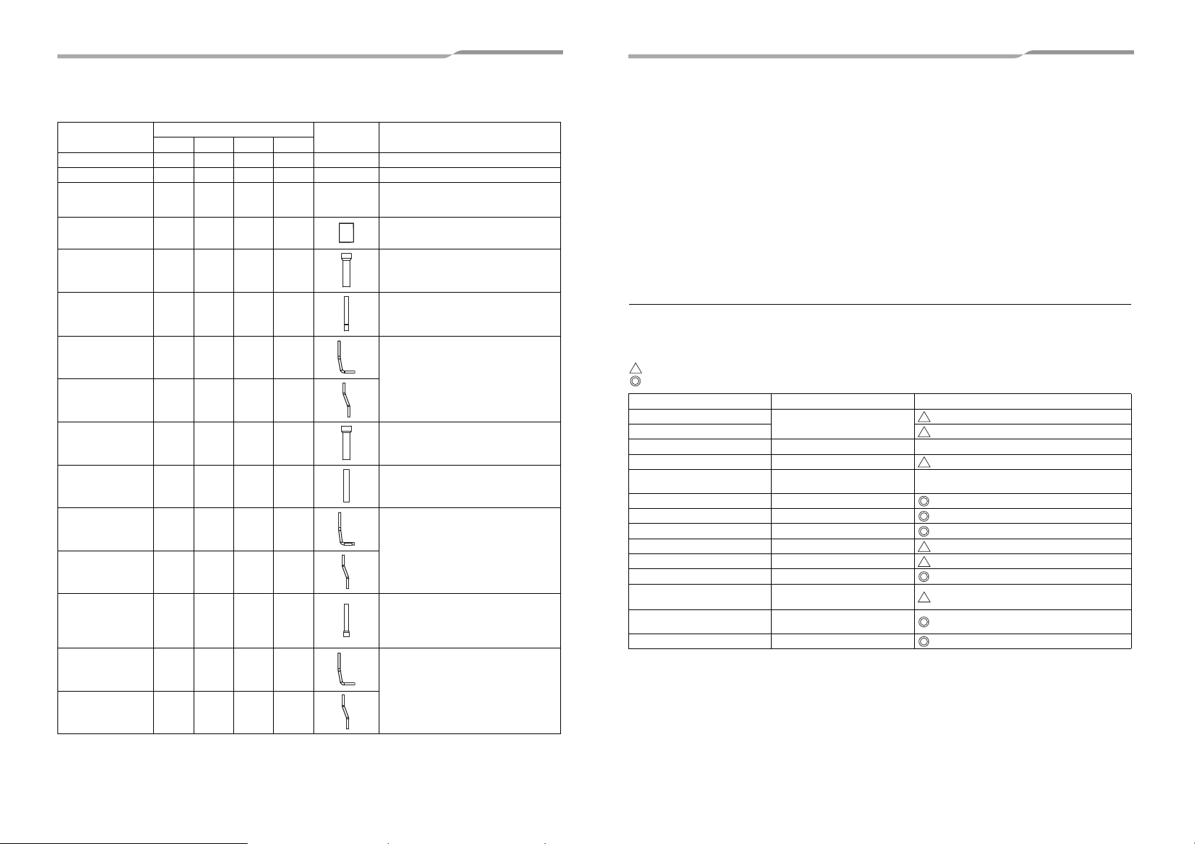
2 Accessory parts
Part name
Q’ty
Shape Usage
MAP080 MAP100 MAP120 MAP140
Owner’s Manual 1 1 1 1 – (Be sure to hand it to the customers.)
Installation Manual 1 1 1 1 – (Be sure to hand it to the customers.)
CD-ROM
(Owner’s manual,
Installation manual)
1111 –
For other languages that do not appear in
this Installation Manual, Please refer to the
enclosed CD-ROM.
F-GAS label 1 1 1 1
Fill the items on the label after adding
refrigerant.
Attached pipe
(Ø22.2 both forward
and downward)
11––
Suction-side gas pipe
Ø25.4 → Ø22.2 pipe fitting
Attached pipe
(Ø15.9 both forward
and downward)
11––
Discharge-side gas pipe
Ø15.9 → Ø19.1 pipe fitting
* Flare the connector on the outdoor unit for
installation
Attached pipe
(Ø12.7 for draw-out
forward)
11––
Liquid-side connection pipe
* Flare the connector on the outdoor unit for
installation
Attached pipe
(Ø12.7 for draw-out
downward)
11––
Attached pipe
(Ø28.6 both forward
and downward)
––11
Suction-side gas pipe
Ø25.4 → Ø28.6 pipe fitting
Attached pipe
(Ø19.1 both forward
and downward)
––1–
Discharge-side connection pipe
* Flare the connector on the outdoor unit for
installation
Attached pipe
(Ø15.9 for draw-out
forward)
––1–
Liquid-side gas pipe
Ø15.9 → Ø12.7 pipe fitting
* Flare the connector on the outdoor unit for
installation
Attached pipe
(Ø15.9 for draw-out
downward)
––1–
Attached pipe
(Ø19.1 both forward
and downward)
–––1
Discharge-side gas pipe
Ø19.1 → Ø22.2 pipe fitting
* Flare the connector on the outdoor unit for
installation
Attached pipe
(Ø15.9 for draw-out
forward)
–––1
Liquid-side connection pipe
* Flare the connector on the outdoor unit for
installation
Attached pipe
(Ø15.9 for draw-out
downward)
–––1
3 Installation of new refrigerant air
conditioner
This air conditioner adopts the new HFC refrigerant (R410A) which does not deplete the ozone layer.
• R410A refrigerant is vulnerable to impurities such as water, oxidizing membranes, or oils because the pressure
of R410A refrigerant is higher than that of the former refrigerant by approximately 1.6 times.
As well as the adoption of the new refrigerant, the refrigerating oil has been also changed. Therefore, pay
attention so that water, dust, former refrigerant, or refrigerating oil does not enter the refrigerating cycle of the
new refrigerant air conditioner during installation.
• To prevent mixing of refrigerant or refrigerating oil, the size of the charge port of the main unit or connecting
section of the installation tool differs to that of an air conditioner for the former refrigerant.
Accordingly, exclusive tools are required for the new refrigerant (R410A) as shown below.
• For connecting pipes, use new and clean piping materials so that water or dust does not enter.
Required tools and cautions on handling
It is necessary to prepare the tools and parts for installation as described below. The tools and parts which will be
newly prepared in the following items should be restricted to exclusive use.
Explanation of symbols
: Newly prepared (It is necessary to use it exclusively with R410A, separately from those for R22 or R407C.)
: Former tool is available.
Used tools Usage Proper use of tools / parts
Gauge manifold
Vacuuming, charging refrigerant
and operation check
Exclusive to R410A
Charging hose Exclusive to R410A
Charging cylinder Charging refrigerant Unusable (Use the Refrigerant charging balance.)
Gas leak detector Checking gas leak Exclusive to R410A
Vacuum pump Vacuum drying
Usable if a counter-flow preventive adapter is
attached
Vacuum pump with counterflow Vacuum drying R22 (Existing article)
Flare tool Flare processing of pipes Usable by adjusting size
Bender Bending processing of pipes R22 (Existing article)
Refrigerant recovery device Recovering refrigerant Exclusive to R410A
Torque wrench Tightening flare nut Exclusive to Ø12.7 mm and Ø15.9 mm
Pipe cutter Cutting pipes R22 (Existing article)
Refrigerant canister Charging refrigerant
Exclusive to R410A
Enter the refrigerate name for identification
Welding machine / Nitrogen gas
cylinder
Welding of pipes R22 (Existing article)
Refrigerant charging balance Charging refrigerant R22 (Existing article)
9-EN 10-EN
–6–
4 Selection of installation place
Upon customer’s approval, install the air conditioner in a place which satisfies the following conditions:
• Place where it can be installed horizontally.
• Place which can reserve a sufficient service space for safe maintenance or checks.
• Place where there is no problem even if the drained water overflows.
Avoid the following places:
• Salty places (seaside area) or places with much gas sulfide (hot spring area) (If selecting such a place, special
maintenance is required.)
• Places where oil (including machine oil), steam, oil smoke or corrosive gas is generated.
• Places where iron or other metal dust is present. If iron or other metal dust adheres to or collects on the interior
of the air conditioner, it may spontaneously combust and start a fire.
• Places where an organic solvent is used.
• Chemical plants with a cooling system using liquid carbon dioxide.
• Places where a device generating high frequency (inverter, non-utility generator, medical apparatus, or
communication equipment) is set. (Malfunction or abnormal control of the air conditioner, or interference to
devices listed above may occur.)
• Places where discharged air from the outdoor unit blows against the windows of a neighbour's house.
• Places unable to bear the weight of the unit.
• Places with poor ventilation.
• Places where ambient temperature falls below -15°C for more than 72 hours running. The outdoor heat
exchanger may be damaged by the frost.
The cooling performance may decline considerably when total operating capacity of cooling indoor units is less
than 4HP while ambient temperature is below 0°C.
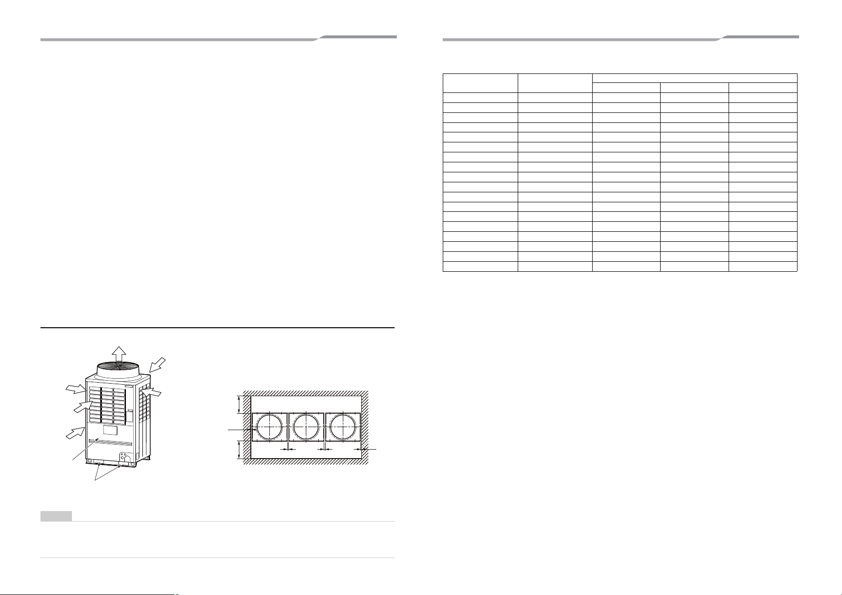
Installation space
Leave space necessary for running, installation and servicing.
NOTE
• If there is an obstacle above the outdoor unit, leave a space of 2000 mm or more to the top end of the outdoor
unit.
• If there is a wall around the outdoor unit, make sure that its height does not exceed 800 mm.
Air discharge
Air
intake
Air intake
Air
intake
Air intake
Installation /
servicing
surface
Square hole for
handling
Outdoor unit top view
10 mm or
more
500 mm or
more
(Rear side)
10 mm or
more
500 mm or
more
(Front side)
20 mm or more
20 mm or more
▼ Combination of outdoor units
Equivalent HP
Model name of
outdoor unit
MMY-
Combination of outdoor unit MMY-
Unit 1Unit 2Unit 3
8 HP MAP0804✽ MAP0804✽ ––
10 HP MAP1004✽ MAP1004✽ ––
12 HP MAP1204✽ MAP1204✽ ––
14 HP MAP1404✽ MAP1404✽ ––
16 HP AP1614✽ MAP0804✽ MAP0804✽ –
18 HP AP1814✽ MAP1004✽ MAP0804✽ –
20 HP AP2014✽ MAP1004✽ MAP1004✽ –
22 HP AP2214✽ MAP1204✽ MAP1004✽ –
24 HP AP2414✽ MAP1404✽ MAP1004✽ –
26 HP AP2614✽ MAP1404✽ MAP1204✽ –
28 HP AP2814✽ MAP1404✽ MAP1404✽ –
30 HP AP3014✽ MAP1004✽ MAP1004✽ MAP1004✽
32 HP AP3214✽ MAP1204✽ MAP1004✽ MAP1004✽
34 HP AP3414✽ MAP1404✽ MAP1004✽ MAP1004✽
36 HP AP3614✽ MAP1204✽ MAP1204✽ MAP1204✽
38 HP AP3814✽ MAP1404✽ MAP1204✽ MAP1204✽
40 HP AP4014✽ MAP1404✽ MAP1404✽ MAP1204✽
42 HP AP4214✽ MAP1404✽ MAP1404✽ MAP1404✽
11-EN 12-EN
–7–
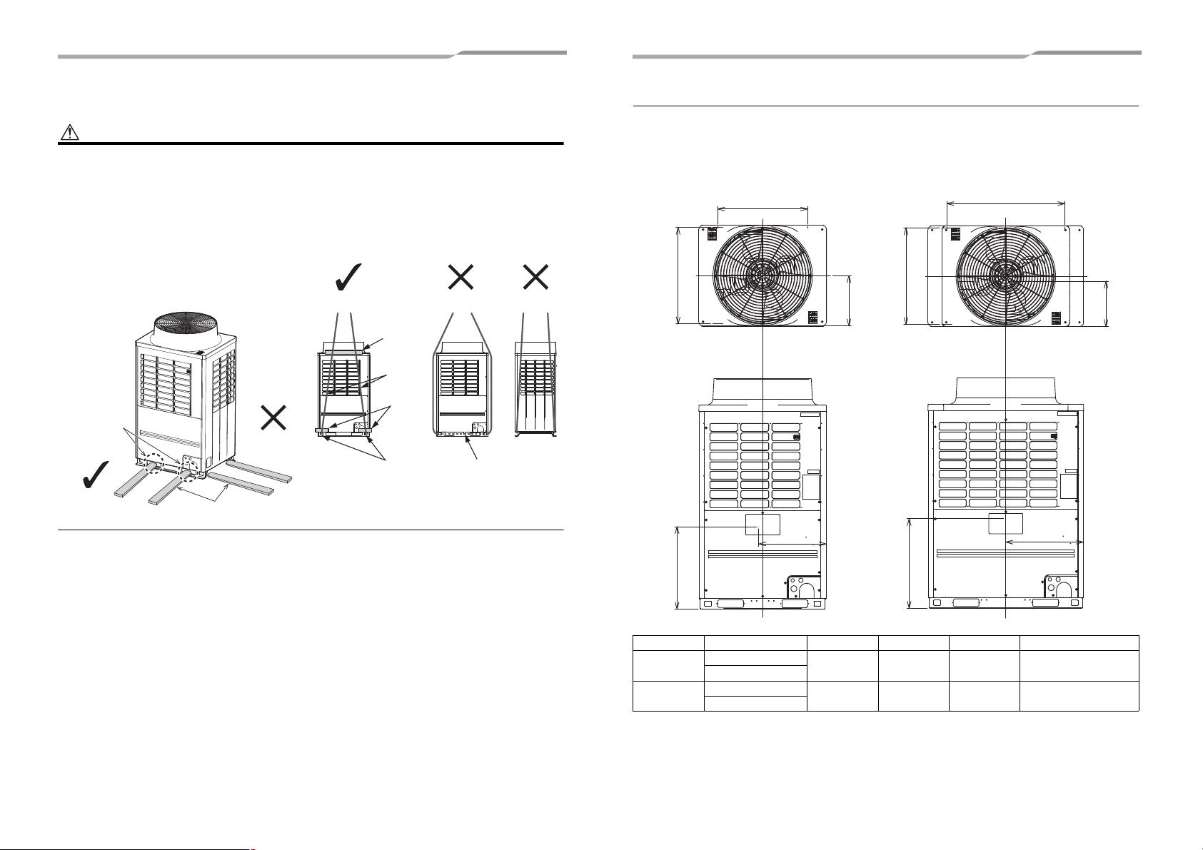
5 Carrying in the outdoor unit
CAUTION
Handle the outdoor unit carefully, observing the following items.
• When using a forklift or other machinery for loading / unloading in transportation, insert the prongs of the forklift
into the rectangular holes for handling as shown below.
• When lifting up the unit, insert a rope able to bear the unit’s weight into the rectangular holes for handling, and
tie the unit from 4 sides.
(Apply padding in positions where the rope comes into contact with the outdoor unit so that no damage is caused
to the outer surface of the outdoor unit.)
(There are reinforcing plates on the side surfaces, so the rope cannot be passed through.)
Front / Back
GOOD NO GOOD NO GOOD
Plaster
Rope
Plaster
Rectangular
holes for
lifting
Reinforcing
plate
Prongs of the
forklift
Rectangular
holes for
handling
GOOD
NO GOOD
Side
Weight centre and weight
◆ Weight centre of an outdoor unit
No. Model type X (mm) Y (mm) Z (mm) Weight (kg)
(A)
MAP080
490 370 680 259
MAP100
(B)
MAP120
590 350 700 334
MAP140
Z
X
Z
X
Y
Y
(A)
(B)
Anchor bolt position
700
Anchor bolt position
920
Anchor bolt position
755
Anchor bolt position
755
13-EN 14-EN
–8–
6 Installation of the outdoor unit
WARNING
• Be sure to install the outdoor unit in a place able to bear its weight.
If strength is insufficient, the unit may fall down resulting in human injury.
• Perform specified installation work to protect against strong wind and earthquakes.
If the outdoor unit is imperfectly installed, an accident by falling or dropping may be caused.
CAUTION
• Drain water is discharged from the outdoor unit. (Especially while heating)
Install the outdoor unit in a place with good drainage.
• For installation, be careful of the strength and level of the foundation so that abnormal sounds (vibration or noise)
are not generated.
REQUIREMENT
Installation in a snowfall area
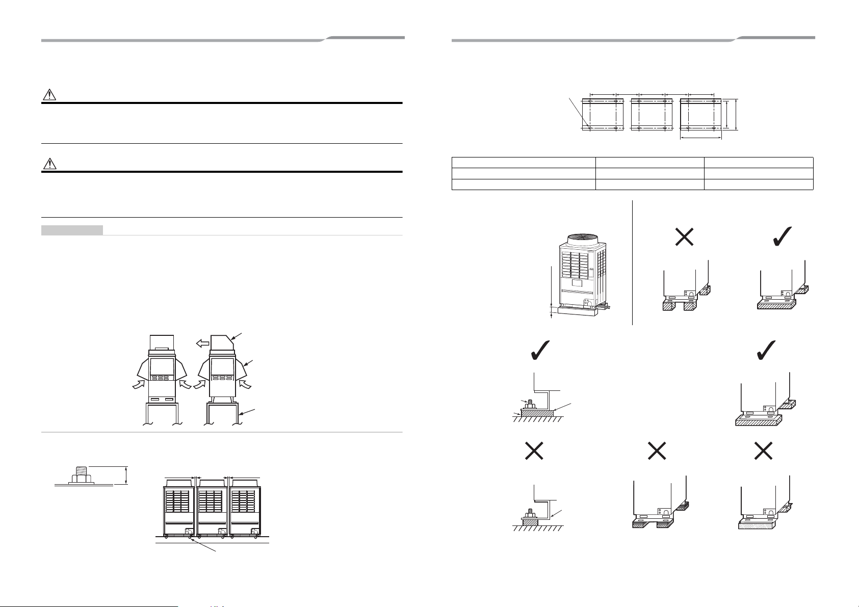
1. Install the outdoor unit on a higher foundation than the snowfall or set up a stand to install the unit so that snowfall
will not affect the unit.
• Set up a stand higher than the snowfall.
• Apply an angled structure to the stand so that drainage will not be prevented. (Avoid using a stand with a flat
surface.)
2. Mount a snowfall-hood onto the air intake and the air discharge.
• Leave enough space for the snowfall-hood so that it will not be an obstacle for the air intake and the air
discharge.
1. To install multiple outdoor units, arrange them with 20 mm or more spaces in between.
Fix each outdoor unit with M12 anchor bolts at 4 positions. 20 mm projection is appropriate for an anchor bolt.
Snowfall-hood for air
discharge
(locally procured)
Snowfall-hood for air
discharge
(4 faces)
(locally procured)
Stand
(locally procured)
20
20 mm or more
20 mm or more
M12 anchor bolt
4 positions / unit
• Anchor bolt positions are as shown below:
(Unit: mm)
4. Mount the vibration-proof rubber (including vibration-proof blocks) so that it fits under the whole clamping leg.
Model type A B
MAP080✽, MAP100✽ 700 990
MAP120✽, MAP140✽ 920 1210
2. When drawing out the refrigerant pipe from the
underside, set the height of the stand to 500 mm or
more.
3. Do not use 4 stands on the corner to support the
outdoor unit.
A A A
B
755
790
Continuous hole
(15 x 20 long hole)
310 or
more
310 or
more
500 mm or more
NO GOOD GOOD
GOOD GOOD
NO GOOD NO GOODNO GOOD
Anchor bolt
Vibration-proof rubber
Install the vibration-proof
rubber so that the bent part
of the fixing leg is
grounded.
The bent part of the
fixing leg is not
grounded.
15-EN 16-EN
–9–
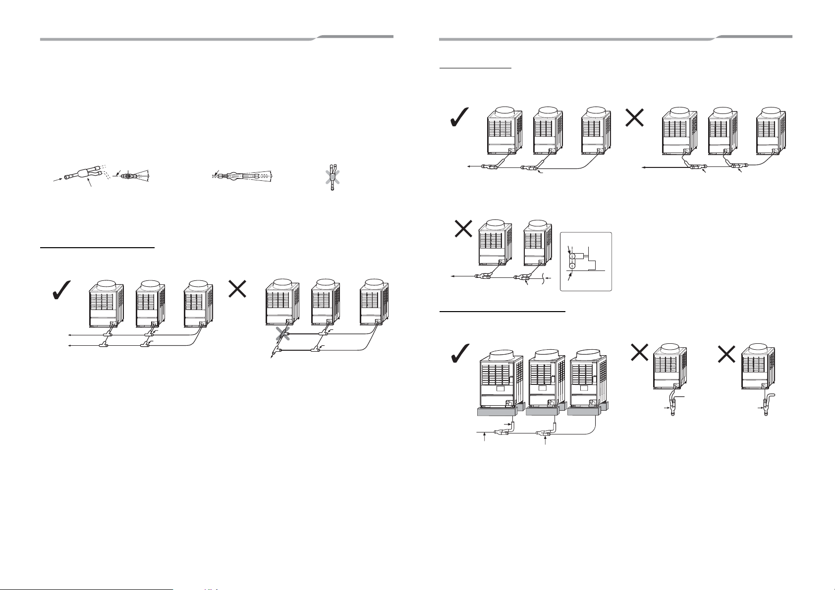
5. Be careful of the connecting arrangement of the header unit and follower units. Set the outdoor units in order of
capacity from the one with the largest capacity. (A (Header unit) ≥ B ≥ C)
1) Be sure to use a header unit for the leading outdoor unit to be connected to the main pipe. (Figure 1, 3 and
5)
2) Be sure to use a T-shaped branch joint (RBM-BT14FE / RBM-BT24FE: separately purchased) to connect
each outdoor unit.
3) When attaching a Y-shaped branch unit for the outdoor unit connection piping kit, attach it level with the
ground (Be sure not to exceed ±15 degrees.). Regarding a T-shape branch joints for the liquid side, there
is no restriction for its angle.
4) Be careful of the direction of the Outdoor unit connection piping kit for the liquid side.
(As shown in Figure 2, a Outdoor unit connection piping kit cannot be attached so that the refrigerant of the
main pipe flows directly into the header unit.)
Discharge gas / Liquid pipes
▼ Figure 1 ▼ Figure 2
A
B
Within ±15 degrees
(Horizontal line)
Within ±15
degrees
(Horizontal line)
(A arrow view)
At a level position
(B arrow view)
Do not connect
a branch unit
vertically.
Header unit A Follower unit B Follower unit C
Main pipe
To indoor unit
Liquid joint
Discharge gas joint
Good
Header unit A Follower unit B Follower unit C
To indoor unit Main pipe
No
Good
Liquid joint
Discharge gas joint
Suction gas pipes
<Suction gas joint reverse orientation installation>
▼ Figure 3 ▼ Figure 4
<Suction gas joint upright orientation installation>
▼ Figure 5
When drawing pipes downward
<Vertical installation> <Vertical installation>
▼ Figure 5 ▼ Figure 6 ▼ Figure 7
Header unit A Follower unit B Follower unit C
Main pipe
Suction gas joint
To indoor unit
Good
Header unit A Follower unit B Follower unit C
Main pipe
Suction gas joint
To indoor unit
No
Good
Suction gas joint
Header unit A Follower unit B
Main pipe
Suction gas joint
To indoor unit
A view
Suction gas joint
A
No
Good
Unit
Vertical line
Header unit
A
Follower unit
B
Follower unit
C
L-shaped
pipe
To gas-side branch
unit
Suction gas joint
Good
Header unit A
Suction gas joint
No
Good
Header unit A
Suction gas joint
No
Good
17-EN 18-EN
–10–
7 Refrigerant piping
WARNING
• If the refrigerant gas leaks during installation, ventilate the room.
If the leaked refrigerant gas comes into contact with fire, noxious gas may be generated.
• After installation, check that the refrigerant gas does not leak.
If the refrigerant gas leaks into the room and comes into contact with fire such as a fan heater, stove, or kitchen range,
noxious gas may be generated.
Connection of refrigerant pipe
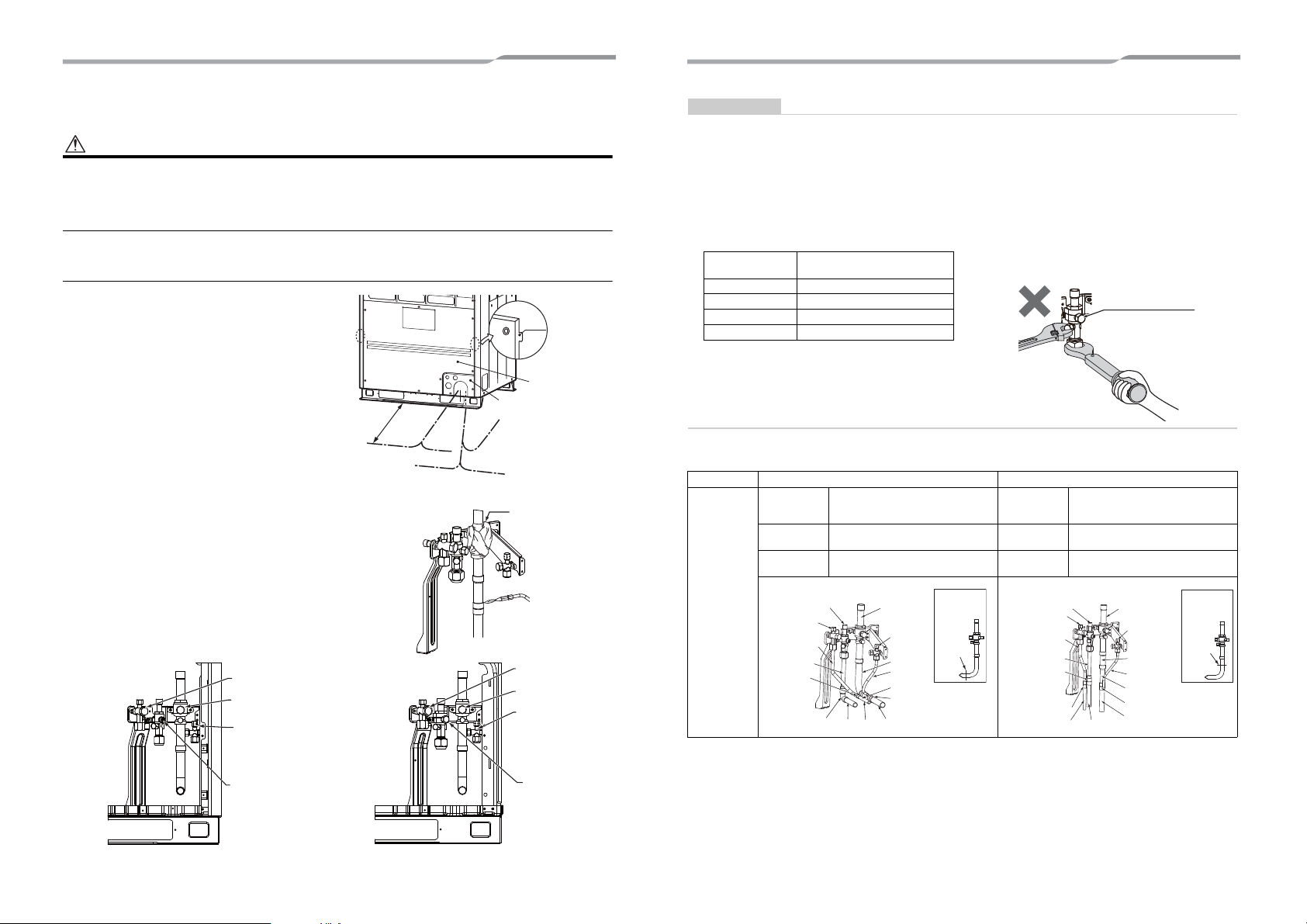
1. The refrigerant pipe connecting section is set in the
outdoor unit. Remove the front panel and the piping /
wiring panel. (M5: 9 pcs.)
• As shown in the illustration on the right, the hooks
are at the right and left sides of the front panel. Lift
up and remove the front panel.
2. Pipes can be drawn out forward or downward from the
outdoor unit.
3. When drawing out the pipe forward, draw it out to the
outside via the piping / wiring panel, and leave a space
of 500 mm or more from the main pipe connecting the
outdoor unit with the indoor unit, considering service
work or other work on the unit. (For replacing the
compressor, 500 mm or more space is required.)
4. When drawing out the pipe downward, remove the
knockouts on the base plate of the outdoor unit, draw
the pipes out of the outdoor unit, and perform piping on
the right / left or rear side. Downward length of the
balance pipe should be 5 m or less.
5. Wrap a wet cloth around the valve of the pipe
connector valve to keep it cool during brazing.
(If it is not cooled enough, the heat may affect the
packing in the valve and cause gas leaks)
(MAP080✽, MAP100✽)(MAP120✽, MAP140✽)
Front panel
Piping / wiring panel
(Rear piping)
Drawing out downward
(Left piping)
(Right piping)
D
r
a
w
i
n
g
o
u
t
f
o
r
w
a
r
d
5
0
0
m
m
o
r
m
o
r
e
Hook
(Left
piping)
(Right
piping)
Wet cloth
Packed valve of
liquid side
Ball valve of suction
gas side
Packed valve of
balance pipe
Ball valve of
discharge gas side
Packed valve of
liquid side
Ball valve of suction
gas side
Packed valve of
balance pipe
Ball valve of
discharge gas side
REQUIREMENT
• For a brazing work of the refrigerant pipes, be sure to use nitrogen gas in order to prevent oxidation of the inside
of the pipes; otherwise clogging of the refrigerating cycle due to oxidized scale may occur.
• Use clean and new pipes for the refrigerant pipes and perform piping work so that water or dust does not
contaminate the refrigerant.
* Remove all flux after brazing.
• Be sure to use a double spanner to loosen or tighten the flare nut. If a single spanner is used, the required level
of tightening cannot be obtained. Tighten the flare nut with the specified torque. (If it is hard to loosen or tighten
the flare nut of the balance pipe or packed valve of the liquid side with a double spanner, loosen or tighten the
flare nut while holding the valve mounting plate with a spanner.)
Pipe connection method of valve at the gas side (Example)
MMY- Draw-out forward Draw-out downward
MAP080✽
MAP100✽
Suction-side
gas pipe
Cut the L-shaped pipe, then braze the
supplied attachment pipe and socket
procured locally.
Suction-side
gas pipe
Cut the L-shaped pipe, then braze the
supplied attachment pipe and socket
procured locally.
Discharge-
side gas pipe
Braze the supplied attachment pipe
and elbow procured locally.
Discharge-
side gas pipe
Braze the supplied attachment pipe
and socket procured locally.
Liquid pipe
Braze the supplied attachment pipe
and socket procured locally.
Liquid pipe
Braze the supplied attachment pipe
and socket procured locally.
Outer dia. of
copper pipe
Tightening torque (N•m)
9.5 mm 34 to 42
12.7 mm 49 to 61
15.9 mm 63 to 77
19.1 mm 100 to 120
Ball valve of discharge
gas side
Do not clamp the
service port with a
double spanner, doing
so may damage the
service port.
Do not apply refrigerating oil to the
surface of the flare.
Discharge-
side gas pipe
Liquid pipe
L-shaped
pipe
Balance
pipe
Suction-side
gas pipe
Section
to be
cut
Attachment
pipe
Pipe
Socket
PipePipePipe
Attachment
pipe
Attachment
pipe
Socket
Elbow
Suction-side
gas pipe
Discharge-
side gas pipe
Liquid pipe
L-shaped
pipe
Suction-side
gas pipe
Suction-side
gas pipe
Section
to be
cut
Pipe
Socket
Pipe
Pipe
Attachment
pipe
Attachment
pipe
Socket
Pipe
Attachment
pipe
Socket
Balance
pipe
19-EN 20-EN
–11–
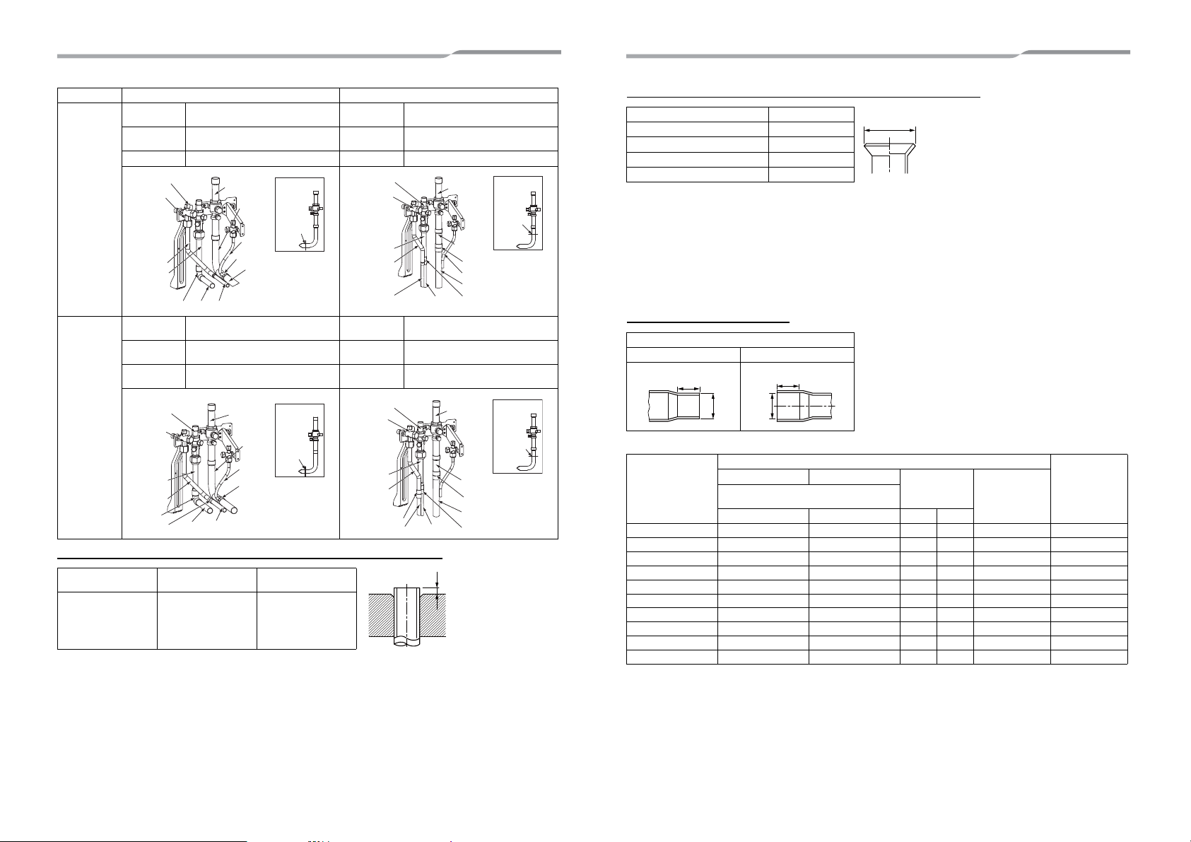
Extruding margin of copper pipe with flare machining: B (Unit: mm)
MAP120✽
Suction-side
gas pipe
Cut the L-shaped pipe, then braze the
socket procured locally.
Suction-side
gas pipe
Cut the L-shaped pipe, then braze the
socket procured locally.
Discharge-
side gas pipe
Braze the supplied attachment pipe
and elbow procured locally.
Discharge-
side gas pipe
Braze the supplied attachment pipe
and socket procured locally.
Liquid pipe Braze the supplied attachment pipe. Liquid pipe Braze the supplied attachment pipe.
MAP140✽
Suction-side
gas pipe
Cut the L-shaped pipe, then braze the
socket procured locally.
Suction-side
gas pipe
Cut the L-shaped pipe, then braze the
socket procured locally.
Discharge-
side gas pipe
Braze the supplied attachment pipe
and elbow procured locally.
Discharge-
side gas pipe
Braze the supplied attachment pipe
and socket procured locally.
Liquid pipe
Braze the supplied attachment pipe
and socket procured locally.
Liquid pipe
Braze the supplied attachment pipe
and socket procured locally.
Copper pipe outer
dia.
When using R410A
tool
When using
conventional tool
9.5
12.7
15.9
19.1
0 to 0.5 1.0 to 1.5
MMY- Draw-out forward Draw-out downward
Discharge-
side gas pipe
Liquid pipe
Suction-side
gas pipe
Suction-side
gas pipe
Section to
be cut
L-shaped
pipe
Pipe
Socket
Pipe
PipePipe
Attachment
pipe
Attachment
pipe
Elbow
Discharge-
side gas pipe
Liquid pipe
Suction-side
gas pipe
Suction-side
gas pipe
Section to
be cut
L-shaped
pipe
Pipe
Socket
Pipe
Pipe
Attachment
pipe
Attachment
pipe
Pipe
Socket
Discharge-
side gas pipe
Liquid pipe
Suction-side
gas pipe
Suction-side
gas pipe
Section to
be cut
L-shaped
pipe
Socket
Pipe
Attachment
pipe
Attachment
pipe
Elbow
Socket
Pipe
Pipe
Discharge-
side gas pipe
Liquid pipe
Suction-side
gas pipe
Suction-side
gas pipe
Section to
be cut
L-shaped
pipe
Socket
Pipe
Pipe
Attachment
pipe
Attachment
pipe
Pipe
Socket
Socket
B
Extruding margin of copper pipe with flare tools: A (Unit: mm)
• When using the conventional flare tool, to connect R410A pipes with flaring, make a margin approx. 0.5 mm
longer than that of an R22 pipe so that the flare size matches the one specified. It is convenient to use a copper
pipe gauge for size adjustment of the extruding margin.
• The flared supplied attachment pipe (Ø19.1) must be used to connect with discharge-side gas pipe (Ø19.1) of
MAP120 and MAP140. Do not use half hard or hard materials instead of the supplied attachment pipe. The half
hard or hard materials may be cracked and may cause leakage of refrigerant when it is flared.
• Use the flare nut provided with the product.
• After flaring the connection, be sure the flared part is not damaged, deformed, uneven, or flattened, and that
there are no cutting chips on it.
Coupling size of brazed pipe
(Unit: mm)
Copper pipe outer dia. A
9.5 13.2
12.7 16.6
15.9 19.7
19.1 24.0
Connected section
External size Internal size
Standard outer dia.
of connected
copper pipe
Connected section
Min. thickness
of coupling
External size Internal size
Min. depth of
insertion
Oval value
Standard outer dia.
(Allowable difference)
CFKG
6.35 6.35 (±0.03) 6.45 ( ) 7 6 0.06 or less 0.50
9.52 9.52 (±0.03) 9.62 ( ) 8 7 0.08 or less 0.60
12.70 12.70 (±0.03) 12.81 ( ) 9 8 0.10 or less 0.70
15.88 15.88 (±0.03) 16.00 ( ) 9 8 0.13 or less 0.80
19.05 19.05 (±0.03) 19.19 ( ) 11 10 0.15 or less 0.80
22.22 22.22 (±0.03) 22.36 ( ) 11 10 0.16 or less 0.82
28.58 28.58 (±0.04) 28.75 ( ) 13 12 0.20 or less 1.00
34.92 34.90 (±0.04) 35.11 ( ) 14 13 0.25 or less 1.20
38.10 38.10 (±0.05) 38.31 ( ) 15 14 0.27 or less 1.26
41.28 41.28 (±0.05) 41.50 ( ) 15 14 0.28 or less 1.35
+0
-0.4
A
K
ØC
G
ØF
+0.04
-0.02
+0.04
-0.02
+0.04
-0.02
+0.04
-0.02
+0.03
-0.03
+0.03
-0.03
+0.06
-0.02
+0.04
-0.04
+0.08
-0.02
+0.08
-0.02
21-EN 22-EN
 Loading...