


INSTALLATION MANUAL MANUEL D’INSTALLATION INSTALLATIONS-HANDBUCH MANUALE DI INSTALLAZIONE MANUAL DE INSTALACIÓN MANUAL DE INSTALAÇÃO INSTALLATIEHANDLEIDING
ЕГЧЕЙСЙДЙП ЕГКБФБУФБУЗУ
SUPER MODULAR MULTI SYSTEM AIR CONDITIONER
SMMS CLIMATISEUR
SMMS KLIMAGERÄ T
SMMS CONDIZIONATORE D'ARIA
SMMS APARATO DE AIRE ACONDICIONADO
SMMS AR CONDICIONADO
SMMS AIRCONDITIONER
SMMS КЛЙМБФЙУФЙКП
SMMS
Indoor Unit Unité intérieure Raumeinheit Unità interna Unidad interior Unidade interior Binnenunit
ЕущфесйкЮ mпнЬдб
For commercial use (Not accessible to the general public) Pour usage commercial (Vente interdite au grand public)
Nur fü r gewerbliche Nutzung (kein öffentlicher Zugang)
Per uso commerciale (Non accessibile a clienti generici) Para uso comercial (no destinado al público en general) Para uso comercial (não acessível ao público em geral)
Voor commercieel gebruik (niet geschikt voor huishoudelijk gebruik)
Гйб емрпсйкЮ чсЮуз (Мз дйбиЭуймп уфп ехсэ кпйнь)
<1-way Air Discharge Cassette Type> |
<Ceiling Panel> |
<Type cassette à 1 voies de soufflage> |
<Panneau pour plafond> |
<1-Wege-Belüftungskassette> |
<Deckenkassette> |
<Tipo a cassetta con scarico d'aria a 1 vie> |
<Pannello al soffitto> |
<Modelo de casete de distribución de aire de 1 vías> |
<Panel del techo> |
<Descarga de ar tipo cassete de 1 vias> |
<Painel de tecto> |
<Model voor inbouw in plafond met 1 uitblaasopeningen> |
<Plafondpaneel> |
<ЕкспЮ бЭсб 1-Дйехиэнуещн Фэрпх КбуЭфбт> |
<ЦЬфнщмб пспцЮт> |
MMU-AP0071YH, |
RBC-UY135PG |
MMU-AP0091YH, |
|
MMU-AP0121YH |
|

ADOPTION OF NEW REFRIGERANT
This Air Conditioner is a new type which adopts a new refrigerant HFC (R410A) instead of the conventional refrigerant R22 in order to prevent destruction of the ozone layer.
Thank you very much for purchasing TOSHIBA Air Conditioner.
Please read this owner's manual carefully before using your Air
Conditioner.
•Be sure to obtain the “Owner’s manual” and “Installation manual” from constructor (or dealer).
Request to constructor or dealer
Please clearly explain the contents of the Owner’s manual and hand over it.
UTILISATION DU NOUVEAU REFRIGERANT
Ce climatiseur est d’un type inédit qui utilise le nouveau réfrigérant HFC (R410A) au lieu du réfrigérant traditionnel R22, afin d’éviter la destruction de la couche d’ozone.
Nous vous remercions pour avoir choisi un climatiseur TOSHIBA.
Veuillez lire attentivement ce Manuel du propriétaire avant d’utiliser votre climatiseur.
•Assurez-vous que le constructeur (ou le revendeur) vous remette le “Manuel du propriétaire” et le “Manuel d’installation”.
Demande au constructeur ou au revendeur
Veuillez expliquer clairement le contenu du Manuel du propriétaire et le remettre au client.
EINFÜ HRUNG EINES NEUEN KÜ HLMITTELS
Dies ist ein neuartiges Klimagerät. Anstatt des herkömmlichen Kühlmittels R22 verwendet es das neue ozonschicht-schonende HFC Kühlmittel R410A.
Wir danken Ihnen, dass Sie sich für ein TOSHIBA Klimagerät entschieden haben.
Bitte lesen Sie diese Betriebsanleitung, bevor Sie Ihr Klimagerät benutzen, sorgfältig.
•Lassen Sie sich die “Betriebsanleitung” und das “Installations-Handbuch” unbedingt vom Installateur oder vom Lieferanten aushändigen.
Eine Bitte an den Installateur oder Lieferanten:
Bitte erklären Sie dem Käufer den Inhalt der Betriebsanleitung und händigen sie ihm aus.
ADOZIONE DI UN NUOVO REFRIGERANTE
Questo condizionatore d'ariaè di un tipo nuovo che adotta un nuovo refrigerate HFC (R410A) al posto del refrigerante convenzionale R22, per prevenire la distruzione dello strato di ozono dell'atmosfera terrestre.
Grazie di aver acquistato un condizionatore d'aria TOSHIBA.
Prima di usare il condizionatore d'aria, leggere con attenzione questo manuale del proprietario.
•Si raccomanda di tenere a portata di mano il “Manuale del proprietario” e il “Manuale di installazione” ricevuti dal produttore (o dal rivenditore).
Richiesta al produttore o al rivenditore
Spiegare chiaramente il contenuto del Manuale del proprietario e consegnarne una copia all'utente.
ADOPCIÓ N DE NUEVO REFRIGERANTE
Este aparato de aire acondicionado es un modelo reciente que incorpora el nuevo refrigerante HFC (R410A) en lugar del refrigerante convencional R22 para asíevitar daños en la capa de ozono.
Muchas gracias por haber adquirido el aparato de aire acondicionado TOSHIBA. Lea atentamente este manual del propietario antes de utilizar el aparato de aire acondicionado.
•Asegúrese de que el fabricante (o distribuidor) le proporcione el “Manual del propietario” y el “Manual de instalación”.
Solicitud al fabricante o distribuidor
Explique con claridad el contenido del Manual del propietario y entréguelo al cliente.
ADOPÇÃ O DO NOVO REFRIGERANTE
Este ar condicionado é um modelo novo que adopta um novo refrigerante HFC (R410A) em vez do refrigerante convencional R22 para evitar a destruição da cama de ozono.
Muito obrigada por adquirir o Ar Condicionado TOSHIBA.
Leia atentamente este manual do utilizador antes de utilizar o seu ar condicionado.
•Não se esqueça de receber o “Manual do utilizador” e o “Manual de inslatação” do fabricante (ou agente).
Pedido ao fabricante ou agente
Explique por favor o conteúdo do Manual do utilizador e entregue-o.
TOEPASSING VAN EEN NIEUW KOELMIDDEL
Deze airconditioner is een nieuwe type dat werkt met een nieuw koelmiddel HFC (R410A) in plaats van met het conventionele koelmiddel R22, als bijdrage om de aantasting van de ozonlaag te reduceren.
Hartelijk dank voor uw keuze voor een airconditioner van TOSHIBA.
Lees deze gebruiksaanwijzing zorgvuldig door voordat u de airconditioner gaat gebruiken.
•Zorg ervoor dat u zowel de ‘gebruiksaanwijzing’ als de ‘installatiehandleiding’ van de installateur (of leverancier) krijgt.
Verzoek aan de installateur of de leverancier
Leg de inhoud van de gebruiksaanwijzing duidelijk uit en overhandig de gebruiksaanwijzing nadien aan de klant.
ХЙПИЕФЗУЗ НЕПХ ШХКФЙКПХ |
Убт ехчбсйуфпэме рплэ рпх рспфймЮубфе гйб фзн бгпсЬ убт Энб |
|
Клймбфйуфйкь TOSHIBA. |
||
Фп рбсьн Клймбфйуфйкь еЯнбй нЭпт фэрпт рпх хйпиефеЯ нЭп |
Рбсбкблпэме дйбвЬуфе рспуечфйкЬ фйт пдзгЯет чсЮузт рсйн брь фз чсЮуз |
|
фпх Клймбфйуфйкпэ. |
||
шхкфйкь HFC (R410A) уфз иЭуз фпх ухмвбфйкпэ |
• ВевбйщиеЯфе ьфй п кбфбукехбуфЮт (Ю п рщлзфЮт) убт рбсЭдщуе кбй фйт |
|
шхкфйкпэ R22 рспкеймЭнпх нб впзиЮуей уфзн рспуфбуЯб |
“ПдзгЯет ЧсЮузт” кбй фп “ЕгчейсЯдйп ЕгкбфЬуфбузт”. |
|
фпх ьжпнфпт. |
РбсЬклзуз гйб фпн кбфбукехбуфЮ Ю фпн рщлзфЮ |
|
Рбсбкблю еозгЮуфе ме убцЮнейб фб ресйечьменб фщн Пдзгйюн ЧсЮузт кбй |
||
|
||
|
рбсбдюуфе фп. |
|
|
|


 HFC
HFC
 R410A
R410A


 R22
R22

|
CONTENTS |
|
ENGLISH |
||||
Accessory parts and Parts to be procured locally ........................... |
1 |
6 |
ELECTRIC WORK ....................................................................... |
13 |
|||
1 |
PRECAUTIONS FOR SAFETY ..................................................... |
2 |
7 |
APPLICABLE CONTROLS ......................................................... |
17 |
||
2 |
SELECTION OF INSTALLATION PLACE ..................................... |
4 |
8 |
TEST RUN ................................................................................... |
19 |
||
3 |
INSTALLATION OF INDOOR UNIT ............................................... |
5 |
9 |
TROUBLESHOOTING ................................................................. |
21 |
||
4 |
DRAIN PIPING WORK |
9 |
10 |
MAINTENANCE |
26 |
||
|
|||||||
5 |
REFRIGERANT PIPING .............................................................. |
11 |
|
|
|
|
|
|
SOMMAIRE |
|
FRANCAIS |
||||
Piè ces accessoires et piè ces non fournies ..................................... |
27 |
6 |
TRAVAUX D’É LECTRICITÉ |
39 |
|||
1 |
MESURES DE SECURITE |
28 |
|||||
7 |
COMMANDES UTILISABLES |
43 |
|||||
2 |
SELECTION DU LIEU D’INSTALLATION |
30 |
|||||
8 |
ESSAI DE FONCTIONNEMENT |
45 |
|||||
3 |
INSTALLATION DE L’UNITE INTERIEURE |
31 |
|||||
9 |
DÉ PANNAGE |
47 |
|||||
4 |
INSTALLATION DES TUYAUX D’EVACUATION ......................... |
35 |
|||||
5 |
TUYAUX DE RÉ FRIGÉ RANT |
37 |
10 |
ENTRETIEN ................................................................................. |
52 |
|
|
|
|
|
|
||||
|
|
|
|
|
|
||
|
|
INHALT |
|
|
DEUTSCH |
||
Zubehö r und bauseits bereitzustellende Teile ................................. |
53 |
6 |
ELEKTROARBEITEN |
65 |
|||
1 |
SICHERHEITSVORKEHRUNGEN |
54 |
|||||
7 |
STEUERUNGSMÖ GLICHKEITEN |
69 |
|||||
2 |
AUSWAHL DES AUFSTELLUNGSORTES |
56 |
|||||
8 |
TESTLAUF |
71 |
|||||
3 |
INSTALLATION DER RAUMEINHEIT |
57 |
|||||
9 |
FEHLERSUCHE |
73 |
|||||
4 |
INSTALLATION DES KONDENSWASSER-ABLAUFS ............... |
61 |
|||||
5 |
KÜ HLMITTELLEITUNGEN |
63 |
10 |
WARTUNG ................................................................................... |
78 |
|
|
|
|
|
|
||||
|
|
|
|
|
|
||
|
|
INDICE |
|
|
ITALIANO |
||
Accessori e parti da acquistare sul posto ....................................... |
79 |
6 |
COLLEGAMENTI ELETTRICI |
91 |
|||
1 |
PRECAUZIONI PER LA SICUREZZA |
80 |
|||||
7 |
COMANDI APPLICABILI |
95 |
|||||
2 |
SCELTA DEL POSTO D’INSTALLAZIONE |
82 |
|||||
8 |
FUNZIONAMENTO DI PROVA |
97 |
|||||
3 |
INSTALLAZIONE DELL’UNITÀ INTERNA |
83 |
|||||
9 |
RISOLUZIONE DEI PROBLEMI |
99 |
|||||
4 |
|
|
|||||
LAVORO PER TUBAZIONE DI SCARICO |
87 |
10 |
MANUTENZIONE |
104 |
|||
|
|||||||
5 |
TUBAZIONI DEL REFRIGERANTE |
89 |
|
||||
|
|
|
|
||||
|
CONTENIDO |
|
OL |
||||
Componentes accesorios y componentes de suministro local .. |
105 |
6 |
INSTALACIÓ N ELÉ CTRICA |
117 |
|||
1 |
PRECAUCIONES PARA SU SEGURIDAD |
106 |
|||||
7 |
CONTROLES APLICABLES |
121 |
ESPAÑ |
||||
2 |
SELECCIÓ N DEL LUGAR DE INSTALACIÓ N |
108 |
|||||
8 |
PRUEBA DE FUNCIONAMIENTO |
123 |
|||||
3 |
INSTALACIÓ N DE LA UNIDAD INTERIOR |
109 |
|||||
9 |
RESOLUCIÓ N DE PROBLEMAS |
125 |
|||||
4 |
CANALIZACIÓ N DE DRENAJE ................................................ |
113 |
|||||
5 |
TUBERÍA DE REGRIGERANTE |
115 |
10 |
MANTENIMIENTO ..................................................................... |
130 |
|
|
|
|
|
|
||||
|
|
|
|
|
|
||
|
|
ÍNDICE |
|
|
S |
||
Acessó rios e peç as adquiridas localmente .................................. |
131 |
6 |
TRABALHOS DE ELECTRICIDADE |
143 |
PORTUGUÊ |
||
1 |
PRECAUÇÕ ES DE SEGURANÇ A |
132 |
|||||
7 |
CONTROLOS APLICÁ VEIS |
147 |
|||||
2 |
SELECÇÃ O DO LOCAL DE INSTALAÇÃ O |
134 |
|||||
8 |
TESTE DE FUNCIONAMENTO |
149 |
|||||
3 |
INSTALAÇÃ O DA UNIDADE INTERIOR |
135 |
|||||
9 |
RESOLUÇÃ O DE PROBLEMAS |
151 |
|||||
4 |
INSTALAÇÃ O DA TUBAGEM DE DRENAGEM |
139 |
|||||
10 |
MANUTENÇÃ O |
156 |
|||||
5 |
TUBAGEM DE REFRIGERANTE |
141 |
|||||
|
|
|
|
||||
|
|
INHOUD |
|
|
NEDERLANDS |
||
Accessoires en niet meegeleverde onderdelen ............................ |
157 |
6 |
ELEKTRISCHE BEDRADING |
169 |
|||
1 |
VOORZORGSMAATREGELEN VOOR UW VEILIGHEID |
158 |
|||||
7 |
BEDIENINGSELEMENTEN |
173 |
|||||
2 |
KEUZE VAN DE LOCATIE VOOR DE INSTALLATIE |
160 |
|||||
8 |
WERKINGSTEST |
175 |
|||||
3 |
INSTALLATIE VAN DE BINNENUNIT |
161 |
|||||
9 |
STORINGEN VERHELPEN |
177 |
|||||
4 |
AFVOERLEIDINGEN |
165 |
|||||
10 |
ONDERHOUD |
182 |
|||||
5 |
KOELMIDDELLEIDINGEN ........................................................ |
167 |
|||||
|
РЕСЙЕЧПМЕНБ |
|
ЕЛЛЗНЙКБ |
||||
Рбселкьменб бнфбллбкфйкЬ кбй ЕобсфЮмбфб брь фзн фпрйкЮ бгпсЬ .... |
183 |
6 |
ЗЛЕКФСЙКЗ ЕСГБУЙБ |
195 |
|||
1 |
РСПЦХЛБОЕЙУ БУЦБЛЕЙБУ |
184 |
|||||
7 |
ЕЦБСМПУЙМПЙ ЕЛЕГЧПЙ |
199 |
|||||
2 |
ЕРЙЛПГЗ ФПХ ЧЩСПХ ЕГКБФБУФБУЗУ |
186 |
|||||
8 |
ДПКЙМЗ ЛЕЙФПХСГЙБУ |
201 |
|||||
3 |
ЕГКБФБУФБУЗ ФЗУ ЕУЩФЕСЙКЗУ МПНБДБУ |
187 |
|||||
9 |
БНФЙМЕФЩРЙУЗ РСПВЛЗМБФЩН |
203 |
|||||
4 |
ЕГКБФБУФБУЗ УЩЛЗНЩУЕЩН БРПУФСБГГЙУЗУ |
191 |
|||||
10 |
УХНФЗСЗУЗ |
208 |
|||||
5 |
УЩЛЗНЩУЗ ШХКФЙКПХ МЕУПХ |
193 |
|
||||
|
|
|
|
||||
|
|
|
|
|
|
|
|
1 |
|
209 |
6 |
|
221 |
|
|
|
210 |
|
|
||||
|
7 |
|
225 |
|
|||
2 |
|
212 |
|
|
|||
|
8 |
|
227 |
|
|||
3 |
|
213 |
|
|
|||
|
9 |
|
229 |
|
|||
4 |
|
217 |
|
|
|||
|
10 |
|
234 |
|
|||
5 |
|
219 |
|
|
|||
|
|
|
|
|
|||
|
|
|
|
|
|
|
|
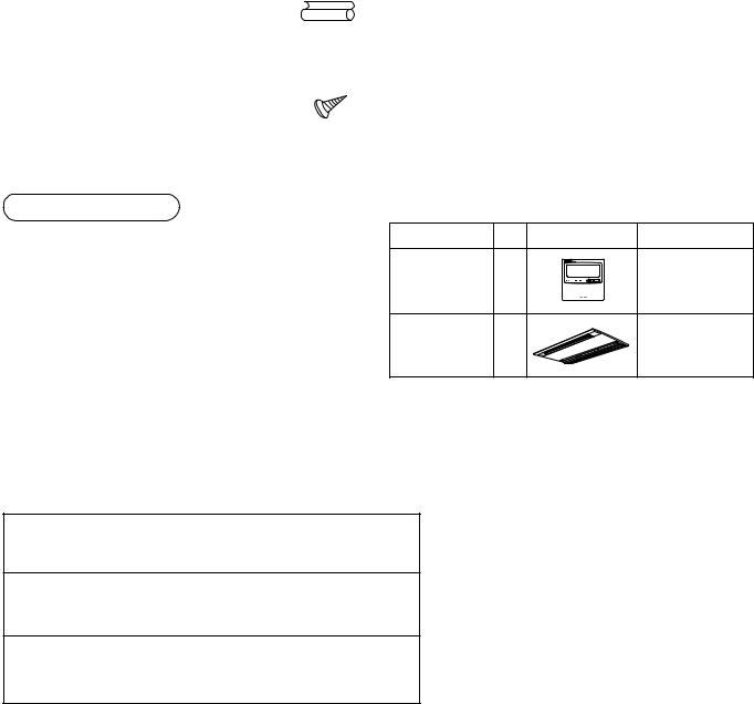
Accessory parts and Parts to be procured locally
H Accessory parts
Part name |
Q’ty |
Shape |
Usage |
|
|
|
|
Installation Manual |
1 |
This manual |
(Be sure to hand over customers) |
|
|
|
|
Heat Insulating pipe |
2 |
|
For heat insulating of pipe connecting section |
|
|
|
|
Installation pattern |
1 |
— |
For confirmation of ceiling opening and main unit position |
|
|
|
|
Pattern fixing screw |
5 |
|
Installation pattern fixing |
|
|
|
|
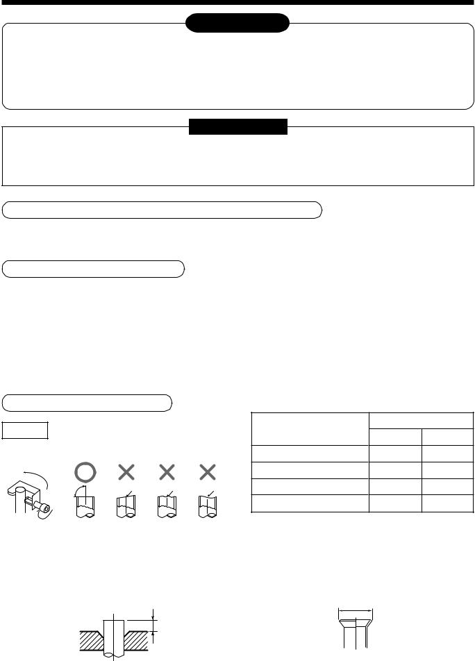
Refrigerant piping
•Piping material used for the conventional refrigerant cannot be used.
•Use copper pipe with 0.8 mm or more thickness for Ø6.4, Ø9.5, Ø12.7.
•Flare nut and flare works are also different from those of the conventional refrigerant. Take out the flare nut attached to the indoor unit of the air conditioner, and use it.
<Separate sold parts>
Part name |
Q’ty |
Shape |
Usage |
Standard wired |
1 |
|
Model |
remote controller |
|
RBC-AMT21E |
|
|
|
||
Ceiling panel |
1 |
|
Model |
|
RBC-UY135PG |
||
|
|
|
H Parts to be procured locally
Connecting pipe (Liquid side)
(6.4mm (diam.), Nominal (diam.) 1/4” thick 0.8mm)
Connecting pipe (Gas side)
(12.7mm (diam.), Nominal (diam.) 3/8” thick 0.8mm)
Power supply cord
Cable 3-core 2.5mm2, in conformity with Design 60245 IEC57
1
1 PRECAUTIONS FOR SAFETY
•Ensure that all Local, National and International regulations are satisfied.
•Read this “PRECAUTIONS FOR SAFETY” carefully before Installation.
•The precautions described below include the important items regarding safety. Observe them without fail.
•After the installation work, perform a trial operation to check for any problem.
Follow the Owner’s Manual to explain how to use and maintain the unit to the customer.
•Turn off the main power supply switch (or breaker) before the unit maintenance.
•Ask the customer to keep the Installation Manual together with the Owner’s Manual.
CAUTION New Refrigerant Air Conditioner Installation
•THIS AIR CONDITIONER ADOPTS THE NEW HFC REFRIGERANT (R410A) WHICH DOES NOT DESTROY OZONE LAYER.
The characteristics of R410A refrigerant are ; easy to absorb water, oxidizing membrane or oil, and its pressure is approx. 1.6 times higher than that of refrigerant R22. Accompanied with the new refrigerant, refrigerating oil has also been changed. Therefore, during installation work, be sure that water, dust, former refrigerant, or refrigerating oil does not enter the refrigerating cycle.
To prevent charging an incorrect refrigerant and refrigerating oil, the sizes of connecting sections of charging port of the main unit and installation tools are charged from those for the conventional refrigerant.
Accordingly the exclusive tools are required for the new refrigerant (R410A).
For connecting pipes, use new and clean piping designed for R410A, and please care so that water or dust does not enter. Moreover, do not use the existing piping because there are problems with pressure-resistance force and impurity in it.
ENGLISH
CAUTION To Disconnect the Appliance from Main Power Supply.
This appliance must be connected to the main power supply by means of a switch with a contact separation of at least 3 mm.
 WARNING
•Ask an authorized dealer or qualified installation professional to install/maintain the air conditioner.
Inappropriate installation may result in water leakage, electric shock or fire.
•Turn off the main power supply switch or breaker before attempting any electrical work.
Make sure all power switches are off. Failure to do so may cause electric shock.
•Connect the connecting wire correctly.
If the connecting wire is connected in a wrong way, electric parts may be damaged.
•When moving the air conditioner for the installation into another place, be very careful not to enter any gaseous matter other than the specified refrigerant into the refrigeration cycle.
If air or any other gas is mixed in the refrigerant, the gas pressure in the refrigeration cycle becomes abnormally high and it resultingly causes pipe burst and injuries on persons.
•Do not modify this unit by removing any of the safety guards or by by-passing any of the safety interlock switches.
•Exposure of unit to water or other moisture before installation may cause a short-circuit of electrical parts.
Do not store it in a wet basement or expose to rain or water.
2

1 PRECAUTIONS FOR SAFETY
•After unpacking the unit, examine it carefully if there are possible damage.
•Do not install in a place that might increase the vibration of the unit.
•To avoid personal injury (with sharp edges), be careful when handling parts.
•Perform installation work properly according to the Installation Manual.
Inappropriate installation may result in water leakage, electric shock or fire.
•When the air conditioner is installed in a small room, provide appropriate measures to ensure that the concentration of refrigerant leakage occur in the room does not exceed the critical level.
•Install the air conditioner securely in a location where the base can sustain the weight adequately.
•Perform the specified installation work to guard against an earthquake.
If the air conditioner is not installed appropriately, accidents may occur due to the falling unit.
•If refrigerant gas has leaked during the installation work, ventilate the room immediately.
If the leaked refrigerant gas comes in contact with fire, noxious gas may generate.
•After the installation work, confirm that refrigerant gas does not leak.
If refrigerant gas leaks into the room and flows near a fire source, such as a cooking range, noxious gas might generate.
•Electrical work must be performed by a qualified electrician in accordance with the Installation Manual. Make sure the air conditioner uses an exclusive power supply.
An insufficient power supply capacity or inappropriate installation may cause fire.
•Use the specified wires for wiring connect the terminals securely fix. To prevent external forces applied to the terminals from affecting the terminals.
•Conform to the regulations of the local electric company when wiring the power supply.
Inappropriate grounding may cause electric shock.
•Do not install the air conditioner in a location subject to a risk of exposure to a combustible gas.
If a combustible gas leaks, and stays around the unit, a fire may occur.
3
2 SELECTION OF INSTALLATION PLACE
 WARNING
•Install the air conditioner at enough strong place to withstand the weight of the unit.
If the strength is not enough, the unit may fall down resulting in injury.
•Perform a specified installation work to guard against an earth quake.
An incomplete installation can cause accidents by the units failing and dropping.
•Install the air conditioner at a height 2.5m or more from the floor.
If you insert your hands or others directly into the unit while the air conditioner operates, it is dangerous because you may contact with revolving fan or active electricity.
 CAUTION
•Do not install the air conditioner in a location subject to a risk of exposure to combustible gas.
Should the combustible gas leak and collect near the unit, fire may occur.
Upon approval of the customer, install the air conditioner in a place that satisfies the following conditions.
•Place where the unit can be installed horizontally.
•Place where a sufficient servicing space can be ensured for safe maintenance and check.
•Place where drained water will not cause any problem.
Avoid installing in the following places.
•Place exposed to air with high salt content (seaside area), or place exposed to large quantities of sulfide gas (hot spring). (Should the unit be used in these places, special protective measures are needed.)
•Place exposed to oil, vapor, oil smoke or corrosive gas.
•Place where organic solvent is used nearby.
•Place close to a machine generating high frequency.
•Place where the discharged air blows directly into the window of the neighboring house. (For outdoor unit)
•Place where noise of the outdoor unit is easily transmitted.
(When installing the air conditioner on the boundary with the neighbor, pay due attention to the level of noise.)
•Place with poor ventilation.
Installation space
Reserve space required to install the indoor unit and for service work.
|
|
|
|
|
|
Ceiling inside height : |
|
|
|||||||
Refrigerant piping port |
|
245mm or more |
|
|
|||||||||||
|
|
|
|
|
|
|
|
|
|
|
|
|
|
|
|
|
|
|
|
|
|
|
|
|
|
|
|
|
|
|
|
|
|
|
|
|
|
|
|
|
|
|
|
|
|
|
|
|
|
|
|
|
|
|
|
|
|
|
|
|
|
|
|
|
|
|
|
|
|
|
|
|
|
|
|
|
|
|
|
|
|
|
|
|
|
|
|
|
|
|
|
|
|
|
|
|
|
|
|
|
|
|
|
|
|
|
|
|
|
|
|
|
|
|
|
|
|
|
|
|
|
|
|
|
|
|
|
100mm |
100mm |
Ceiling |
200mm |
||
and more |
and more |
or more |
The lighting term setup of the filter sign (Notification of filter cleaning) of the remote controller can be changed according to the condition of installation. If the room is not heated due to the installation place or construction of the room, the detection temperature of heating can be raised.
For setup method, refer to “Change of lighting term of filter sign” and “To secure better effect of heating” in the Applicable controls of this Manual.
4
2 SELECTION OF INSTALLATION PLACE
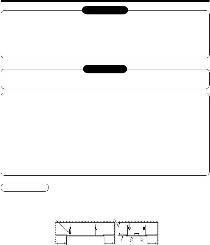
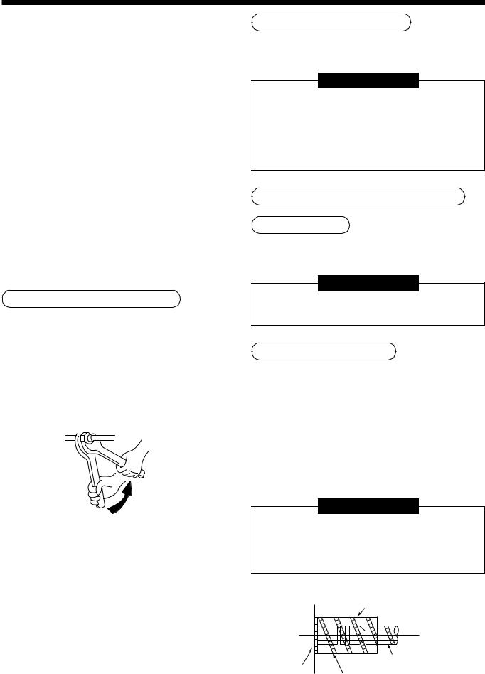
Removal of transporting rubbers
•Before installation of the indoor unit, remove the two protective rubbers for transportation which are inserted between the reinforcing bracket for the fan motor and the casing.
(Hand over the protective rubbers for transportation to the customers and ask to keep them because they are used for transportation such as reinstallation.)
Protective rubbers for transportation (remove) 
Pull upward to remove.
Reinforcing bracket |
Casing |
In case of wireless type
The sensor of indoor unit with wireless remote controller can receive a signal within approx. 8m. Based upon it, determine a place where the remote controller is operated and the installation place of the indoor unit.
•To prevent a malfunction, select a place where is not influenced by a florescent light or direct sunlight.
•Two or more (Up to 6 units) indoor units with wireless remote controller can be installed in the same room.
8m |
or |
|
|
|
less |
3 INSTALLATION OF INDOOR UNIT
WARNING
Install the air conditioner certainly to sufficiently withstand the weight.
If the strength is insufficient, the unit may fall down resulting in human injury.
Perform a specified installation work to guard against strong wind or earthquake.
An incomplete installation can cause accidents by the units falling and dropping.
REQUIREMENT
Strictly comply with the following rules to prevent damage of the indoor units and human injury.
•Do not put a heavy article on the indoor unit. (Even units are packaged)
•Carry in the indoor unit as it is packaged if possible. If carrying in the indoor unit unpacked by necessity, be sure to use buffering cloth, etc. to not damage the unit.
•To move the indoor unit, hold the hooking metals (4 positions) only.
Do not apply force to the other parts (refrigerant pipe, drain pan, foamed parts, or resin parts, etc.).
•Carry the package by two or more persons, and do not bundle it with PP band at positions other than specified.
•The hanging bolt pitch on longitudinal direction is not divided at center with the ceiling opening size. Therefore, check the relational position in the External view.
If relational position is incorrect, the check panel cannot be installed.
5
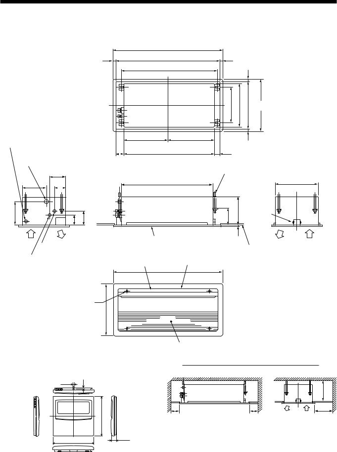
External view
Panel external dimension 1050
20 |
Ceiling open dimension |
20 |
1010 |
|
890 |
|
20 |
|
|
|
|
|
|
|
|
|
|
|
330 |
400 |
430 |
Ceiling open dimension |
470 |
Panel external dimension |
395 |
455 |
|
20 |
|
|
|
Power connecting port |
|
Center of panel |
|
|
110 |
850 |
50 |
Drain pipe connecting port |
|
|
|
(VP25) |
|
|
Hanging bolt |
|
|
|
|
|
150 |
|
4-M10 Arranged at site |
|
|
|
|
225 |
100 |
850 |
400 |
200 |
85 |
120 |
140 |
235 |
18
Support metal
Refrigerant pipe connecting port |
Ceiling panel |
Ceiling |
|
(Sold separately) |
|||
bottom surface |
|||
(Gas side Ø9.5) |
|
|
|
Refrigerant pipe connecting port |
|
|
|
(Liquid side Ø6.4) |
Discharge louver |
Discharge port |
|
|
1050 |
|
Panel mounting hole 5 positions
470
•Wired remote controller (RBC-AMT21E)
4 |
2.7 |
120
16
120
Air suction grille
Space necessary for installation and servicing
|
|
245 or more |
100 |
100 |
200 |
or more |
or more |
or more |
6
3 INSTALLATION OF INDOOR UNIT
Ceiling opening and installation of hanging bolts
•Considering pipe/wire connecting work inside the ceiling after the indoor unit has been hanged, select an installation place and determine piping direction.
•After installation place of the indoor unit has been determined, open the installation hole on the ceiling and install the hanging bolts.
•For the ceiling opening size and the hanging bolt pitch, refer to the external view and the attached installation pattern.
•If the ceiling has been already set up, draw the drain pipe, refrigerant pipe, indoor/outdoor inter-unit cable, cable for central control system, and remote controller cable up to the position where pipes and cables are to be connected before hanging the indoor unit.
Please procure the hanging bolts and nuts for installation of the indoor unit at local site.
Hanging bolt |
M10 or W3/8 |
4 pieces |
|
|
|
Nut |
M10 or W3/8 |
12 pieces |
|
|
|
Flat washer |
M10 |
8 pieces |
|
|
|
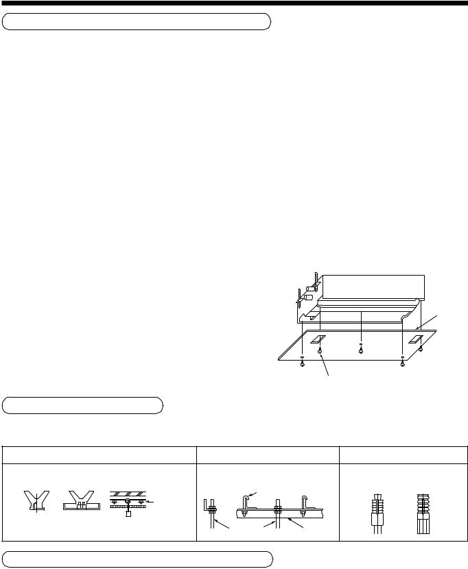
[How to use the attached installation pattern]
The installation pattern is attached inside of the package cap.
<In case of existing ceiling>
Use the installation pattern for positioning of the ceiling opening hole and the hanging bolt.
<In case of new ceiling>
Use the installation pattern for positioning of the opening hole when setting up a new ceiling.
•Install the indoor unit after installation of the hanging bolts.
•Using the attached installation pattern fixing screws (M5 × 20L: 4 pieces), attach the installation pattern to the indoor unit. (Screwing to installation brackets of the ceiling panel)
•When setting up the ceiling, open a hole along the outside dimension of the installation pattern.
Pattern sheet
Ceiling panel fixing screw (Use the attached screws.)
Installation of hanging bolts
Use M10 hanging bolts (4 pcs, to be local procure).
Matching to the existing structure, set pitch according to size in the unit external view as shown below.
|
New concrete slab |
Steel flame structure |
Existing concrete slab |
||
Install the bolts with insert brackets or anchor |
Use existing angles or install new |
Use a hole-in anchors, hole-in |
|||
bolts. |
|
|
support angles. |
|
plugs, or a hole-in bolts. |
|
|
Reinforcing |
Hanging bolt |
|
|
|
|
|
|
|
|
|
|
steel |
|
|
|
|
|
Anchor bolt |
|
|
|
(Blade type |
(Slide type |
(Pipe hanging |
|
|
|
bracket) |
bracket) |
anchor bolt) |
Hanging bolt |
Support angle |
|
|
|
|
|
||
Installation of remote controller (Sold separately)
For installation of the wired remote controller, follow the Installation Manual attached with the remote controller. For installation of the wireless remote controller, follow to the Installation Manual attached to the remote controller.
•Do not put the remote controller on the place where is exposed to direct sunlight or near a stove, etc.
•Operate the remote controller, check the indoor unit surely receives the signal, and then install the remote controller. (Wireless type)
•Install the remote controller 1m apart from the devices such as TV or stereo. (Image may be disturbed or noise may be output.) (Wireless type)
7
Installation of indoor unit
CAUTION
This unit is incorporated with drain pump and float switch. Never incline the main unit. Otherwise, malfunction of the float switch may be caused resulting in water leakage.
•Attach the nut (M10 or W3/8: Procured locally) and the attached washer (Ø34mm) to the hanging bolt.
•Adjust nut position (lower side) so that clearance between (lower side) and the lower side of ceiling board is 137mm.
•Hang up the main unit by hanging nut of hanging bolt to T groove of hanging bracket of the indoor unit.
•Using the level vial, etc., check the horizontal level of the indoor unit.
•Using the installation pattern, check and adjust the positional relation between the indoor unit and ceiling opening hole, and hanging-up height of the indoor unit.
Hanging bolt |
(1) |
M10 flat washer |
|
(W3/8 or M10) |
(Accessory) |
Nut |
(2) |
(W3/8 or M10) |
|
|
M10 flat washer |
Nut |
(Accessory) |
(W3/8 or M10) |
|
(1)Required those other than M10 flat washer at site.
(2)To prevent falling-off of bolt (safety), be sure to set it just under the hanging bracket as shown in the figure.
137mm
Hanging bolt
Nut (Upper side)
Washer
 (Upper side)

 (Hanging bracket main unit)
Washer (Lower side)
Nuts (Lower side)
Lower surface of ceiling
•The used screws when attaching the installation pattern are used again to install the panel.
•Using the ceiling panel fixing screws, fix the installation pattern
under surface of the indoor unit.
20
Opening part
• Fit the ceiling opening size to outside of the installation pattern.
(Ceiling opening dimension)
Installation pattern
Lower side of |
Lower surface |
installation pattern |
of ceiling |
695 |
110 |
Outline of indoor unit |
50 |
20
P0151, P0181 : 1160
P0241 : 1360
(Ceiling opening dimension)
• Match the bottom surface of ceiling and lower side of installation pattern on the same level.
Indoor unit |
|
Indoor unit |
|
Indoor unit |
|
|
|
|
Lower side of |
|
Drawing : 3mm or less |
installation pattern |
Lower surface |
Protruding : 0mm or more |
Match on the same level. |
of ceiling |
|
|
|
•Fix the indoor unit securely by tightening nut at upper side.
Level vial
Fix securely
REQUIREMENT
•Using a level vial, etc., confirm the horizontal level of the indoor unit.
•Tighten the nut sufficiently, and fix it securely.
Installation of ceiling panel (Sold separately)
Install the ceiling panel according to Installation Manual after piping/wiring work has completed.
Check that installation of indoor unit and ceiling opening part is correct, and then install it.
REQUIREMENT
Connect the connecting sections of ceiling panel and ceiling surface, and the ceiling panel and indoor unit closely.
If there is clearance, air leakage generates resulting in dewing or water leakage.
8
4 DRAIN PIPING WORK
CAUTION
•Following the Installation Manual, perform the drain piping work so that water is properly drained, and apply a heat insulation so as not to cause a dew. Inappropriate piping work may result in water leakage in the room and wet of furniture.
Pipe material/Insulator and size
The following materials for piping work and insulating process are procured locally.
Pipe material
Hard vinyl chloride pipe VP25 (Outer diameter Ø32mm)
Insulator
Foamed polyethylene foam, thickness: 10mm or more
REQUIREMENT
•Be sure to perform heat insulation of the drain pipes of the indoor unit.
•Never forget to perform heat insulation of the connecting part with the indoor unit. An incomplete heat insulation causes dewing.
Heat
• Set the drain pipe with downward slope (1/100 or more), and do not insulator make swelling or trap on the piping. It may cause an abnormal sound.
•For length of the traversing drain pipe, restrict to 20m or less. In case of a long pipe, provide support brackets with interval of 1.5 to 2m in order to prevent waving.
• |
Set the collective piping as shown in the right figure. |
|
As long as possible (10cm) |
|||||
• |
Do not mount an air purge pipe, |
|
|
|
VP25 |
|
VP25 |
|
|
|
|
|
|
|
|
||
|
otherwise drain water spouts |
(Collective pipes) |
|
|
|
|
|
|
|
|
|
|
|
|
|
||
|
|
|
|
|
|
|||
|
out resulted in water leak. |
|
|
|
|
|
|
|
1.5m to 2m |
Support |
|
bracket |
1/100 or more downward
Arched shape
Trap
VP25
VP30 or more |
Downward slope |
|
1/100 or more |
Connection of drain pipe
Connect hard vinyl chloride pipe to the drain piping port.
•Using adhesive agent for vinyl chloride, connect the hard vinyl chloride pipes certainly so that water does not leak.
•Apply adhesive agent around 40mm of the end of hard vinyl chloride pipe without unevenness, and then insert it surely until it strikes to the drain socket.
REQUIREMENT
•Using adhesive agent for vinyl chloride, connect the hard vinyl chloride pipes certainly so that water does not leak.
•It requires several times to dry and harden the adhesive agent.
(Refer to Guide Manual of the adhesive agent.) In this time, be sure not to apply force to the connecting section with the drain pipes.
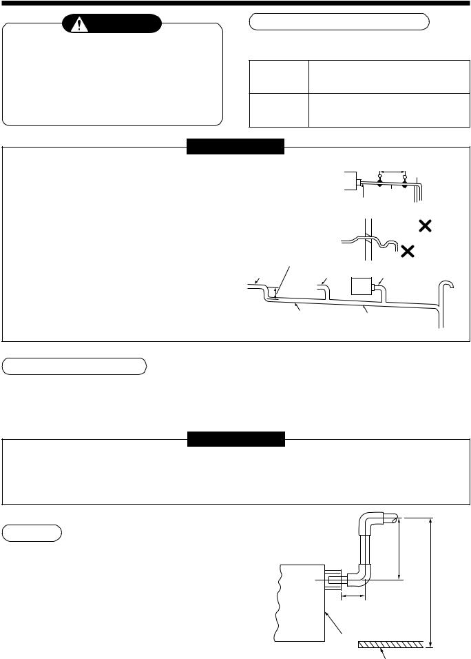
Drain up
When a downward grading cannot be secured on the drain pipe, a drain-up work is possible.
•Set the height of the drain pipe within 350mm from the bottom surface of the ceiling.
•Draw out the drain pipe within 150mm from the end of the drain pipe connecting port of the indoor unit, and then raise it vertically.
•After the drain pipe has been raised, set a grading so that it is immediately bent downward.
Rising up 150mm or less |
350mm or less |
|
100mm |
up |
|
Rising |
||
or less |
||
|
||
Indoor unit |
|
Underneath of ceiling
9
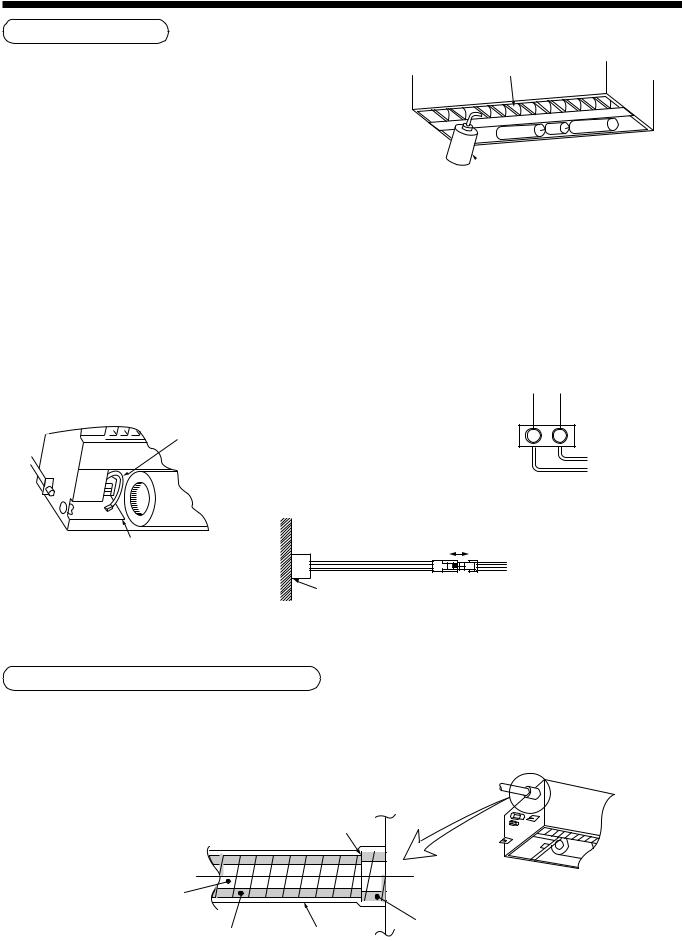
Check the draining
After drain piping work, check that water drain is properly performed and water does not leak from the connecting part of the pipes. In this time, check also there is no abnormal sound of the motor of the drain pump. Be sure to check draining when installed in the heating period.
When the electric work has finished:
Air outlet
 Pitcher
•Before installing a panel, pour water (500cc) as shown in the following figure, check water is drained from the drain pipe connecting port in COOL mode, and then check there is no water leak from the drain pipes.
When the electric work has not finished:
•Pull out the float switch connector (2P: White). (In this time, be sure to check the power is turned off.)
•Connect the single-phase 220-240V 50Hz (or 220V 60Hz) power to the terminal blocks R (L) and S (N). (Never apply 220-240V to (A), (B), (U1),and (U2), otherwise a trouble of P.C. board occurs.)
•When the power is turned on, the drain pump motor drives automatically. Check water is drained from the drain pipe connecting port, and then check there is no water leak from the drain pipes.
•After check of draining and water leak, turn off the power supply, attach the float switch connector to the original position.
Float switch connector (2P, White) |
|
(Lead wire color : Black) |
R(L) S(N) |
Single phase 220-240V, 50Hz
220V, 60Hz
Electric parts box |
Pull out |
|
|
Black |
White |
Black |
Float |
|
|
|
|
Black |
|
White Black |
switch |
|
|
||
P.C. board connector CN030 (Red)
Heat insulating of pipe connecting part
•Be sure to apply heat insulating securely to the pipe connecting part.
•Be sure to tape surely the butting part of the heat insulator
at the main unit side and at site so that no clearance generates.
Butt heat insulator without clearance.
Hard vinyl |
|
|
|
chloride pipe |
|
|
|
(Required at site) |
|
Heat insulator |
|
Heat insulator |
Using tape, |
||
(Main unit side) |
|||
(Required at site) |
fix the heat insulator. |
|
10
5 REFRIGERANT PIPING
 WARNING
•If refrigerant gas has leaked during the installation work, ventilate the room immediately.
•If the leaked refrigerant gas comes in contact with fire, noxious gas may generate.
•After the installation work, confirm that refrigerant gas does not leak.
•If refrigerant gas leaks into the room and flows near a fire source, such as a cooking range, noxious gas may generate.
REQUIREMENT
When the refrigerant pipe is long, set the support brackets to fix the pipe with 2.5 to 3m intervals. If the pipe is not fixed, abnormal sound may generate.
Be sure to use the flare nuts attached to the indoor unit or those for R410A.
Permissible pipe length and permissible height difference
They are different according to the used outdoor unit. For details, refer to the Installation Manual attached to the outdoor unit.
Piping material and dimensions
Piping material |
Phosphor deoxidization joint-less pipe for air conditioner |
||
|
|
||
Model MMU- |
AP0071YH to AP0121YH |
||
|
|
|
|
Pipe size (mm) |
Gas side |
Ø9.5 |
|
|
|
||
Liquid side |
Ø6.4 |
||
|
|||
|
|
|
|
• Use a clean and new pipe, and check that impurity such as dust, oil, moisture, etc. does not adhere in the pipe.
Pipe forming/End positioning |
• Flaring diam. meter size : A (Unit : mm) |
|||
|
|
|
||
Flaring |
|
Outer diam. of copper pipe |
|
A -+00.4 |
|
R410A |
R22 |
||
|
|
|
||
1. Cut the pipe with a pipe cutter. |
6.4 |
9.1 |
9.0 |
|
|
|
|||
|
|
9.5 |
13.2 |
13.0 |
90˚ |
Obliquity Roughness Warp |
12.7 |
16.6 |
16.2 |
|
|
15.9 |
19.7 |
19.2 |
2.Insert a flare nut into the pipe, and flare the pipe.
As the flaring sizes of R410A differ from those of refrigerant R22, the flare tools newly manufactured for R410A are recommended.
However, the conventional tools can be used by adjusting projection margin of the copper pipe.
B |
*In case of flaring for R410A with the conventional flare tool, pull it out approx. 0.5 mm more than that for R22 to adjust to the specified flare size.
The copper pipe gauge is useful for adjusting projection margin size.
A
11
• Projection margin in flaring : B (Unit : mm)
Rigid (Clutch type)
Outer diam. of |
R410A tool used |
Conventional tool used |
||
|
|
|
|
|
copper pipe |
R410A |
R22 |
R410A |
R22 |
|
||||
|
|
|
|
|
6.4 |
0 to 0.5 |
(Same as left) |
1.0 to 1.5 |
0.5 to 1.0 |
|
|
|
|
|
9.5 |
0 to 0.5 |
(Same as left) |
1.0 to 1.5 |
0.5 to 1.0 |
|
|
|
|
|
12.7 |
0 to 0.5 |
(Same as left) |
1.0 to 1.5 |
0.5 to 1.0 |
|
|
|
|
|
15.9 |
0 to 0.5 |
(Same as left) |
1.0 to 1.5 |
0.5 to 1.0 |
|
|
|
|
|
Imperial (Wing nut type)
Outer diam. of copper pipe |
R410A |
R22 |
|
|
|
6.4 |
1.5 to 2.0 |
1.0 to 1.5 |
|
|
|
9.5 |
1.5 to 2.0 |
1.0 to 1.5 |
|
|
|
12.7 |
2.0 to 2.5 |
1.5 to 2.0 |
|
|
|
15.9 |
2.0 to 2.5 |
1.5 to 2.0 |
|
|
|
Connection of refrigerant pipe
Connect all the refrigerant pipes with flare connecting work.
•Since the atmospheric pressure only is sealed as the sealing gas, it is not abnormal that “Pushu…” sound is not heard when the flare nut is removed.
•Be sure to use a double spanner for pipe connecting work of the indoor unit.
Work using double spanner
• Refer to the following table for tightening torque.
Connecting pipe |
Tightening torque |
Re-tightening |
outer dia. (mm) |
(N•m) |
torque (N•m) |
|
|
|
Ø6.4 |
14 to 18 (1.4 to 1.8 kgf•m) |
18 (1.8 kgf•m) |
|
|
|
Ø9.5 |
33 to 42 (3.3 to 4.2 kgf•m) |
42 (4.2 kgf•m) |
|
|
|
Ø12.7 |
50 to 62 (5.0 to 6.2 kgf•m) |
50 (5.0 kgf•m) |
|
|
|
Ø15.9 |
68 to 82 (6.8 to 8.2 kgf•m) |
68 (6.8 kgf•m) |
|
|
|
Airtight test/Air purge, etc.
For airtight test, air purge, addition of refrigerant, and gas leak check, follow the Installation Manual attached to the outdoor unit.
REQUIREMENT
Be sure to use the tool such as charge hose exclusive to R410A.
Do not turn on the power until the airtight test and the vacuuming have finished. (If turning on the power, the incorporated PMV is closed fully and the period until the vacuuming finishes elongates.
Open fully valves of the outdoor unit
Gas leak check
Check with a leak detector or soap water whether gas leaks or not, from the pipe connecting section or cap of the valve.
REQUIREMENT
Use a leak detector manufactured exclusively for HFC refrigerant (R410A, R134a, etc.).
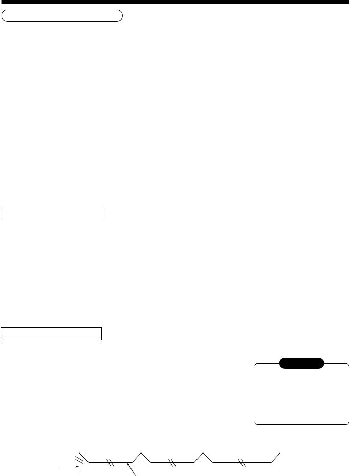
Heat insulating process
Perform heat insulating for pipes at liquid side and gas side separately.
In cooling time, temperature at both liquid and gas sides becomes lower.
Therefore, perform heat insulating process sufficiently to avoid dewing.
•For heat insulator of pipe at gas side, be sure to use one with heat-resisting temp.120°C or more.
•Using the attached heat insulating pipe, perform heat insulating process securely for pipe connecting part of the indoor units without clearance.
REQUIREMENT
Apply the thermal insulation to the pipe connecting section of the indoor unit securely up to the root without exposure of the pipe.
(The pipe exposed to the outside causes water leak.)
|
Set notching upward. |
|
Pipe side |
Main unit |
(Required at the site) |
|
|
|
Attached heat insulating pipe |
12
6 ELECTRIC WORK
 WARNING
1.Using the specified wires, ensure to connect the wires, and fix wires securely so that the external strength of the wires do not transmit to the connecting part of the terminals.
Incomplete connection or fixation may cause a fire, etc.
2.Be sure to connect earth wire. (Grounding work)
Do not connect the earth wire to gas pipe, city water pipe, lightning rod, or the earth wire of telephone.
Incomplete grounding causes an electric shock.
3.For electric work, strictly follow to the Local Regulation in each country and the Installation Manual, and use an exclusive circuit.
Capacity shortage of power circuit or incomplete installation may cause an electric shock or a fire.
 CAUTION
Be sure to install an earth leakage breaker.
If an earth leakage breaker is not installed, an electric shock may be caused.
REQUIREMENT
•For power supply wiring, strictly conform to the Local Regulation in each country.
•For wiring of power supply of the outdoor units, follow to the Installation Manual of each outdoor unit.
•Never connect 220–240V power to the terminal blocks (A, B, U1, U2, X, Y, etc.) for control wiring. (Otherwise, the system will be failed.)
•Perform the electric wiring so that it does not come to contact with the high-temperature part of the pipe. The coating may melt resulted in an accident.
•After connecting wires to the terminal blocks, provide a trap and fix wires with the wire clamp.
•Store the refrigerant piping line and control wiring line in the same line.
•Do not turn on the power of the indoor unit until vacuuming of the refrigerant pipes completes.
13
Power supply specifications
Power supply cord and communication wires are procured locally.
For the power supply specifications, follow to the table below. If capacity is little, it is dangerous because overheat or seizure may be caused.
For specifications of the power capacity of the outdoor unit and the power supply wires, refer to the Installation Manual attached to the outdoor unit.
|
Power supply |
220–240V ~ 50Hz |
|
|
220V ~ 60Hz |
||
Indoor unit power supply (*1) |
Power supply switch/Earth leakage breaker or power supply wiring/fuse rating for |
||
|
indoor units should be selected by the accummulated total current values of the indoor units. |
||
|
|
|
|
|
Power supply wiring |
20m or less |
Twist wire : 2.0 mm² |
|
|
|
|
|
50m or less |
Twist wire : 3.5 mm² |
|
|
|
||
|
|
|
|
|
|
Q’ty |
2 |
|
Indoor/Outdoor inter-unit wiring (*2) |
Wire size |
(Up to 1000m) Twist wire : 1.25 mm² |
|
|
(Up to 2000m) Twist wire : 2.00 mm² |
|
|
|
|
|
Communication line |
|
Q’ty |
2 |
Central control line wiring (*3) |
|
|
|
Wire size |
(Up to 1000m) Twist wire : 1.25 mm² |
||
|
|
(Up to 2000m) Twist wire : 2.00 mm² |
|
|
|
|
|
|
|
|
|
|
Remote controller wiring (*4) |
Q’ty |
2 |
|
|
|
|
|
Wire size |
Twist wire : 0.5 to 2.0 mm² |
|
|
|
||
|
|
|
|
Indoor unit power supply (*1)
•For the power supply of the indoor unit, prepare the exclusive power supply separated from that of the outdoor unit.
•Arrange the power supply, earth leakage breaker, and main switch of the indoor unit connected to the same outdoor unit so that they are commonly used.
•Power supply cord specification : Cable 3-core 2.5mm², in conformity with Design 60245 IEC 57.
Indoor/Outdoor inter-unit wiring, Central controller wiring |
(*2) (*3) |
•2-core with polarity wires are used for the Indoor/Outdoor inter-unit wiring and Central controller wiring.
•To prevent noise trouble, use 2-core shield wire.
•The length of the communication line means the total length of the inter-unit wire length between indoor and outdoor units added with the central control system wire length.
Remote controller wiring (*4)
•2-core with non-polarity wire is used for wiring of the remote controller wiring and group remote controllers wiring.
Remote controller wiring, remote |
Twist wire: 0.5mm2 |
to 2.0mm2 × 2 |
|
controller inter-unit wiring |
|||
|
|
||
|
|
|
Total wire length of remote controller |
In case of wired type only |
Up to 500m |
|
wiring and remote controller inter-unit |
|
|
|
In case of wireless type included |
Up to 400m |
||
wiring = L + L1 + L2 + … Ln |
|||
|
|
|
|
Total wire length of remote controller inter-unit wiring = L1 + L2 + … Ln |
Up to 200m |
||
|
|
|
|
CAUTION
The remote controller wire (Communication line) and AC220–240V wires cannot be parallel to contact each other and cannot be stored in the same conduits. If doing so, a trouble may be caused on the control system due to noise, etc.
|
Indoor unit |
|
Indoor unit |
|
Indoor unit |
|
Indoor unit |
|
Remote |
|
|
|
|
|
|
|
|
|
|
|
|
|
|
|
||
controller |
|
L1 |
|
L2 |
Ln |
|||
wiring |
|
|
||||||
Remote |
Remote controller inter-unit wiring |
(Max. 8 units) |
||||||
|
||||||||
|
controller |
|
|
|||||
|
|
|
|
|
|
|
||
|
|
|
|
|
|
|
|
|
14

6 ELECTRIC WORK
Cable connection
REQUIREMENT
•As the remote controller cable has no polarity, there is no problem if connections to indoor unit terminal blocks A and B are reversed.
•Be sure to pass the cable through the bushing of cable connection port of the indoor unit.
•Keep a margin (approx. 100m) on a cable to hang down the electric parts box at servicing, etc.
•The low-voltage circuit is provided for the remote controller. (Do not connect high-voltage circuit.)
How to remove cover of the electric parts box
•Take off the screw A fixing the electric parts box, and then loosen the screw B a little. Remove cover of the electric parts box by pushing the cover toward arrow direction C.
•Fasten the screws of the terminal block tightly and fix the wires with cord clamp attached to the electric parts box. (Do not apply tension to connecting part of the terminal block.)
•Be sure to make a loop on the connecting part of the wire to the electric parts storing section of the indoor unit; otherwise the electric storing section cannot be pulled out downward at service time.
•Mount cover of the electric parts box so as not to pinch the wires.
Screw A
Wire
Screw B C
DON’T APPLY 220-240V
FOR INTER-UNIT FOR REMOTE CONTROL |
FOR AI-NET |
U1 U2 A B X Y
Wire
Cord clamp Terminal block Electric parts box
R(L) S(N)
L N
10
10 |
|
30 |
70 |
Earth line
Connecting cable
Cable clamp
Treating of wiring connecting port
•As shown on the figure, seal the wire connecting port with heat insulator.
If sealing is insufficient, dewing is caused in the electric parts box.
Heat insulator (Required at site)
Cable
15
Remote controller wiring
•Strip off approx. 14mm cover of the wire to be connected.
•Twist wire of the remote controller to be connected with wire of the remote controller unit (or sensor), and press-fit them with a wire joint. (Wire joints (White: 2 pieces) are included in the accessory of the main remote controller (sold separately) or wireless remote controller kit (sold separately).)
•As the remote controller wire has no polarity, there is no problem if connections to indoor unit terminal blocks A and B are reversed.
<Wiring diagram>
Terminal block
for remote controller wiring of indoor unit
A
B
Remote controller wire (Local procure)
Approx. 200mm |
W : White |
||||||
|
|
|
|
|
|
|
B : Black |
|
|
W |
|
|
|
|
|
|
|
|
|
|
|
Remote |
|
|
|
|
|
|
|
||
|
|
B |
|
|
|
|
controller unit |
|
|
|
|
|
|
|
or sensor part |
|
|
|
|
|
|
|
|
|
|
|
|
|
|
|
|
Connecting |
Wire from remote controller unit |
||||||
part |
or sensor |
|
|||||
Remote controller wiring
Wire from remote  controller or sensor Wire joint
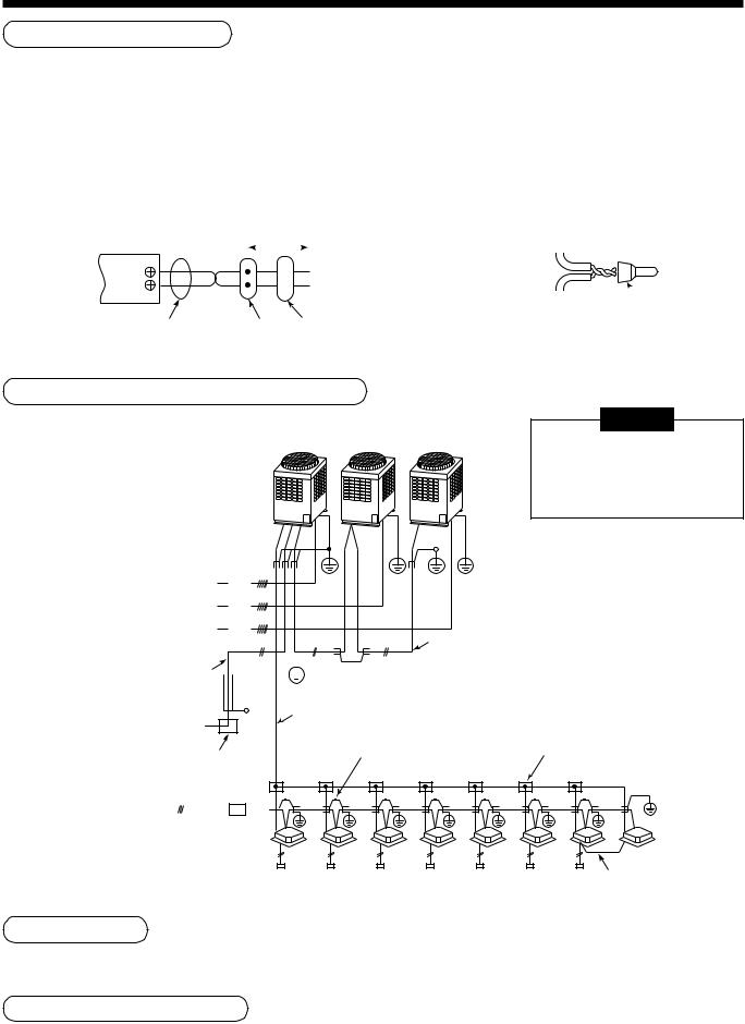
Wiring between indoor and outdoor units
|
|
NOTE |
Header unit |
Follower unit |
An outdoor unit connected |
|
|
|
|
|
with indoor/outdoor inter-unit |
|
|
wire becomes automatically |
|
|
the header unit. |
Earth leakage breaker
Outdoor power supply |
|
|
|
|
|
|
(Earth) |
Earth |
|
|
|
|
|
||||||
|
|
|
|
|
|
|
|
||
3-phase |
|
|
|
|
|
|
|
|
|
|
|
|
|
|
|
|
|
||
380–415V, 50Hz |
|
|
|
|
|
|
Inter-unit wire between outdoor units |
||
|
|
|
|
|
|
||||
380V, 60Hz |
|
|
|
|
|
|
|||
Central control line wire |
|
|
|
|
|||||
|
Connection of shield |
|
|||||||
|
|
||||||||
|
|
|
|
|
|
|
|
||
|
|
|
(Open) |
|
wire closed terminal |
|
|||
|
|
|
|
|
|
|
|||
Power supply |
Indoor/Outdoor inter-unit wire |
||||||||
220–240V ~ 50Hz |
|
|
|
|
|
|
|
||
220V ~ 60Hz |
|
|
|
|
Connection of shield |
Pull box |
|||
|
|||||||||
Remote controller, |
|
wire closed terminal |
|||||||
|
|
|
|
||||||
for central control, etc. |
|
|
|
|
|||||
(Earth)
Indoor power supply |
Earth leakage breaker |
|
||||
220–240V ~ 50Hz |
|
|
|
|
|
|
|
|
|
|
|
|
|
|
|
|
|
|
|
|
|
|
|
|
|
|
|
220V ~ 60Hz |
|
|
Switch |
|
||
Indoor unit |
(Remote controller group operation) |
Address setup
Set up the addresses according to the Installation Manual attached to the outdoor unit.
Wiring on the ceiling panel
According to the Installation Manual of the ceiling panel, connect the connector.
16
7 APPLICABLE CONTROLS
NOTIFICATION
When using the equipment at the first time, it will take a lot of time that the remote controller accepts an operation after power was on. However, it is not a trouble.
•Automatic address
•While automatic addressing, the operation cannot be performed on the remote controller.
•For automatic addressing, Max. 10 minutes (generally, approx. 5 minutes) are required.
•When power will be turned on after finish of automatic addressing;
•It will require Max. 10 minutes (generally, approx. 3 minutes) that outdoor unit starts operation after power was on.
As all have been set to [Standard] at the shipment, change the setup of the indoor unit if necessary. To change the setup, use the main remote controller (wired remote controller).
*The setup change for wireless remote controller, sub remote controller, or remote controller-less system (Central control remote controller only is provided.) is impossible. In these cases, prepare and mount a separate main remote controller.
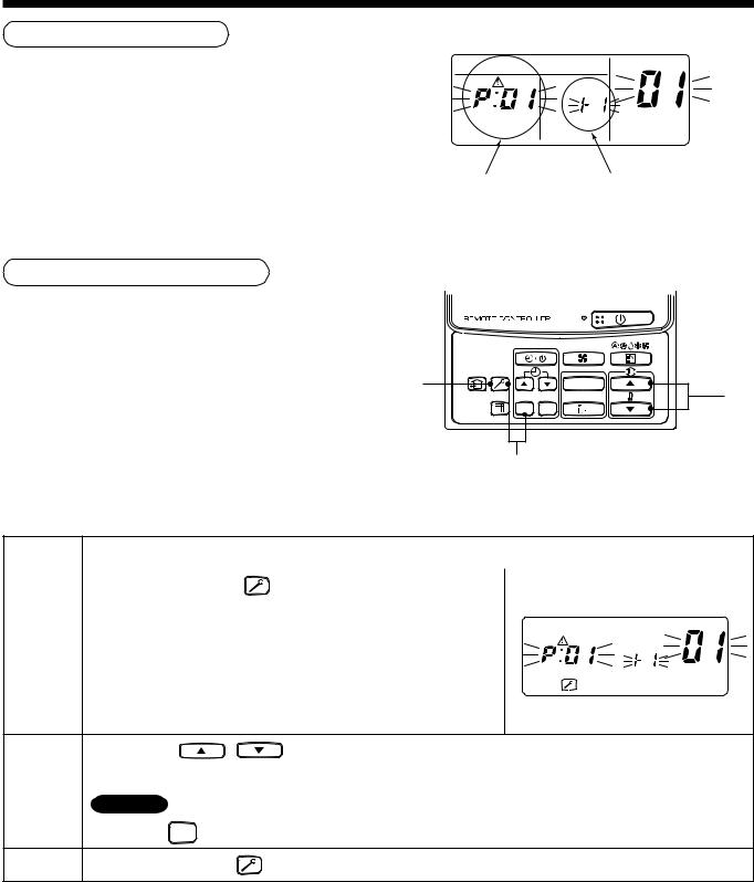
Exchange of applicable control setup
Basic operation procedure for setup exchange
Change the setup while operation of the equipment stops.
(Be sure to stop the operation of a set.)
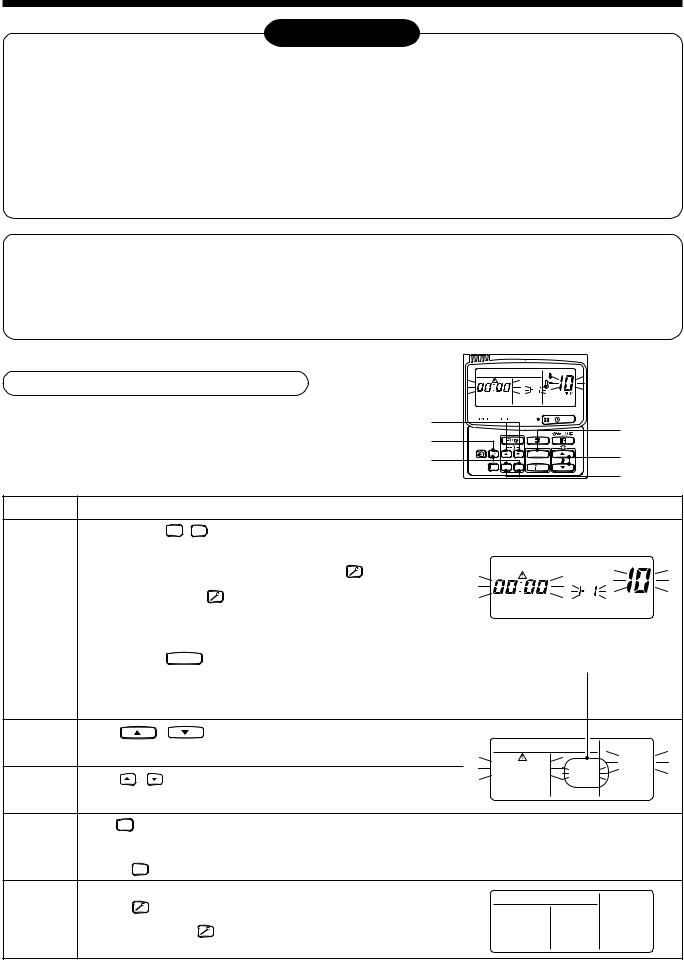
4
6
1
 CODE No.
SET DATA
UNIT No.
R.C. No.
|
UNIT |
SET |
CL |
2
3
5
Procedure |
Description |
When pushing SET , CL , and  buttons simultaneously for 4 seconds or more, after a while, the display part flashes as shown in the figure.
|
Check that the displayed item code is [10]. |
button to erase |
|
|
|
|
CODE No. |
||
|
|
|
|
|
|||||
1 |
• If the item code indicates other than [10], push |
|
|
|
|
||||
|
|
|
|
|
|||||
* |
UNIT No. |
|
|||||||
the display, and then retry the operation from the first step. |
|
|
|
|
|
||||
|
(For some time after |
button has been pushed, the operation of |
|
R.C. No. |
|
||||
|
the remote controller cannot be accepted.) |
|
|
|
|
|
|
||
|
(In a group control, the firstly displayed |
(* The display changes according to the indoor unit model.) |
|||||||
|
indoor unit No. becomes the header unit.) |
||||||||
|
|
|
|||||||
|
Every pushing UNIT |
button, the indoor unit No. in the group control is displayed successively. Select an |
|||||||
2 |
indoor unit of which setup to be changed. |
|
|
|
|
|
|
|
|
|
|
|
|
|
|
|
|||
In this time, the position of the indoor unit of which setup to be |
|
|
|
|
|
||||
|
changed can be confirmed because the fan and the flap of the |
|
|
|
|
|
|||
|
selected indoor unit work. |
|
|
|
|
|
|
||
3 |
Using |
|
, |
buttons of set temperature, specify the item |
|
|
|
code [**]. |
|
|
|
|
CODE No. |
||
|
|
|
|
|
**** |
UNIT No. |
** |
4 |
Using |
, |
|
buttons of timer time, select set data [****]. |
**** |
||
|
|
|
|
|
R.C. No. |
|
|
|
|
|
|
|
|
|
|
|
Push SET button. In this time, if the display changes from flashing to lighting, the setup completes. |
|
5 |
• |
To change the setup of an indoor unit other than the selected one, start operation from Procedure 2. |
• |
To change the setup of another setup in the selected indoor unit, start operation from Procedure 3. |
|
Pushing CL button clears the set up contents which have been already set. In this case, retry from Procedure 2.
When the setup finished, push  button. (The setup is determined.)
6 |
Pushing |
button deletes the display and returns the status to |
|
normal stop status. |
|
||
(For some time after |
button has been pushed, the operation of |
||
|
the remote controller cannot be accepted.) |
||
17
Change of lighting term of filter sign
According to the installation condition, the lighting term of the filter sign (Notification of filter cleaning) can be changed.
Follow to the basic operation procedure
(1 → 2 → 3 → 4 → 5 → 6 ).
•For the item code in Procedure 3 , specify [01].
•For the [Set data] in Procedure 4 , select the setup data of filter sign lighting term from the following table.
Setup data |
Filter sign lighting term |
|
|
|
|
0000 |
|
None |
|
|
|
0001 |
150H |
(At shipment from factory) |
|
|
|
0002 |
2500H |
|
|
|
|
0003 |
5000H |
|
|
|
|
0004 |
10000H |
|
|
|
|
To secure better effect of heating
When it is difficult to obtain satisfactory heating due to installation place of the indoor unit or structure of the room, the detection temperature of heating can be raised. Also use a circulator, etc. to circulate heat air near the ceiling.
Follow to the basic operation procedure
(1 → 2 → 3 → 4 → 5 → 6 ).
•For the item code in Procedure 3 , specify [06].
•For the set data in Procedure 4 , select the setup data of shift value of detection temperature to be set up from the table below.
Setup data |
Detection temp shift value |
|
|
0000 |
No shift |
|
|
0001 |
+1°C |
|
|
0002 |
+2°C (At shipment from factory) |
|
|
0003 |
+3°C |
|
|
0004 |
+4°C |
|
|
0005 |
+5°C |
|
|
0006 |
+6°C |
|
|
Group control
In a group control, a remote controller can control up to maximum 8 units.
•For cabling procedure and cables of the individual line (Identical refrigerant line) system, refer to “Electric work” in this Manual.
•Cabling between indoor units in a group is performed in the following procedure.
Connect the indoor units by connecting the remote controller inter-unit cables from the remote controller terminal blocks (A, B) of the indoor unit connected with a remote controller to the remote controller terminal blocks (A, B) of the other indoor unit.
(No polarity)
•For address setup, refer to the Installation Manual attached to the outdoor unit.
18
8 TEST RUN
Before test operation |
WARNING |
•Before turning on the power supply, carry out the following items.
1)Using 500V-megger, check there is 1MΩ or more between the terminal block of the power supply and the earth. If 1MΩ or less is detected, do not run the unit.
2)Check that all the valves of the outdoor unit are fully opened.
To protect the compressor at starting time, keep power-ON condition before 12 hours or more.
•Never push the electromagnetic contactor to carry out a forced test operation. (It is very dangerous because a protective device does not work.)
How to execute test operation
•To carry out a fan operation in a single indoor unit, turn off the power once, short CN72 on P.C. board, and then turn on the power again. (Start the unit in FAN mode.) In this case, do not forget to clear short-circuit of CN72 after test operation.
•Using the remote controller, check the operation in the usual operation. For the operation procedure, refer to the attached Owner’s Manual.
A forced test operation can be executed in the following procedure under condition of thermo-OFF of room temperature.
In order to prevent a serial operation, the forced test operation is released after 60 minutes and returns to the usual operation.
|
|
NOTE |
|
2, 4 |
|
Do not use a forced operation in cases other |
|
3 |
|||
than test operation because it applies an |
1, 5 |
||||
excessive load to the air conditioner. |
UNIT |
||||
|
|||||
|
|
|
|
SET CL |
|
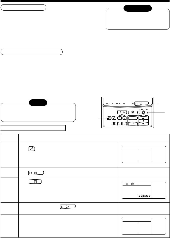
In case of wired remote controller |
|
|
|||
Procedure |
|
|
Description |
|
|
1 |
Keep |
button pushed for 4 seconds or more. [TEST] is |
|
||
displayed on the display part and the selection of mode in the test |
|
||||
|
|
||||
|
mode is permitted. |
|
TEST |
||
2 |
Push |
button. |
|
|
|
|
Using |
button, select the operation mode, [COOL] or [HEAT]. |
|
||
3 |
• Do not run the air conditioner in a mode other than [COOL] or [HEAT]. |
|
|||
• The temperature controlling function does not work during test |
|
||||
|
operation. |
|
|
||
|
• The detection of error is performed as usual. |
|
|||
4 |
After the test operation, push |
button to stop the operation. |
|
||
(Display part is same as procedure 1 ) |
|
|
|||
|
|
|
|||
Push  button to cancel (release from) the test operation mode.
5 ([TEST] disappears on the display part and the status returns to a normal stop status.)
19
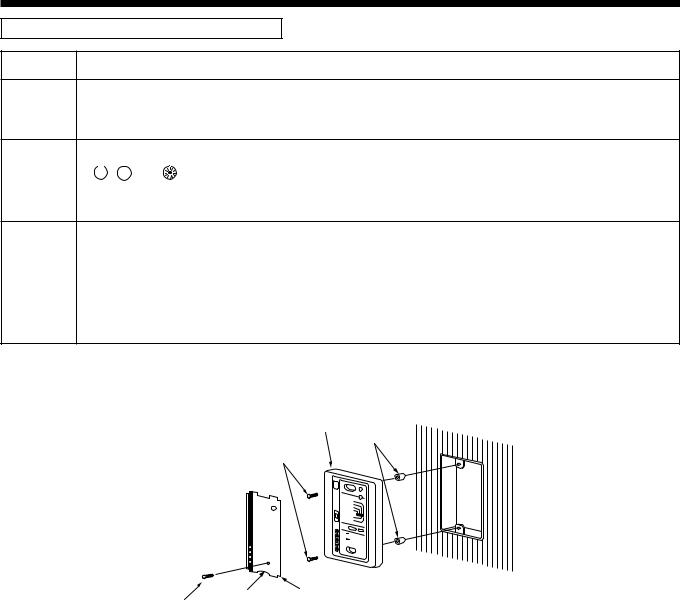
In case of wireless remote controller
Procedure |
Description |
Remove a small screw which fixes the nameplate of the receiver unit.
1 Remove the nameplate of the sensor section by inserting a minus screwdriver, etc into the notch at the bottom of the plate, and set the Dip switch to [TEST RUN ON].
Execute a test operation with  button on the wireless remote controller.
2 |
• |
|
, |
|
, and |
LED flash during test operation. |
|
|
|||||
|
|
|||||
• |
Under status of [TEST RUN ON], the temperature adjustment from the wireless remote controller is invalid. |
|||||
Do not use this method in the operation other than test operation because the equipment is damaged.
3 |
Use either COOL or HEAT operation mode for a test operation. |
|
* The outdoor unit does not operate approx. 3 minutes after power-ON and operation stop. |
||
|
|
|
4 |
After the test operation finished, stop the air conditioner from the wireless remote controller, and return Dip |
|
switch of the receiver section as before. |
||
|
||
|
(A 60-minutes timer clearing function is attached to the receiver section in order to prevent a continuous test |
|
|
operation.) |
Receiver unit
Spacer
M4 × 25 screw (2 pieces)
Notch Nameplate
Small screw
20
9 TROUBLESHOOTING
Confirmation and check
When a trouble occurred in the air conditioner, the check code and the indoor unit No. appear on the display part of the remote controller.
The check code is only displayed during the operation.
If the display disappears, operate the air conditioner according to the following “Confirmation of error history” for confirmation.
|
CODE No. |
|
UNIT No. |
|
R.C. No. |
Check code |
Indoor unit No. in which |
|
an error occurred |
Confirmation of error history
When a trouble occurred on the air conditioner, the error history can be confirmed with the following procedure.
(The error history is stored in memory up to 4 errors.)
This history can be confirmed from either operating |
3 |
UNIT |
2 |
|
status or stop status. |
||||
|
||||
|
SET CL |
|
1
Procedure |
|
Description |
|
|
|
||
|
|
|
|
|
|
||
|
When pushing [SET] and |
buttons simultaneously for 4 seconds |
|
|
|
||
|
or more, the right display appears. |
|
|
|
|||
|
If [Service Check] is displayed, the mode enters in the error history |
|
|
|
CODE No. |
||
|
|
|
|||||
1 |
mode. |
|
|
UNIT No. |
|
||
|
|
|
|||||
• [01: Order of error history] is displayed in CODE No. window. |
|
||||||
R.C. |
No. |
|
|||||
|
• [Check Code] is displayed in CHECK window. |
|
|||||
|
|
|
|
|
|||
•[Indoor unit address in which an error occurred] is displayed in UNIT No.
|
Every pushing |
, |
buttons, the error history stored in the memory is displayed in order. |
2 |
The numbers in CODE No. indicates CODE No. [01] (Latest) → [04] (Oldest). |
||
CAUTION |
|
|
|
|
|
|
|
|
Do not push CL |
button because all the error history of the indoor unit will be deleted. |
|
3 |
After confirmation, push |
button to return to the usual display. |
|
21

Check method
On the remote controller (Main remote controller, Central control remote controller) and the interface P.C. board of the outdoor unit (I/F), a check display LCD (Remote controller) or 7-segment display (on the outdoor interface P.C. board) to display the operation is provided. Therefore the operation status can be known. Using this self-diagnosis function, a trouble or position with error of the air conditioner can be found as shown in the table below.
Check code list
The following list shows each check code. Find the check contents from the list according to part to be checked.
•In case of check from indoor remote controller: See “Main remote controller display” in the list.
•In case of check from outdoor unit: See “Outdoor 7-segment display” in the list.
•In case of check from AI-NET central control remote controller: See “AI-NET central control display” in the list.
•In case of check from indoor unit with wireless remote controller: See “Sensor block display of receiving unit” in the list.
Terminology |
AI-NET : Artificial Intelligence. |
IPDU : Intelligent Power Drive Unit |
|
|
¡ : Lighting, ¤: Flashing, l : Goes off |
|
ALT. : Flashing is alternately when there are two flashing LED. |
|
SIM : Simultaneous flashing when there are two flashing LED. |
|
|
|
Check code |
|
Wireless remote controller |
|
|
|||
|
|
|
|
|
|
|
|
|
||
Main |
|
Outdoor 7-segment display |
AI-NET central |
Sensor block display |
Check code name |
Judging device |
||||
remote |
|
|
|
of receiving unit |
|
|
||||
controller |
|
|
|
control display |
|
|
|
|
|
|
display |
|
|
Auxiliary code |
|
Operation |
Timer Ready |
Flash |
|
|
|
|
|
|
|
|
|
|
|
|
|
|
E01 |
— |
|
— |
— |
¤ |
|
|
|
Communication error between indoor and |
Remote controller |
|
|
|
|
|||||||
|
|
|
|
|||||||
|
l |
l |
|
remote controller |
||||||
|
|
|
||||||||
|
|
|
|
|
|
|
|
|
(Detected at remote controller side) |
|
|
|
|
|
|
|
|
|
|
|
|
|
|
|
|
|
|
|
|
|
|
|
E02 |
— |
|
— |
— |
¤ |
l |
l |
|
Remote controller transmission error |
Remote controller |
|
|
|
||||||||
|
|
|
|
|
|
|
|
|
|
|
E03 |
— |
|
— |
97 |
¤ |
l |
l |
|
Communication error between indoor and |
Indoor |
|
|
|||||||||
|
|
|||||||||
|
|
remote controller (Detected at indoor side) |
||||||||
|
|
|||||||||
E04 |
— |
|
— |
04 |
l |
l |
¤ |
|
Communication circuit error between indoor/ |
Indoor |
|
|
|||||||||
|
|
outdoor (Detected at indoor side) |
||||||||
|
|
|||||||||
|
|
|
|
|
|
|
|
|
|
|
|
|
|
No. of indoor units in which |
|
l |
l |
¤ |
|
|
|
|
|
|
|
|
|
|
||||
E06 |
E06 |
|
sensor has been normally |
04 |
|
Decrease of No. of indoor units |
I/F |
|||
|
|
|||||||||
|
|
|
received |
|
|
|
|
|
|
|
|
|
|
|
|
|
|
|
|
|
|
— |
E07 |
|
— |
— |
l |
l |
¤ |
|
Communication circuit error between indoor/ |
I/F |
|
|
|||||||||
|
|
outdoor (Detected at outdoor side) |
||||||||
|
|
|
|
|
|
|
|
|
||
|
|
|
|
|
|
|
|
|
|
|
E08 |
E08 |
|
Duplicated indoor addresses |
96 |
¤ |
l |
l |
|
Duplicated indoor addresses |
Indoor / I/F |
|
|
|||||||||
|
|
|||||||||
|
|
|||||||||
E09 |
— |
|
— |
99 |
¤ |
l |
l |
|
Duplicated main remote controllers |
Remote controller |
|
|
|||||||||
|
|
|||||||||
E10 |
— |
|
— |
CF |
¤ |
l |
l |
|
Communication error between indoor MCU |
Indoor |
|
|
|
||||||||
|
|
|
|
|
|
|
|
|
|
|
|
|
|
01: Indoor/Outdoor |
|
¤ |
|
|
|
|
|
|
|
|
|
|
|
|
|
|
||
|
|
|
|
|
|
|
|
|
||
E12 |
E12 |
|
communication |
42 |
l |
l |
|
Automatic address start error |
I/F |
|
|
|
|||||||||
|
02: Communication between |
|
||||||||
|
|
|
|
|
|
|
|
|
||
|
|
|
outdoor units |
|
|
|
|
|
|
|
|
|
|
|
|
|
|
|
|
|
|
|
|
|
|
|
|
|
|
|
|
|
|
|
|
|
|
|
|
|
|
|
|
E15 |
E15 |
|
— |
42 |
l |
l |
¤ |
|
Indoor is nothing during automatic addressing |
I/F |
|
|
|||||||||
|
|
|
|
|
|
|
|
|
|
|
E16 |
E16 |
|
00: Capacity over |
89 |
l |
l |
¤ |
|
Capacity over / No. of connected indoor units |
I/F |
|
|
|||||||||
|
|
|||||||||
|
01 ~:No. of connected units |
|
||||||||
|
|
|||||||||
|
|
|
|
|
|
|
|
|
||
E18 |
— |
|
— |
97, 99 |
¤ |
l |
l |
|
Communication error between indoor units |
Indoor |
|
|
|
||||||||
|
|
|
|
|
|
|
|
|
|
|
E19 |
E19 |
|
00: Header is nothing |
96 |
l |
l |
¤ |
|
Outdoor header units quantity error |
I/F |
|
|
|||||||||
|
02: Two or more header units |
|
||||||||
|
|
|
|
|
|
|
|
|
||
|
|
|
|
|
|
|
|
|
|
|
|
|
|
01: Outdoor of other line |
|
|
|
¤ |
|
Other line connected during automatic |
|
|
|
|
|
|
|
|
|
|||
|
|
|
|
|
|
|
|
|||
E20 |
E20 |
|
connected |
42 |
l |
l |
|
I/F |
||
|
|
|||||||||
|
02: Indoor of other line |
|
address |
|||||||
|
|
|||||||||
|
|
|
connected |
|
|
|
|
|
|
|
|
|
|
|
|
|
|
|
|
|
|
|
|
|
|
|
|
|
|
|
|
|
E23 |
E23 |
|
— |
15 |
l |
l |
¤ |
|
Sending error in communication between |
I/F |
|
|
|||||||||
|
|
outdoor units |
||||||||
|
|
|||||||||
|
|
|
|
|
|
|
|
|
|
|
E25 |
E25 |
|
— |
15 |
l |
l |
¤ |
|
Duplicated follower outdoor addresses |
I/F |
|
|
|||||||||
|
|
|||||||||
E26 |
E26 |
|
No. of outdoor units which |
15 |
l |
l |
¤ |
|
Decrease of No. of connected outdoor units |
I/F |
|
|
|||||||||
|
received signal normally |
|
||||||||
|
|
|
|
|
|
|
|
|
||
|
|
|
|
|
|
|
|
|
|
|
E28 |
E28 |
|
Detected outdoor unit number |
d2 |
l |
l |
¤ |
|
Follower outdoor unit error |
I/F |
|
|
|||||||||
|
|
|
||||||||
|
|
|
01: IPDU1 error |
|
|
|
|
|
|
|
|
|
|
|
|
|
|
|
|
|
|
|
|
|
02: IPDU2 error |
|
|
|
|
|
|
|
|
|
|
|
|
|
|
|
|
|
|
|
|
|
03: IPDU1, 2 error |
|
l |
l |
¤ |
|
|
|
|
|
|
|
|
|
|
||||
E31 |
E31 |
|
04: Fan IPDU error |
CF |
|
IPDU communication error |
I/F |
|||
|
|
|||||||||
|
|
|
05: IPDU + Fan IPDU error |
|
|
|
|
|
|
|
|
|
|
06: IPDU2 + Fan IPDU error |
|
|
|
|
|
|
|
|
|
|
|
|
|
|
|
|
|
|
|
|
|
07: All IPDU error |
|
|
|
|
|
|
|
|
|
|
|
|
|
|
|
|
|
|
22

9 TROUBLESHOOTING
|
|
|
|
Check code |
|
Wireless remote controller |
|
|
|||
|
|
|
|
|
|
|
|
|
|
||
Main |
|
Outdoor 7-segment display |
AI-NET central |
Sensor block display |
Check code name |
Judging device |
|||||
remote |
|
|
|
|
of receiving unit |
|
|
||||
controller |
|
|
|
|
control display |
|
|
|
|
|
|
display |
|
|
|
Auxiliary code |
|
Operation |
Timer Ready |
Flash |
|
|
|
F01 |
— |
|
|
— |
0F |
¤ |
¤ l |
ALT |
Indoor TCJ sensor error |
Indoor |
|
|
|
||||||||||
|
|
||||||||||
F02 |
— |
|
|
— |
0d |
¤ |
¤ l |
ALT |
Indoor TC2 sensor error |
Indoor |
|
|
|
||||||||||
|
|
||||||||||
F03 |
— |
|
|
— |
93 |
¤ |
¤ |
l |
ALT |
Indoor TC1 sensor error |
Indoor |
|
|
|
|
||||||||
F04 |
F04 |
|
|
— |
19 |
¤ |
¤ ¡ |
ALT |
TD1 sensor error |
I/F |
|
|
|
||||||||||
|
|
||||||||||
F05 |
F05 |
|
|
— |
A1 |
¤ |
¤ ¡ |
ALT |
TD2 sensor error |
I/F |
|
|
|
||||||||||
|
|
||||||||||
F06 |
F06 |
|
|
— |
18 |
¤ |
¤ ¡ |
ALT |
TE1 sensor error |
I/F |
|
|
|
||||||||||
|
|
||||||||||
F07 |
F07 |
|
|
— |
18 |
¤ |
¤ ¡ |
ALT |
TL sensor error |
I/F |
|
|
|
||||||||||
|
|
||||||||||
F08 |
F08 |
|
|
— |
1b |
¤ |
¤ ¡ |
ALT |
TO sensor error |
I/F |
|
|
|
||||||||||
|
|
|
|
|
|
|
|
|
|||
F10 |
— |
|
|
— |
OC |
¤ |
¤ l |
ALT |
Indoor TA sensor error |
Indoor |
|
|
|
||||||||||
|
|
||||||||||
F12 |
F12 |
|
|
— |
A2 |
¤ |
¤ ¡ |
ALT |
TS1 sensor error |
I/F |
|
|
|
||||||||||
|
|
||||||||||
F13 |
F13 |
|
|
01: Comp. 1 side |
43 |
¤ |
¤ ¡ |
ALT |
TH sensor error |
IPDU |
|
|
|
02: Comp. 2 side |
|||||||||
|
|
|
|
|
|
|
|
||||
F15 |
F15 |
|
|
— |
18 |
¤ |
¤ ¡ |
ALT |
Outdoor temp. sensor miscabling (TE, TL) |
I/F |
|
|
|
||||||||||
|
|
||||||||||
F16 |
F16 |
|
|
— |
43 |
¤ |
¤ ¡ |
ALT |
Outdoor pressure sensor miscabling (Pd, Ps) |
I/F |
|
|
|
||||||||||
|
|
||||||||||
F23 |
F23 |
|
|
— |
43 |
¤ |
¤ ¡ |
ALT |
Ps sensor error |
I/F |
|
|
|
||||||||||
|
|
||||||||||
F24 |
F24 |
|
|
— |
43 |
¤ |
¤ ¡ |
ALT |
Pd sensor error |
I/F |
|
|
|
||||||||||
|
|
||||||||||
F29 |
— |
|
|
— |
12 |
¤ |
¤ |
l |
SIM |
Indoor other error |
Indoor |
|
|
|
|
||||||||
|
|
|
|
|
|
|
|
|
|
|
|
F31 |
F31 |
|
|
— |
1C |
¤ |
¤ ¡ |
SIM |
Indoor EEPROM error |
I/F |
|
|
|
||||||||||
|
|
||||||||||
H01 |
H01 |
|
|
01: Comp. 1 side |
IF |
l |
¤ |
l |
|
Compressor break down |
IPDU |
|
|
|
|||||||||
|
|
|
|||||||||
|
|
02: Comp. 2 side |
|
||||||||
|
|
|
|
|
|
|
|
|
|
||
H02 |
H02 |
|
|
01: Comp. 1 side |
1d |
|
¤ |
|
|
Magnet switch error |
MG-SW |
|
|
|
|
|
|||||||
|
|
l |
l |
|
Overcurrent relay operation |
Overcurrent relay |
|||||
|
|
|
|
02: Comp. 2 side |
|
|
|
|
Compressor trouble (lock) |
IPDU |
|
H03 |
H03 |
|
|
01: Comp. 1 side |
17 |
l |
¤ |
l |
|
Current detect circuit system error |
IPDU |
|
|
|
|||||||||
|
|
|
|||||||||
|
|
02: Comp. 2 side |
|
||||||||
|
|
|
|
|
|
|
|
|
|
||
H04 |
H04 |
|
|
— |
44 |
l |
¤ |
l |
|
Comp 1 case thermo operation |
I/F |
|
|
|
|
||||||||
|
|
|
|
|
|
|
|
|
|
|
|
H06 |
H06 |
|
|
— |
20 |
l |
¤ |
l |
|
Low pressure protective operation |
I/F |
|
|
|
|||||||||
|
|
|
|||||||||
H07 |
H07 |
|
|
— |
d7 |
l |
¤ |
l |
|
Oil level down detective protection |
I/F |
|
|
|
|||||||||
|
|
|
|
||||||||
|
|
|
|
|
|
|
|
|
|
|
|
|
|
|
|
01: TK1 sensor error |
d4 |
|
¤ |
|
|
|
|
|
|
|
|
|
|
|
|
|
|||
H08 |
H08 |
|
|
02: TK2 sensor error |
l |
l |
|
Oil level detective temp sensor error |
I/F |
||
|
|
03: TK3 sensor error |
|
|
|||||||
|
|
|
|
04: TK4 sensor error |
|
|
|
|
|
|
|
|
|
|
|
|
|
|
|
|
|
|
|
H14 |
H14 |
|
|
— |
44 |
l |
¤ |
l |
|
Comp 2 case thermo operation |
I/F |
|
|
|
|||||||||
|
|
|
|
||||||||
|
|
|
|
|
|
|
|
|
|
|
|
|
|
|
|
01: TK1 oil circuit system error |
|
|
¤ |
|
|
Oil level detective circuit error |
I/F |
|
|
|
|
|
|
|
|
||||
H16 |
H16 |
|
|
02: TK2 oil circuit system error |
d7 |
|
|
|
|||
|
|
l |
l |
|
Magnet switch error |
MG-SW |
|||||
|
|
03: TK3 oil circuit system error |
|
||||||||
|
|
|
|
|
|
|
|
Overcurrent relay operation |
Overcurrent relay |
||
|
|
|
|
04: TK4 oil circuit system error |
|
|
|
|
|
||
|
|
|
|
|
|
|
|
|
|||
|
|
|
|
|
|
|
|
|
|
|
|
|
|
|
|
|
|
|
|
|
|
|
|
L03 |
— |
|
|
— |
96 |
¤ |
l |
¤ |
SIM |
Indoor center unit duplicated |
Indoor |
|
|
||||||||||
|
|
||||||||||
L04 |
L04 |
|
|
— |
96 |
¤ |
¡ |
¤ |
SIM |
Outdoor line address duplicated |
I/F |
|
|
||||||||||
|
|
|
|||||||||
L05 |
— |
|
|
— |
96 |
¤ |
l |
¤ |
SIM |
Duplicated indoor units with priority |
I/F |
|
|
||||||||||
|
|
(Displayed in indoor unit with priority) |
|||||||||
|
|
||||||||||
|
|
|
|
|
|
|
|
|
|
|
|
L06 |
L06 |
|
No. of indoor units with priority |
96 |
¤ |
l |
¤ |
SIM |
Duplicated indoor units with priority |
I/F |
|
|
|||||||||||
|
|||||||||||
|
(Displayed in unit other than indoor unit with |
||||||||||
|
|||||||||||
|
|||||||||||
|
|
|
|
|
|
|
|
|
|
priority) |
|
|
|
|
|
|
|
|
|
|
|
|
|
|
|
|
|
|
|
|
|
|
|
|
|
L07 |
— |
|
|
— |
99 |
¤ |
l |
¤ |
SIM |
Group line in individual indoor unit |
Indoor |
|
|
||||||||||
|
|
||||||||||
L08 |
L08 |
|
|
— |
99 |
¤ |
l |
¤ |
SIM |
Indoor group/Address unset |
Indoor, I/F |
|
|
||||||||||
|
|
||||||||||
L09 |
— |
|
|
— |
46 |
¤ |
l |
¤ |
SIM |
Indoor capacity unset |
Indoor |
|
|
||||||||||
|
|
||||||||||
L10 |
L10 |
|
|
— |
88 |
¤ |
¡ |
¤ |
SIM |
Outdoor capacity unset |
I/F |
|
|
||||||||||
|
|
||||||||||
L20 |
L20 |
|
|
— |
98 |
¤ |
¡ |
¤ |
SIM |
Duplicated central control addresses |
AI-NET, Indoor |
|
|
||||||||||
|
|
||||||||||
L28 |
L28 |
|
|
— |
46 |
¤ |
¡ |
¤ |
SIM |
Over No. of connected outdoor units |
I/F |
|
|
||||||||||
|
|
|
|||||||||
|
|
|
|
01: IPDU1 error |
|
|
|
|
|
|
|
|
|
|
|
|
|
|
|
|
|
|
|
|
|
|
|
02: IPDU2 error |
|
|
|
|
|
|
|
|
|
|
|
|
|
|
|
|
|
|
|
|
|
|
|
03: IPDU3 error |
|
¤ |
|
¤ |
|
|
|
|
|
|
|
|
|
|
|
|
|||
L29 |
L29 |
|
04: Fan IPDU error |
CF |
¡ |
SIM |
No. of IPDU error |
I/F |
|||
|
|||||||||||
|
|
|
|
05: IPDU1 + Fan IPDU error |
|
|
|
|
|
|
|
|
|
|
|
06: IPDU2 + Fan IPDU error |
|
|
|
|
|
|
|
|
|
|
|
|
|
|
|
|
|
|
|
|
|
|
|
07: All IPDU error |
|
|
|
|
|
|
|
|
|
|
|
|
|
|
|
|
|
|
|
|
|
|
|
|
|
|
|
|
|
|
|
L30 |
L30 |
|
|
Detected indoor address |
b6 |
¤ |
¡ |
¤ |
SIM |
Indoor outside interlock |
Indoor |
|
|
||||||||||
|
|
||||||||||
— |
L31 |
|
|
— |
— |
|
— |
|
|
Extended I/C error |
I/F |
|
|
|
|
|
|||||||
|
|
|
|
|
|||||||
23
|
|
|
Check code |
|
Wireless remote controller |
|
|
||
Main |
|
Outdoor 7-segment display |
AI-NET central |
Sensor block display |
Check code name |
Judging device |
|||
remote |
|
|
|
of receiving unit |
|
|
|||
controller |
|
|
|
control display |
|
|
|
|
|
display |
|
|
Auxiliary code |
|
Operation |
Timer Ready Flash |
|
|
|
P01 |
— |
|
— |
11 |
l |
¤ |
¤ ALT |
Indoor fan motor error |
Indoor |
|
|||||||||
|
|||||||||
P03 |
P03 |
|
— |
1E |
¤ |
l |
¤ ALT |
Discharge temp. TD1 error |
I/F |
|
|||||||||
|
|||||||||
P04 |
P04 |
|
01: Comp. 1 side |
21 |
¤ |
l |
¤ ALT |
High-pressure SW system operation |
IPDU |
|
|||||||||
|
02: Comp. 2 side |
||||||||
|
|||||||||
P05 |
P05 |
|
01: Phase-missing detection |
AF |
¤ |
l |
¤ ALT |
Phase-missing detection /Phase error |
I/F |
|
|||||||||
|
02: Phase error |
||||||||
|
|||||||||
|
|
|
|
|
|
|
|
|
|
P07 |
P07 |
|
01: Comp. 1 side |
IC |
¤ |
l |
¤ ALT |
Heat sink overheat error |
IPDU, I/F |
|
|||||||||
|
02: Comp. 2 side |
||||||||
|
|||||||||
|
|
|
|
|
|
|
|
|
|
P10 |
P10 |
|
Detected indoor address |
Ob |
l |
¤ |
¤ ALT |
Indoor overflow error |
Indoor |
|
|||||||||
|
|||||||||
P12 |
— |
|
— |
11 |
l |
¤ |
¤ ALT |
Indoor fan motor error |
Indoor |
|
|||||||||
|
|
|
|
|
|
|
|
||
P13 |
P13 |
|
— |
47 |
l |
¤ |
¤ ALT |
Outdoor liquid back detection error |
I/F |
|
|||||||||
|
|||||||||
|
|||||||||
P15 |
P15 |
|
01: TS condition |
AE |
¤ |
l |
¤ ALT |
Gas leak detection |
I/F |
|
|||||||||
|
02: TD condition |
||||||||
|
|||||||||
|
|
|
|
|
|
|
|
|
|
P17 |
P17 |
|
— |
bb |
¤ |
l |
¤ ALT |
Discharge temp. TD2 error |
I/F |
|
|||||||||
|
|||||||||
P19 |
P19 |
|
Detected outdoor unit number |
O8 |
¤ |
l |
¤ ALT |
4-way valve inverse error |
I/F |
|
|||||||||
|
|||||||||
P20 |
P20 |
|
— |
22 |
¤ |
l |
¤ ALT |
High-pressure protective operation |
I/F |
|
|||||||||
|
|||||||||
0 : IGBT short
1 : Fan motor position
|
|
|
detective circuit error |
|
¤ |
|
¤ ALT |
|
|
|
P22 |
P22 |
|
3 : Fan motor trouble |
1A |
l |
Outdoor fan IPDU error |
IPDU |
|||
|
||||||||||
|
C : TH sensor temp. error |
|||||||||
|
||||||||||
|
|
|
(Heat sink overheat) |
|
|
|
|
|
|
|
|
|
|
|
|
|
|
|
|
|
|
|
|
|
D : TH sensor error |
|
|
|
|
|
|
|
|
|
|
|
|
|
|
|
|
|
|
|
|
|
E : Vdc output error |
|
|
|
|
|
|
|
|
|
|
|
|
|
|
|
|
|
|
|
|
|
|
|
|
|
|
|
|
|
P26 |
P26 |
|
01: Comp. 1 side |
14 |
¤ |
l |
¤ ALT |
G-TR short protection error |
IPDU |
|
|
||||||||||
|
||||||||||
|
02: Comp. 2 side |
|||||||||
|
|
|
|
|
|
|
||||
P29 |
P29 |
|
01: Comp. 1 side |
16 |
¤ |
l |
¤ ALT |
Comp position detective circuit system error |
IPDU |
|
|
||||||||||
|
02: Comp. 2 side |
|||||||||
|
|
|||||||||
|
|
|
|
|
|
|
|
|
|
|
P31 |
P31 |
|
— |
47 |
¤ |
l |
¤ ALT |
Other indoor unit error |
Indoor |
|
|
||||||||||
|
(Group terminal unit error) |
|||||||||
|
||||||||||
— |
— |
|
— |
b7 |
By alarm device |
ALT |
Error in indoor group |
AI-NET |
||
|
||||||||||
|
|
|
|
|
|
|
|
|
|
|
— |
— |
|
— |
97 |
|
— |
|
|
AI-NET communication system error |
AI-NET |
|
|
|
|
|||||||
— |
— |
|
— |
99 |
|
— |
|
|
Duplicated network adaptors |
AI-NET |
|
|
|
|
|||||||
|
|
|
|
|||||||
Error detected by TCC-LINK central control device
|
|
|
|
|
|
|
|
|
|
|
|
|
|
Check code |
|
|
|
|
|
|
|
|
|
|
|
|
|
Wireless remote controller |
|
|
|
|
|
|
|
|
|
|
|
|
|
|
|
|
|
|
|
|
|
|
|
|
|
|
|
|
|
|
|||||||||||||||||||||||||||||||||||||||
|
|
|
|
|
|
|
|
|
|
|
|
|
|
|
|
|
|
|
|
|
|
|
|
|
|
|
|
|
|
|
|
|
|
|
|
|
|
|
|
|
|
|
|
|
|
|
|
|
|
|
|
|
|
|
|
|
|
|
|
|
|
|
|
|
|
|
|
|
|
|
|
|
|
|
|
|
|
|
|
|
|
|
|
|
|
|
|
|
|
|
|
|
|
|
|
|
|
Central |
|
|
|
|
Outdoor 7-segment display |
|
AI-NET central |
|
|
Sensor block display |
|
|
|
|
|
|
|
Check code name |
Judging device |
||||||||||||||||||||||||||||||||||||||||||||||||||||||||||||||||||||||||||||||
control |
|
|
|
|
|
|
|
|
|
|
|
|
|
|
|
|
|
|
|
|
|
|
|
|
|
|
|
|
|
|
|
|
|
|
|
|
of receiving unit |
|
|
|
|
|
|
|
|
|
|
|
|
|
|
|
|
|
|
|
|
|
|
|
|
|
|
|
|
|
|
||||||||||||||||||||||||||||||
device |
|
|
|
|
|
|
|
|
|
|
|
|
|
|
|
|
|
|
|
|
|
|
|
|
|
|
|
|
|
|
|
control display |
|
|
|
|
|
|
|
|
|
|
|
|
|
|
|
|
|
|
|
|
|
|
|
|
|
|
|
|
|
|
|
|
|
|
|
|
|
|
|
|
|
|
|
|
|
|
|
|
|
|
|
|
|
||||||||||||
indication |
|
|
|
|
|
|
|
|
|
|
|
|
Auxiliary code |
|
|
|
|
|
|
|
|
|
|
|
|
|
Operation Timer Ready |
Flash |
|
|
|
|
|
|
|
|
|
|
|
|
|
|
|
|
|
|
|
|
|
|
|
|
|
|
|
|
|
|
|||||||||||||||||||||||||||||||||||||||
C05 |
|
— |
|
|
|
|
|
|
|
|
|
|
|
|
|
— |
|
|
|
|
|
— |
|
|
|
|
|
|
|
|
|
|
— |
Sending error in TCC-LINK central |
TCC-LINK |
||||||||||||||||||||||||||||||||||||||||||||||||||||||||||||||
|
|
|
|
|
|
|
|
|
|
|
|
|
|
|
|
|
|
|
|
|
|
|
|
|
|
|
|
|
|||||||||||||||||||||||||||||||||||||||||||||||||||||||||||||||||||||
|
|
|
|
|
|
|
|
|
|
|
|
|
|
|
|
|
|
|
|
|
|
|
|
|
|
|
|
|
|||||||||||||||||||||||||||||||||||||||||||||||||||||||||||||||||||||
|
|
|
|
|
|
|
|
|
|
|
|
|
|
|
|
|
|
|
|
|
|
|
|
|
|
|
|
|
control device |
||||||||||||||||||||||||||||||||||||||||||||||||||||||||||||||||||||
|
|
|
|
|
|
|
|
|
|
|
|
|
|
|
|
|
|
|
|
|
|
|
|
|
|
|
|
|
|
|
|
|
|
|
|
|
|
|
|
|
|
|
|
|
|
|
|
|
|
|
|
|
|
|
|
|
|
|
|
|
|
|
|
|
|
|
|
|
|||||||||||||||||||||||||||||
C06 |
|
— |
|
|
|
|
|
|
|
|
|
|
|
|
|
— |
|
|
|
|
|
— |
|
|
|
|
|
|
|
|
|
|
— |
Receiving error in TCC-LINK central |
TCC-LINK |
||||||||||||||||||||||||||||||||||||||||||||||||||||||||||||||
|
|
|
|
|
|
|
|
|
|
|
|
|
|
|
|
|
|
|
|
|
|
|
|
|
|
|
|
|
|||||||||||||||||||||||||||||||||||||||||||||||||||||||||||||||||||||
|
|
|
|
|
|
|
|
|
|
|
|
|
|
|
|
|
|
|
|
|
|
|
|
|
|
|
|
|
control device |
||||||||||||||||||||||||||||||||||||||||||||||||||||||||||||||||||||
|
|
|
|
|
|
|
|
|
|
|
|
|
|
|
|
|
|
|
|
|
|
|
|
|
|
|
|
|
|
|
|
|
|
|
|
|
|
|
|
|
|
|
|
|
|
|
|
|
|
|
|
|
|
|
|
|
|
|
|
|
|
|
|
|
|
|
|
|
|||||||||||||||||||||||||||||
|
|
|
|
|
|
|
|
|
|
|
|
|
|
|
|
|
|
|
|
|
|
|
|
|
|
|
|
|
|
|
|
|
|
|
|
|
|
|
|
|
|
|
|
|
|
|
|
|
|
|
|
|
|
|
|
|
|
|
|
|
|
|
|
|
|
|
|
|
|
|
|
|
|
|
|
|
|
|
|
|
|
|
|
|
|
|
|
|
|
|
|
|
|
|
|
|
|
C12 |
|
— |
|
|
|
|
|
|
|
|
|
|
|
|
|
— |
|
|
|
|
|
— |
|
|
|
|
|
|
|
|
|
|
— |
Batch alarm of general-purpose |
General-purposeequipment |
||||||||||||||||||||||||||||||||||||||||||||||||||||||||||||||
|
|
|
|
|
|
|
|
|
|
|
|
|
|
|
|
|
|
|
|
|
|
|
|
|
|
|
|
|
|||||||||||||||||||||||||||||||||||||||||||||||||||||||||||||||||||||
|
|
|
|
|
|
|
|
|
|
|
|
|
|
|
|
|
|
|
|
|
|
|
|
|
|
|
|
|
|||||||||||||||||||||||||||||||||||||||||||||||||||||||||||||||||||||
|
|
|
|
|
|
|
|
|
|
|
|
|
|
|
|
|
|
|
|
|
|
|
|
|
|
|
|
|
equipment control interface |
I/F |
|||||||||||||||||||||||||||||||||||||||||||||||||||||||||||||||||||
|
|
|
|
|
|
|
|
|
|
|
|
|
|
|
|
|
|
|
|
|
|
|
|
|
|
|
|
|
|
|
|
|
|
|
|
|
|
|
|
|
|
|
|
|
|
|
|
|
|
|
|
|
|
|
|
|
|
|
|
|
|
|
|
|
|
|
|
||||||||||||||||||||||||||||||
P30 |
|
|
|
|
|
|
|
|
Differs according to error contents of unit with occurrence of alarm |
Group control branching unit error |
TCC-LINK |
||||||||||||||||||||||||||||||||||||||||||||||||||||||||||||||||||||||||||||||||||||||
|
|
|
|
|
|
|
|
|
|
|
|
|
|
|
|
|
|
|
|
|
|
|
|
|
|
|
|
|
|
|
|
|
|
|
|
|
|
|
|
|
|
|
|
|
|
|
|
|
|
|
|
|
|
|
|
|
|
|
|
|
|
|
|
|
|
|
|
|
|
|
|
|
|
|
|
|
|
|
|
|
|
|
|
|
|
|
|
|
|
|
|
|
|
|
|
||
|
|
— |
|
|
|
|
|
|
|
|
|
|
|
|
|
— |
|
|
|
|
|
|
|
|
|
|
(L20 is displayed.) |
Duplicated central control addresses |
|
||||||||||||||||||||||||||||||||||||||||||||||||||||||||||||||||||||
|
|
|
|
|
|
|
|
|
|
|
|
|
|
|
|
|
|
|
|
|
|
|
|
|
|
|
|
|
|
|
|
|
|
|
|
|
|
|
|
|
|
|
|
|
|
|
|
|
|
|
|
|
|
|
|
|
|
|
|
|
|
|
|
|
|
|
|
|
|
|
|
|
|
|
|
|
|
|
|
|
|
|
|
|
|
|
|
|
|
|
|
|
|
|
|
|
|
Terminology
TCC-LINK : TOSHIBA Carriea Cominication Link.
24
9 TROUBLESHOOTING
New check code
1. Difference between the new check code and the current system
The displaying method of the check code changes in this model and after.
|
|
|
|
Check code in current system |
|
|
|
New check code |
|||||
|
|
|
|
|
|
|
|
||||||
Used characters |
Hexadecimal notation, 2 digits |
Alphabet + Decimal notation, 2 digits |
|||||||||||
|
|
|
|
|
|
|
|
||||||
Characteristics of code classification |
Few classification of communication/incorrect setup system |
Many classification of communication/incorrect setup system |
|||||||||||
|
|
|
|
|
|
|
|
|
|||||
Block display |
Indoor P.C. board, Outdoor P.C. board, Cycle, Communication |
Communication/Incorrect setup (4 ways), Indoor protection, |
|||||||||||
Outdoor protection, Sensor, Compressor protection, etc. |
|||||||||||||
|
|
|
|
|
|
|
|
||||||
|
|
|
|
|
|
|
|
|
|
|
|
|
|
|
|
|
|
|
|
|
|
|
|
|
|
|
|
|
|
|
|
|
|
|
|
|
|
|
|
|
|
<Display on wired remote controller> |
|
|
|
|
|
||||||||
|
Display |
Classification |
|||||||||||
• [CHECK] goes on. |
|
|
|
|
|
|
|
|
|||||
|
|
|
|
|
|
|
|
A |
|
Unused |
|||
• |
[UNIT No.] + Check code + Operation lamp (Green) flash |
|
|
|
|||||||||
|
|
|
|
||||||||||
|
|
C |
|
Central control system error |
|||||||||
|
|
|
|
|
|
|
|
|
|
||||
<Display on sensor part of wireless> |
|
|
|
|
|
||||||||
|
|
|
|
||||||||||
|
|
E |
|
Communication system error |
|||||||||
|
|
|
|
|
|
|
|
|
|
||||
• |
Block display of combination of [ |
|
] [ |
|
|
] [ ] |
|
|
|
|
|
||
|
|
|
|
|
|||||||||
|
|
|
|
|
|
|
|
|
→ |
F |
|
Each sensor error (Failure) |
|
<Display on indicater on wiress remote controller |
|
H |
|
Compressor protective system error |
|||||||||
|
|
|
|||||||||||
receiver part> |
|
|
|
|
|
|
|
|
|
|
|
||
|
|
|
|
|
|
|
|
J |
|
Unused |
|||
• |
Unit No. and check code are displayed. |
|
|
|
|||||||||
|
|
|
|
|
|||||||||
|
|
L |
|
Setup error, Other errors |
|||||||||
• |
In a case of error with auxiliary code, check code and |
|
|
|
|||||||||
|
|
|
|
|
|||||||||
|
|
P |
|
Protective device operation |
|||||||||
|
auxiliary code are displayed alternately. |
|
|
|
|||||||||
|
|
|
|
|
|
||||||||
2. Special mention
1) If this model is connected to AI-NET by network adaptor, the different check codes are displayed on the main remote controller (New check code display on new remote controller) and AI-NET central control remote controller (Current system check code display on the current system central control remote controller).
2) The check code is displayed only while the air conditioner is operating (Remote controller start button ON).
When the air conditioner stops and the error is cleared, the check code display on the remote controller also disappears. However, if the error continues after stop of the operation, the check code is immediately displayed with restarting.
|
AI-NET WORK bus |
|
|
|
|
Network |
|
Indoor unit |
adaptor |
|
|
|
|
|
|
|
|
|
|
|
|
|
|
|
|
|
|
OC |
|
|
|
|
|
F10 |
|
|
|
|
|
|
|
|
||
AI-NET central control |
|
|
|
Main |
||||
remote controller |
|
remote controller |
||||||
|
|
|
|
|
|
|
|
|
25
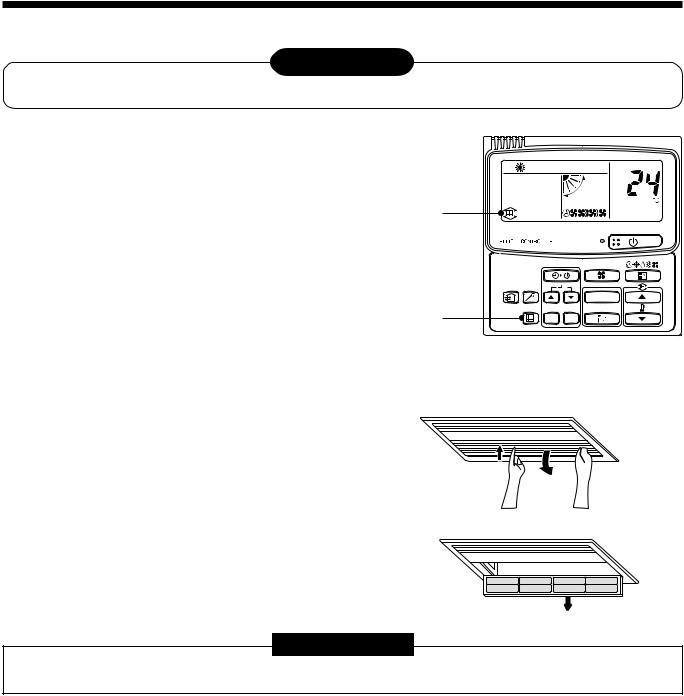
10 MAINTENANCE
For maintenance, be sure to turn off the main power switch.
 CAUTION
Do not handle the buttons with wet hands; otherwise an electric shock may be caused.
<Daily maintenance>
Cleaning of air filter
1 If [FILTER] is displayed on the remote controller, maintain the air filter.
2 Clogging of the air filter decreases cooling/ heating efficiency.
3 After cleaning, push  .
.
[FILTER] display disappears.
1,
2
3
CODE No.
UNIT
SET CL
[1-way Air Discharge Cassette Compact Type]
1 Push [PUSH] at the center and left/right of the air inlet port to open the air inlet port.
2 Take out the air filter by lifting up it once and then pull it downward.
REQUIREMENT
• Insert the air filter of 1-way Air Discharge Cassette Compact Type surely into the specified position.
26
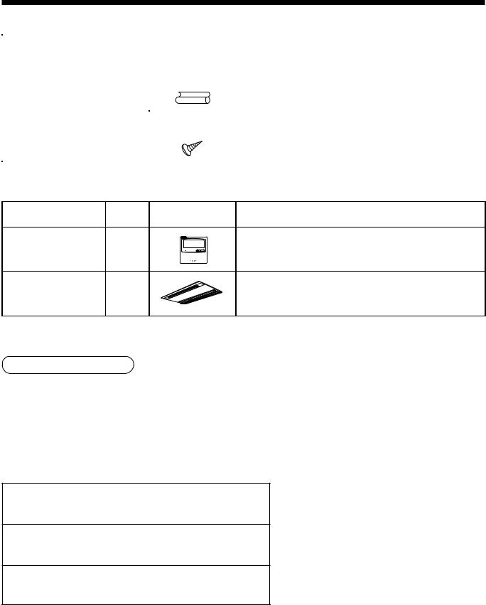
Pièces accessoires et pièces non fournies
H Piè ces accessoires
Nom de la pièce |
Quantité |
Forme |
Utilisation |
|
|
|
|
Manuel d’installation |
1 |
Ce manuel |
(Veillez à le remettre aux utilisateurs) |
|
|
|
|
Tube d’isolation thermique |
2 |
|
Pour l’isolation thermique des sections de raccordement des tuyaux |
|
|
|
|
Gabarit d’installation |
1 |
— |
Pour vérifier l’ouverture du plafond et la position de l’unité principale |
|
|
|
|
Vis de fixation du gabarit |
5 |
|
Fixation du gabarit d’installation |
|
|
|
|
<Piè ces vendues sé paré ment>
Nom de la pièce |
Quantité |
Forme |
Utilisation |
Télécommande avec fil |
1 |
|
Modèle : RBC-AMT21E |
standard |
|
||
|
|
|
|
Panneau pour plafond |
1 |
|
Modèle : RBC-UY135PG |
Tuyaux de ré frigé rant
•Le kit de tuyaux utilisé pour le réfrigérant traditionnel ne peut pas être utilisé.
•Utilisez un tuyau en cuivre de 0,8 mm ou plus d’épaisseur pour Ø 6.4, Ø 9.5, Ø 12.7.
•Les écrous évasés et l’évasement diffèrent également de ceux des tuyaux du réfrigérant traditionnel. Retirez l’écrou évasé fourni avec l’unité principale du climatiseur et utilisez-le.
H Piè ces non fournies
Tuyau de raccordement (côté liquide)
(6.4 mm (diam.), (diam.) épaisseur nominale 1/4 pouces (0.8 mm)
Tuyau de raccordement (côté gaz)
(12.7 mm (diam.), (diam.) épaisseur nominale 3/8 pouces (0.8 mm)
Cordon d’alimentation
Câble 3-fils 2.5 mm2, conformé ment au Plan 60245 IEC57
27
 Loading...