


 Loading...
Toshiba Personal Computer
TOSHIBA NB100
(PLL10X-XXXXX)
Maintenance Manual
TOSHIBA CORPORATION
S/ No
Libretto L100/L105/Satellite UX/TOSHIBA NB100 Maintenance Manual

Copyright
© 2008 by Toshiba Corporation. All rights reserved. Under the copyright laws, this manual cannot be reproduced in any form without the prior written permission of Toshiba. No patent liability is assumed with respect to the use of the information contained herein.
TOSHIBA NB100 Maintenance Manual
First edition Sep 2008
Disclaimer
The information presented in this manual has been reviewed and validated for accuracy. The included set of instructions and descriptions are accurate for the TOSHIBA NB100 at the time of this manual's production. However, succeeding computers and manuals are subject to change without notice. Therefore, Toshiba assumes no liability for damages incurred directly or indirectly from errors, omissions, or discrepancies between any succeeding product and this manual.
Trademarks
Intel and Pentium are registered trademarks of Intel Corporation.
IBM, IBM PC/XT, PC/AT, PS/2 and OS/2 are registered trademarks of IBM Corporation. Windows XP are registered trademarks of Microsoft Corporation.
Sound Blaster and Pro are trademarks of Creative Technology Ltd. UNIX is a registered trademark of X/Open Company Ltd. NetWare are registered trademarks of Novell, Inc.
All other properties are trademarks or registered trademarks of their respective holders.
ii |
TOSHIBA NB100 Maintenance Manual |
Preface
This maintenance manual describes how to perform hardware service maintenance for the Toshiba Personal Computer TOSHIBA NB100 , referred to as TOSHIBA NB100 in this manual.
The procedures described in this manual are intended to help service technicians isolate faulty Field Replaceable Units (FRUs) and replace them in the field.
SAFETY PRECAUTIONS
Four types of messages are used in this manual to bring important information to your attention. Each of these messages will be italicized and identified as shown below.
DANGER: “Danger” indicates the existence of a hazard that could result in death or serious bodily injury, if the safety instruction is not observed.
WARNING: “Warning” indicates the existence of a hazard that could result in bodily injury, if the safety instruction is not observed.
CAUTION: “Caution” indicates the existence of a hazard that could result in property damage, if the safety instruction is not observed.
NOTE: “Note” contains general information that relates to your safe maintenance service.
Improper repair of the computer may result in safety hazards. Toshiba requires service technicians and authorized dealers or service providers to ensure the following safety precautions are adhered to strictly.
Be sure to fasten screws securely with the right screwdriver. If a screw is not fully fastened, it could come loose, creating a danger of a short circuit, which could cause overheating, smoke or fire.
If you replace the battery pack, RTC battery or backup battery, be sure to use only the same model battery or an equivalent battery recommended by Toshiba. Installation of the wrong battery can cause the battery to explode.
TOSHIBA NB100 Maintenance Manual |
iii |

The manual is divided into the following parts:
Chapter 1 Hardware Overview describes the TOSHIBA NB100 system unit and each FRU.
Chapter 2 Troubleshooting Procedures explains how to diagnose and resolve FRU problems.
Chapter 3 Test and Diagnostics describes how to perform test and diagnostic operations for maintenance service.
Chapter 4 Replacement Procedures describes the removal and replacement of the FRUs.
Appendices The appendices describe the following:
Handling the LCD module
Board layout
Pin Assignments
Keyboard scan/character codes
Key layout
iv |
TOSHIBA NB100 Maintenance Manual |

Conventions
This manual uses the following formats to describe, identify, and highlight terms and operating procedures.
Acronyms
On the first appearance and whenever necessary for clarification acronyms are enclosed in parentheses following their definition. For example:
Read Only Memory (ROM)
Keys
Keys are used in the text to describe many operations. The key top symbol as it appears on the keyboard is printed in boldface type.
Key operation
Some operations require you to simultaneously use two or more keys. We identify such operations by the key top symbols separated by a plus (+) sign. For example, Ctrl + Pause (Break) means you must hold down Ctrl and at the same time press Pause (Break). If three keys are used, hold down the first two and at the same time press the third.
User input
Text that you are instructed to type in is shown in the boldface type below:
DISKCOPY A: B:
The display
Text generated by the XXXXX that appears on its display is presented in the type face below:
Format complete
System transferred
TOSHIBA NB100 Maintenance Manual |
v |

4 Replacement Procedures
Table of Contents
Chapter 1 |
Hardware Overview |
|
|
1.1 |
Features |
...................................................................................................................... |
5 |
1.2 |
System Unit .........................................................................................Components |
11 |
|
1.3 |
2.5-inch ...........................................................................................................HDD |
16 |
|
1.4 |
Solid State ...........................................................................................Drive (SSD) |
17 |
|
1.5 |
Power Supply ........................................................................................................... |
18 |
|
1.6 |
Batteries.................................................................................................................... |
|
19 |
|
1.6.1 ........................................................................................... |
Main Battery |
19 |
|
1.6.2 ....................................................................... |
Battery Charging Control |
19 |
|
1.6.3 ........................................................................................... |
RTC Battery |
20 |
Chapter 2 |
Troubleshooting |
|
||
2.1 |
Outline |
.................................................................................................................... |
|
2-1 |
2.2 |
Basic Flowchart...................................................................................................... |
2-2 |
||
2.3 |
Power Supply ......................................................................................................... |
|
2-6 |
|
|
Procedure 1 Power Icon Check........................................................................... |
2-6 |
||
|
Procedure 2 Connection Check........................................................................... |
2-8 |
||
|
Procedure 3 Replacement Check ........................................................................ |
2-8 |
||
2.4 |
System Board ......................................................................................................... |
|
2-9 |
|
|
Procedure ....................................................................3 |
Replacement Check |
2-10 |
|
2.5 |
HDD ..................................................................................................................... |
|
|
2-11 |
|
Procedure .............................................................................1 Message Check |
2-11 |
||
|
Procedure ......................................................................2 |
Partition Check |
2-11 |
|
|
Procedure ..........................................................................3 |
Format Check |
2-12 |
|
|
Procedure ...............................................................4 |
Test Program Check |
2-13 |
|
|
Procedure .............................5 |
Connector Check and Replacement Check |
2-14 |
|
2.6 |
Keyboard .............................................................................................................. |
|
2-15 |
|
|
Procedure ......................................................................1 Test Program Check |
2-15 |
||
TOSHIBA NB100 Maintenance Manual |
4-iii |

4 Replacement Procedures
|
Procedure 2 Connector Check and Replacement Check.................................... |
2-15 |
|||
2.7 |
Display |
................................................................................................................. |
|
|
2-16 |
|
Procedure 1 |
External Monitor Check ......................................................... |
|
2-16 |
|
|
Procedure 2 |
Test Program Check ............................................................... |
|
2-16 |
|
|
Procedure 3 |
Connector Check and Replacement Check............................. |
2-16 |
||
2.8 |
LAN...................................................................................................................... |
|
|
|
2-18 |
|
Procedure ...............................................................1 |
Test Program Check |
|
2-18 |
|
|
Procedure .............................2 |
Connector Check and Replacement Check |
2-18 |
||
2.9 |
Audio Test ............................................................................................................ |
|
|
2-18 |
|
|
Procedure ......................................................................1 Test Program Check |
|
2-19 |
||
|
Procedure ....................................2 Connector Check and Replacement Check |
2-19 |
|||
2.10 |
Cooling ....................................................................................................Module |
|
|
2-20 |
|
|
Procedure ...............................................................1 |
Test Program Check |
|
2-20 |
|
|
Procedure .............................2 |
Connector Check and Replacement Check |
2-20 |
||
Chapter 3 |
Diagnostic Programs |
|
|
||
3.1 |
General ..................................................................... |
|
|
Error! Bookmark not defined. |
|
3.2 |
Quick Start................................................................ |
|
Error! Bookmark not defined. |
||
|
3.2.1 .............................................. |
Quick Test |
Error! Bookmark not defined. |
||
|
3.2.2 ................................. |
Customization Test |
Error! Bookmark not defined. |
||
|
3.2.3 ............................. |
Keyboard Layout test |
Error! Bookmark not defined. |
||
|
3.2.4 ...................................... |
Audio Play Test |
Error! Bookmark not defined. |
||
|
3.2.5 ................................. |
Audio Record Test |
Error! Bookmark not defined. |
||
|
3.2.6 ............................................... |
DMI Read |
Error! Bookmark not defined. |
||
|
3.2.7 .............................................. |
DMI Write |
Error! Bookmark not defined. |
||
|
3.2.8 ................................ |
System Information |
Error! Bookmark not defined. |
||
|
3.2.9 .............................................. |
View Logs |
Error! Bookmark not defined. |
||
|
3.2.10 ................................... |
Exit to Free DOS |
Error! Bookmark not defined. |
||
|
3.2.11 ...... |
The Diagnostics Screen Explanation |
Error! Bookmark not defined. |
||
3.3 |
Options ..................................................................... |
|
|
Error! Bookmark not defined. |
|
|
3.3.1 ................................................ |
Overview |
Error! Bookmark not defined. |
||
|
3.3.2 ............ |
Batch Parameters Configuration |
Error! Bookmark not defined. |
||
4-iv |
TOSHIBA NB100 Maintenance Manual |

|
|
|
4 |
Replacement Procedure |
|
3.3.3 |
Item’s Parameters Configuration ........... |
Error! Bookmark not defined. |
|
|
3.3.4 |
Load Batch Parameters ........................... |
Error! Bookmark not defined. |
|
|
3.3.5 |
Save Batch Parameters ........................... |
Error! Bookmark not defined. |
|
|
3.3.6 |
LOG Parameters Setting ......................... |
Error! Bookmark not defined. |
|
|
3.3.7 |
Specify LOG Viewer .............................. |
Error! Bookmark not defined. |
|
|
3.3.8 |
Display LOG File ................................... |
Error! Bookmark not defined. |
|
|
3.3.9 |
LOG Viewer ........................................... |
Error! Bookmark not defined. |
|
|
3.3.10 |
LOG File Sample ................................... |
Error! Bookmark not defined. |
|
3.4 |
Subtests |
..................................................................... |
Error! Bookmark not defined. |
|
3.5 |
System Test .............................................................. |
Error! Bookmark not defined. |
||
3.6 |
Memory ............................................................Test |
Error! Bookmark not defined. |
||
3.7 |
Storage...................................................................... |
|
Error! Bookmark not defined. |
|
3.8 |
Video ........................................................................ |
|
Error! Bookmark not defined. |
|
3.9 |
Communication ........................................(COMM) |
Error! Bookmark not defined. |
||
3.10 |
Peripheral ................................................................. |
Error! Bookmark not defined. |
||
3.11 |
Error Codes .....................................and description |
Error! Bookmark not defined. |
||
3.12 |
Quick Test .................................................Item List |
Error! Bookmark not defined. |
||
Chapter 4 |
Replacement Procedures |
|
|
|
4.1 |
General ................................................................................................................... |
|
|
4-1 |
|
Safety ................................................................................................Precautions |
|
4-2 |
|
|
Before ................................................................................................You Begin |
|
4-4 |
|
|
Disassembly ......................................................................................Procedures |
|
4-5 |
|
|
Assembly ...........................................................................................Procedures |
|
4-5 |
|
|
Tools and ...........................................................................................Equipment |
|
4-6 |
|
|
Screw ....................................................................................Tightening Torque |
|
4-6 |
|
|
Colors .......................................................................................of Screw Shanks |
|
4-7 |
|
|
Symbols .........................................................of Screws on the Computer Body |
|
4-7 |
|
|
Symbol .................................................................................................examples |
|
4-7 |
|
|
Removing .................................................................................the Battery Pack |
|
4-8 |
|
|
Installing ...................................................................................the Battery Pack |
|
4-9 |
|
|
Removing .............................................................................the Momery Card |
|
4-10 |
|
iv |
TOSHIBA NB100 Maintenance Manual |

4 Replacement Procedures
|
Installing the Momery Card............................................................................... |
4-11 |
|
Removing the Optional Memory ....................................................................... |
4-12 |
|
Installing the Optional Memory......................................................................... |
4-13 |
4.2 |
Keyboard Cover and Keyboard............................................................................ |
4-14 |
|
Removing the Keyboard Cover and Keyboard.................................................. |
4-14 |
|
Installing the Keyboard Cover and Keyboard ................................................... |
4-16 |
4.3 |
Wireless LAN Card.............................................................................................. |
4-17 |
|
Removing the Wireless LAN Card .................................................................... |
4-17 |
|
Installing the Wireless LAN Card...................................................................... |
4-18 |
4.4 |
Display Assembly ..................................................................................................... |
4-19 |
|
Removing the Display Assembly....................................................................... |
4-19 |
|
Installing the Display Assembly ........................................................................ |
4-21 |
4.5 |
Top Cover............................................................................................................. |
4-22 |
|
Removing the Top Cover................................................................................... |
4-22 |
|
Installing the Top Cover .................................................................................... |
4-23 |
4.6 |
SSD/HDD and Fan ............................................................................................... |
4-24 |
|
Removing the SSD/HDD and Fan ..................................................................... |
4-24 |
|
Installing the SSD/HDD and Fan....................................................................... |
4-26 |
4.7 |
System Board,DC-IN,RJ45 Cable and Blue-Tooth Card..................................... |
4-27 |
|
Removing the System Board,DC-IN,RJ45 Cable and Blue-Tooth Card…....... 4-27 |
|
|
Installing the System Board,DC-IN,RJ45 Cable and Blue-Tooth Card.. .......... 4-29 |
|
4.8 |
Display Mask........................................................................................................ |
4-30 |
|
Removing the LCD Display Mask..................................................................... |
4-30 |
|
Installing the LCD Display Mask ...................................................................... |
4-32 |
4.9 |
LCD Modules....................................................................................................... |
4-33 |
|
Removing the LCD module .............................................................................. |
4-33 |
|
Installing the LCD Module ................................................................................ |
4-35 |
4.10 |
CCD board and Speakers ..................................................................................... |
4-36 |
|
Removing the CCD board and Speakers ........................................................... |
4-36 |
|
Installing the CCD board and Speakers............................................................. |
4-37 |
4.11 |
Touch Pad Board.................................................................................................. |
4-38 |
|
Removing the Touch Pad Board ........................................................................ |
4-38 |
4-iv |
TOSHIBA NB100 Maintenance Manual |

4 Replacement Procedure
Installing the Touch Pad Board ......................................................................... |
4-39 |
vi |
TOSHIBA NB100 Maintenance Manual |
4 Replacement Procedures
Appendices |
|
|
Appendix A |
Handling the LCD Module ........................................................................... |
A-1 |
Appendix B |
Board Layout ................................................................................................ |
B-1 |
Appendix C |
Pin Assignments............................................................................................ |
C-1 |
Appendix D |
Keyboard Scan/Character Codes .................................................................. |
D-1 |
Appendix E |
Key Layout..................................................................................................... |
E-1 |
4-iv |
TOSHIBA NB100 Maintenance Manual |

Chapter 1
Hardware Overview
TOSHIBA NB100 Maintenance Manual |
i |

1 Hardware Overview
ii |
TOSHIBA NB100 Maintenance Manual |

1 Hardware Overview
Chapter 1 |
Contents |
|
|
1.1 |
Features ......................................................................................................................... |
|
5 |
1.2 |
System Unit Components ........................................................................................... |
11 |
|
1.3 |
2.5-inch HDD.............................................................................................................. |
16 |
|
1.4 |
Solid State Drive (SSD).............................................................................................. |
17 |
|
1.5 |
Power Supply .............................................................................................................. |
18 |
|
1.6 |
Batteries ...................................................................................................................... |
|
19 |
|
1.6.1 |
Main Battery.......................................................................................... |
19 |
|
1.6.2 |
Battery Charging Control ...................................................................... |
19 |
|
1.6.3 |
RTC Battery .......................................................................................... |
20 |
TOSHIBA NB100 Maintenance Manual |
iii |

1 Hardware Overview
Figures |
|
Figure 1-1 ID Parts Description Placement |
...............................................................................8 |
Figure 1-2 Computer Block Diagram........................................................................................ |
9 |
Figure 1-3 System Board Configurations................................................................................ |
10 |
Figure 1-4 System Unit Block Diagram.................................................................................. |
11 |
Figure 1-5 SATA HDD ........................................................................................................... |
16 |
Figure 1-6 Solid state driver .................................................................................................... |
17 |
Table |
|
Table 1-1 HDD Specifications ................................................................................................ |
16 |
Table 1-2 SSD Specifications.................................................................................................. |
17 |
Table 1-3 Battery specifications.............................................................................................. |
19 |
Table 1-4 Quick/Normal charging time .................................................................................. |
19 |
iv |
TOSHIBA NB100 Maintenance Manual |

1.1 Features |
1 Hardware Overview |
1.1Features
The Toshiba Arizona is a B5 size notebook PC based on the ATOM processor, providing highspeed processing capabilities and advanced features. The computer employs a Lithium Ion battery that allows it to be battery-operated for a longer period of time. The display uses 8.9- inch WSGA LCD panel, at a resolution of 1280 by 600 pixels...
The computer has the following features.
Processor
The CPU is the ATOM Processor. Diamondville 1.6GHz
Host Bridge System Controller
System Controller: Intel 945GSE+ICH7-M
Graphics
Intel 945GSE integrated graphic.
Memory
The computer has one SO-DIMMs slot comes standard with DDRII-667/800MHz module. It supports PC2-5300/6400 and uses SO-DIMMs (DDRII SDRAM) driven at 1.8 V, accepting BTO/CTO for your memory requirements. It can incorporate up to 1 GB for 945GSE.
Using the following sizes of memory modules:
y512 MB (64M×16×4P)/667 MHZ
y1024 MB (64M×16×8P)/800 MHZ
Hard Disk Drive (HDD)
The computer accommodates 9.5 mm height HDD with following storage capacities:
y80 GB (9.5 mm thick) SATA (5,400rpm)
y120 GB (9.5 mm thick) SATA (5,400rpm)
TOSHIBA NB100 Maintenance Manual |
5 |

1 Hardware Overview |
1.1 Features |
y 160 GB (9.5 mm thick) SATA (5,400rpm) |
|
Solid-State Drive (SSD) |
|
The computer accommodates SSD with following storage capacities: |
|
y4 GB SATA
Display
The LCD displays available come with one of following types:
y8.9” WSGA LED backlight color display, resolution 1280×600
Keyboard
The keyboard has 11 kinds’ countries key.
Battery
The computer has a removable 4 Cell Lithium Ion battery pack.
Universal Serial Bus (USB) Ports
The computer has four USB 2.0 ports. It is supported to daisy-chain a maximum of 127 USB devices. The serial data transfer rate is 480 Mbps or 12 Mbps and 1.5 Mbps. These ports support PnP installation and hot plugging.
External Monitor Port
A 15-pin external monitor port is provided, through which the computer automatically recognizes an external VESA DDC 2B compatible monitor.
Multiple Digital Media Card Slot
This computer is equipped with Multiple Digital Media Card Slot that can accommodate SD/ Mini-SD/ Micro-SD/ SD-IO/ SDHC/ MS/ MS Pro/ MMC memory cards. This slot is for your memory card requirements to provide memory card read on your computer
Toshiba Pointing Device
Toshiba Pointing Device has one kind of Normal touchpad and one kind of touch pad.
6 |
TOSHIBA NB100 Maintenance Manual |

1.1 Features |
1 Hardware Overview |
Sound System
The ALC262 integrated audio controller supports multimedia. The sound system contains the following:
yStereo speakers
yHeadphone / SPDIF combo jack
yInternal microphone
yExternal microphone jack
LAN
The internal LAN board supports 10/100Mbit. It also supports Wake-up on LAN from S3/S4/S5 and PXE boot support. The LAN board has RJ45 jack to directly accommodate a LAN cable.
Wireless LAN
The internal Mini Card slot supports IEEE802.11bg. The Antenna has two dual band antennas.
Internal Camera (BTO)
The computer has an internal camera. The camera has VGA (fixed focus) for low end ID or 1.3Mpix resolution (fixed focus) for mainstream ID support.
TOSHIBA NB100 Maintenance Manual |
7 |

1 Hardware Overview |
1.1 Features |
Figures 1-1/1-2/1-3 and 1-4 show the computer and its system unit configuration, respectively.
Figure 1-1 ID Parts Description Placement
8 |
TOSHIBA NB100 Maintenance Manual |
1.1 Features |
1 Hardware Overview |
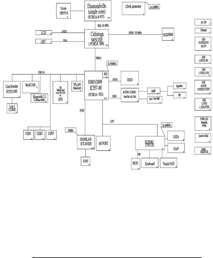
Figure 1-2 Computer Block Diagram
TOSHIBA NB100 Maintenance Manual |
9 |
1 Hardware Overview |
1.1 Features |
Figure 1-3 System Board Configurations
10 |
TOSHIBA NB100 Maintenance Manual |
1.2 System Unit Components |
1 Hardware Overview |
1.2System Unit Components
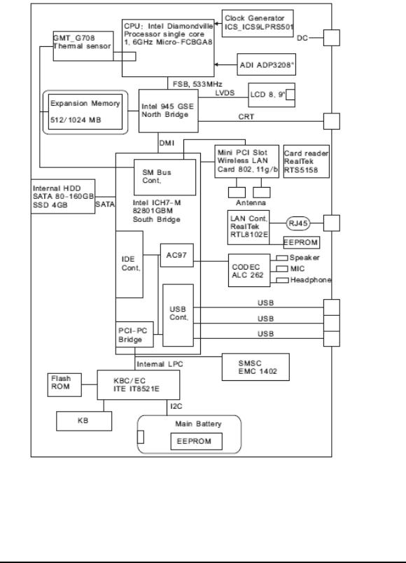
Figure 1-4 is Block Diagram of the System Unit.
Figure 1-4 System Unit Block Diagram
TOSHIBA NB100 Maintenance Manual |
11 |

1 Hardware Overview |
1.2 System Unit Components |
The system unit of the computer consists of the following components:
Processor: ATOM Processor.
yDiamondville (1.6GHz)
−Core speed: 1.6GHz/800MHz
−System bus: 400/533 MHz
−On-die level 2 cache: 512KB
Memory
Two expansion memory slots are provided. They can hold 512/1024MB expansion memory modules available as options to grow up to 1GB for 945GSE.
yPC2-5300/667MHz and PC2-6400/800MHz DDRII SDRAM supported
y512/1024 modules supported
−512 MB (32M x 16 x 8P)
−1024 MB (64M x 8 x 16P)
y1.8 volt operation
yNo parity bit
y64-bit data transfer
yRun at 400/533MHz
BIOS ROM (Flash EEPROM)
y8Mb x 1 chip (1024KB flash parts)
−NvStorage size : 128K
−NvStorage free space : 101K
−FV00 size : 624K
−FV00 free space : 49K
−FV01 size : 64K
−FV01 free space : 45K
−FV02 size : 36K
−FV02 free space : 4K
−FV03 size : 20K
−FV03 free space : 2K
−FV04 size : 72K
−FV04 free space : 15K
System Controllers
yNorth Bridge: Intel 945GSE
−CPU Interface and Control
12 |
TOSHIBA NB100 Maintenance Manual |

1.2 System Unit Components |
1 Hardware Overview |
−System Memory Support
−PCI Express* Graphics (PEG) Interface
−Integrated Display Interface Support
−Internal Graphics Features
−Direct Media Interface (DMI)
−Power Management
−Security and Manageability
−Serial ATA Interface
−ICH7-M Audio Control
ySouth Bridge: Intel ICH7-M
−Direct Media Interface (DMI)
−PCI Express* Interface
−Serial ATA (SATA) Controller
−Advanced Host Controller Interface (AHCI)
−Intel Matrix Storage Technology
−PCI Interface
−IDE Interface
−Low Pin Count (LPC) Interface
−Serial Peripheral Interface (SPI)
−Compatibility Modules
−Advanced Programmable Interrupt Controller (APIC)
−Universal Serial Bus (USB) Controller
−LAN Controller
−RTC
−GPIO
−Enhanced Power Management
−Manageability
−System Management Bus (SMBus 2.0)
−Intel High Definition Audio Controller
−Integrated FAN Speed Control
Card Bus Controller
yRTS5158
−SD/Mini SD/SD-IO/MS/MS Pro/MMC Card Controller
−PCI Bus interface
Audio Controller
Realtek ALC262 integrated audio controller supports multimedia. The sound system feature contains the following:
y 2 Stereo DACs support 16/20/24-bit PCM format for stereo audio playback.
TOSHIBA NB100 Maintenance Manual |
13 |

1 Hardware Overview |
1.2 System Unit Components |
y2 stereo ADCs support 16/20-bit PCM format for two stereo independent sound inputs.
y16/20/24-bit S/PDIF-OUT supports 44.1K/48K/88.2K/96K/192KHz sample rate.
yAll ADCs support 44.1K/48K/96KHZ sample rate.
y4 GPIOs (GPIO0/GPIO3 are digital GPIO shared with digital MIC interface, GPIO1/GPIO2 are analog) for customized applications.
yHigh quality analog differential CD input.
y2 jack detection pins each designed to detect up to 4 jacks.
ySupports hardware digital volume control for digital microphone input.
ySupports external PCBEEP input and built-in digital BEEP generator.
−
KBC/EC (Keyboard Controller/Embedded Controller)
A single ITE8521E-L chip is used to serve as KBC/ EC and Super IO.
y KBC
−Scan controller function
−Interface controller function
y EC
−Power supply sequence control
−Overheat shutdown support
−LED control
−Beep control
−Device ON/OFF
−Cooling fan speed control
−Universal I/O port
−Battery capacity check
−Flash memory reprogramming function
−EC access interface
−I2C communication control
Battery EEPROM
y24C02 equivalent (128 words x 16 bits, I2C interface) integrated in battery pack.
−Storing records of battery use
Clock Generator
yICS9LPRS501
−Generating the clock signal required for the system.
14 |
TOSHIBA NB100 Maintenance Manual |

1.2 System Unit Components |
1 Hardware Overview |
LAN Controller
yRealtek 8101E 10/100Mbit
−IEEE 802.3 10BASE-T/100BASE-TX compliant physical layer interface
−IEEE 802.3u Auto-Negotiation support
−Digital Adaptive Equalization control
−10BASE-T auto-polarity correction
−LAN Connect interface
−Automatic detection of “unplugged mode”
−Remote boot (PXE 2.1)
−Smart power down when link is not detected
Wireless LAN Controller
ySupport following mini PCI wireless LAN cards
−IEEE 802.11bg
yData Rate
−IEEE 802.11bg: Standard 54M bps
yFrequency Channel
−IEEE802.11bg: 2.4GHz
TOSHIBA NB100 Maintenance Manual |
15 |
1 Hardware Overview |
1.3 2.5-inch HDD |
1.32.5-inch HDD
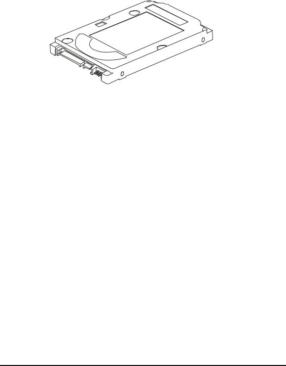
The computer contains an extremely low-profile and lightweight, high-performance HDD. The HDD incorporates 9.5 mm height magnetic disk and mini-Winchester type magnetic heads. The HDD interface conforms to Serial ATA. Storage capacities supported are 80, 120 and 160 GB.
The HDD is shown in Figure 1-5 and some of its specifications are listed in Table 1-1.
Figure 1-5 SATA HDD
Table 1-1 HDD Specifications
Item |
|
Specifications |
|
|
|
|
|
Capacity (GB) |
80 GB |
120 GB |
160 GB |
|
|
|
|
Rotational Speed (RPM) |
5400 rpm |
5400 rpm |
5400 rpm |
|
|
|
|
Height |
9.5 mm |
9.5 mm |
9.5 mm |
|
|
|
|
User Data Sectors |
156,301,488 |
234,442,648 |
312,581,808 |
|
|
|
|
Bytes / Sector |
512 |
512 |
512 |
|
|
|
|
16 |
TOSHIBA NB100 Maintenance Manual |
1.4 Solid State Driver (SSD) |
1 Hardware Overview |
1.4Solid State Drive (SSD)
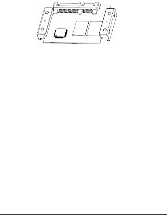
SATA Flash Drive (SAFD) series is a SATA Solid State Drive (SSD) that is more rugged, reliable and power-efficient compared to a mechanical hard drive. With no moving parts, the SAFD Series SSD is designed for use in rugged laptops, military devices, thin clients, Point of Sale (POS) terminals, telecom, medical instruments, surveillance systems and industrial PCs. The SSD is shown in Figure 1-6 and some of its specifications are listed in Table 1-2.
Figure 1-6 Solid state driver
Table 1-2 SSD Specifications
Item |
Specifications |
|
|
Capacity (GB) |
4 GB |
|
|
Total bytes |
4,096,253,952 |
|
|
Cylinders |
7937 |
|
|
Head |
16 |
|
|
Sector |
63 |
|
|
Max LBA |
8,000,496 |
|
|
TOSHIBA NB100 Maintenance Manual |
17 |

1 Hardware Overview |
1.5 Power Supply |
1.5Power Supply
The power supply unit provides many different voltages for the system board and performs the following functions:
1. Power input monitor
yChecks whether the DC power supply (AC adapter) is connected to the computer.
yChecks whether the battery pack is connected to the computer.
yMonitors the DC power supply input voltage (AC Adapter output voltage).
2.Power supply's internal control
yTurns on and off the battery pack charging power supply.
yIssues a charging current instruction to the PWM control IC of the battery pack charging power supply.
yControls the supply of DC power supply input (AC Adapter output) to the power supply unit.
yControls the supply of power to the system block (load/logic circuit side).
yControls forced shutdown if the power supply malfunctions.
3.Logic circuit control
yInstructs the gate array to enable/disable tuning the power on.
yControls power-on/off operation.
4.Status display
yTurns on the Power LED (in Green).
yBattery indicator (in Green).
5.External interface
yPerforms communication through the I2C bus (via the internal EC/KBC).
yTransfers the power supply operation mode.
6.Output monitor
yMonitors the voltage output to the system block (load/logic circuit side).
yMonitors the voltage, over voltage, input/output current of the battery pack.
yMonitors the internal temperature of the battery pack.
yMonitors the supply voltage from the AC adapter.
18 |
TOSHIBA NB100 Maintenance Manual |

1.6 5BBatteries |
1 Hardware Overview |
1.6Batteries
The computer has the following three types of batteries:
Main Battery Pack
Real Time Clock (RTC) Battery
Table 1-5 lists the specifications of these batteries.
Table 1-3 Battery specifications
Battery Type |
Material |
Output voltage |
Capacity |
||
|
|
|
|
|
|
Main Battery Pack |
4 Cell |
Lithium Ion |
7.4 V |
4000 mAh |
|
|
|
|
|
||
4 Cell |
Lithium Ion |
7.4 V |
5200 mAh |
||
|
|||||
|
|
|
|
|
|
RTC Battery |
Lithium Ion |
3.0 V |
18 mAh |
||
|
|
|
|
|
|
1.6.1Main Battery
The main battery pack serves as the computer's main power source when the AC adapter is not attached. The main battery maintains the state of the computer so that it can resume it.
1.6.2Battery Charging Control
Battery charging is controlled by ITE IT8512E. When the AC adapter and battery pack are attached to the computer, the IT8512E controls the charge on/off state and detects a full charge.
Battery Charge
When the AC adapter is attached, the battery is charged by off-state charge when the system is powered off or by on-state charge when it is powered on.
State |
|
Charge Time |
|
|
|
|
|
Off-State Charge |
4 Cell |
|
About 4 hours max |
|
|
|
|
On-State Charge |
4 Cell |
|
About 4~10 hours max |
|
|
|
|
Table 1-4 Quick/Normal charging time
Libretto L100 Maintenance Manual |
19 |
Loading...