


File No. 960-140
Copyright
©1998 by Toshiba Corporation. All rights reserved. Under the copyright laws, this manual cannot be reproduced in any form without the prior written permission of Toshiba. No patent liability is assumed with respect to the use of the information contained herein.
Toshiba Libretto 100CT Maintenance Manual
First edition February 1998
Disclaimer
The information contained in this manual is subject to change without notice.
Toshiba Corporation and Toshiba America Information Systems, Inc., assume no liability for damages incurred directly or indirectly from errors, omissions, or discrepancies in connection with the furnishing, performance, or use of this material.
Trademarks
IBM is a registered trademark, and PC/AT, PS/2 and OS/2 are trademarks of IBM Corporation. MS-DOS and Windows are registered trademarks of Microsoft Corporation.
Intel and Pentium are registered trademarks, and MMX is a trademark of Intel Corporation. Lotus is a registered trademark of Lotus Development Corporation.
Novell and NetWare are registered trademarks of Novell, Inc. UNIX is a registered trademark of X/Open Company Ltd.
Sound Blaster and Pro are trademarks of Creative Technology Ltd.
Centronics is a registered trademark of Centronics Data Computer Corporation.
All other properties are trademarks or registered trademarks of their respective holders.
ii
File No. 960-140
Preface
This maintenance manual describes how to perform hardware service maintenance for the Toshiba Personal Computer Libretto 100CT.
The procedures described in this manual are intended to help service technicians isolate faulty Field Replaceable Units (FRUs) and replace them in the field.
SAFETY PRECAUTIONS
Four types of messages are used in this manual to bring important information to your attention. Each of these messages will be italicized and identified as shown below.
DANGER: “Danger” indicates the existence of a hazard that could result in death or serious injury if the safety instruction is not observed.
WARNING: “Warning” indicates the existence of a hazard that could result in bodily injury if the safety instruction is not observed.
CAUTION: “Caution” indicates the existence of a hazard that could result in property damage if the safety instruction is not observed.
NOTE: A Note contains general information that relates to your safe maintenance services.
Improper repair of the computer may result in safety hazards. Toshiba requires service technicians and authorized dealers or service providers to ensure the following safety precautions are adhered to strictly.
Be sure to fasten screws securely with the right screwdriver. If a screw is not fully fastened, it could loosen and create a short circuit, which could cause overheating, smoke, or fire.
If you replace the battery pack, RTC battery, or backup battery, be sure to use only the same model battery or an equivalent battery recommended by Toshiba. Installation of the wrong battery can cause the battery to explode.
iii

File No. 960-140
The manual is divided into the following parts:
Chapter 1 Hardware Overview describes the system unit and each FRU.
Chapter 2 Troubleshooting Procedures explains how to diagnose and resolve FRU problems.
Chapter 3 Tests and Diagnostics describes how to perform test and diagnostic operations for maintenance service.
Chapter 4 Replacement Procedures describes the removal and replacement of the FRUs.
Appendices The eight appendices describe the following:
Handling the LCD module
Board layout
Pin assignments
Keyboard scan/character codes
Key layout
Wiring diagrams
BIOS Rewrite Procedures
Reliability
iv

File No. 960-140
Conventions
This manual uses the following formats to describe, identify, and highlight terms and operating procedures.
Acronyms
On the first appearance and whenever necessary for clarification, acronyms are enclosed in parentheses following their definition. For example:
Read Only Memory (ROM)
Keys
Keys are used in the text to describe many operations. The keytop symbol, as it appears on the keyboard, is printed in boldface type.
Key operation
Some operations require you to simultaneously use two or more keys. We identify such operations by the keytop symbols separated by a plus (+) sign. For example,Ctrl + Pause (Break) means you must hold down Ctrl and at the same time press Pause (Break). If three keys are used, hold down the first two and at the same time press the third.
User input
Text that you are instructed to type in is shown in the boldface type below:
DISKCOPY A: B:
The display
Text generated by the computer that appears on its display is presented in the typeface below:
Format complete
System transferred
v

File No. 960-140
Table of Contents
Chapter 1 |
Hardware Overview |
|
|
1.1 |
Features.................................................................................................................. |
1-1 |
|
1.2 |
System Unit Block Diagram.................................................................................... |
1-5 |
|
1.3 |
3.5-inch External FDD............................................................................................ |
1-9 |
|
1.4 |
2.5-inch Hard Disk Drive...................................................................................... |
1-10 |
|
1.5 |
Keyboard.............................................................................................................. |
1-11 |
|
1.6 |
TFT Color LCD.................................................................................................... |
1-12 |
|
1.7 |
Power Supply ....................................................................................................... |
1-14 |
|
1.8 |
Batteries ............................................................................................................... |
1-16 |
|
Chapter 2 |
Troubleshooting Procedures |
|
|
2.1 |
Troubleshooting...................................................................................................... |
2-1 |
|
2.2 |
Troubleshooting Flowchart..................................................................................... |
2-2 |
|
2.3 |
Power Supply Troubleshooting............................................................................... |
2-6 |
|
2.4 |
System Board Troubleshooting............................................................................. |
2-14 |
|
2.5 |
FDD Troubleshooting........................................................................................... |
2-25 |
|
2.6 |
HDD Troubleshooting .......................................................................................... |
2-28 |
|
2.7 |
Keyboard Troubleshooting.................................................................................... |
2-34 |
|
2.8 |
Pointing Device Troubleshooting.......................................................................... |
2-36 |
|
2.9 |
Display Troubleshooting....................................................................................... |
2-37 |
|
Chapter 3 |
Tests and Diagnostics |
|
|
3.1 |
The Diagnostic Test................................................................................................ |
3-1 |
|
3.2 |
Executing the Diagnostic Test................................................................................. |
3-3 |
|
3.3 |
Subtest Names........................................................................................................ |
3-7 |
|
3.4 |
System Test............................................................................................................ |
3-9 |
|
3.5 |
Memory Test ........................................................................................................ |
3-10 |
|
3.6 |
Keyboard Test ...................................................................................................... |
3-12 |
|
vi

|
|
|
File No. 960-140 |
3.7 |
Display Test.......................................................................................................... |
3-16 |
|
3.8 |
Floppy Disk Test .................................................................................................. |
3-20 |
|
3.9 |
Printer Test........................................................................................................... |
3-22 |
|
3.10 |
Async Test............................................................................................................ |
3-24 |
|
3.11 |
Hard Disk Test ..................................................................................................... |
3-26 |
|
3.12 |
Real Timer Test .................................................................................................... |
3-30 |
|
3.13 |
NDP Test ............................................................................................................. |
3-32 |
|
3.14 |
Expansion Test ..................................................................................................... |
3-33 |
|
3.15 |
Sound Test ........................................................................................................... |
3-35 |
|
3.16 |
Error Code and Error Status Names...................................................................... |
3-36 |
|
3.17 |
Hard Disk Test Detail Status................................................................................. |
3-39 |
|
3.18 |
Hard Disk Format................................................................................................. |
3-41 |
|
3.19 |
Head Cleaning ...................................................................................................... |
3-46 |
|
3.20 |
Log Utilities.......................................................................................................... |
3-47 |
|
3.21 |
Running Test ........................................................................................................ |
3-49 |
|
3.22 |
Floppy Disk Drive Utilities.................................................................................... |
3-51 |
|
3.23 |
System Configuration............................................................................................ |
3-56 |
|
3.24 |
SETUP................................................................................................................. |
3-58 |
|
Chapter 4 |
Replacement Procedures |
|
|
4.1 |
Overview................................................................................................................ |
4-1 |
|
4.2 |
HDD....................................................................................................................... |
|
4-8 |
4.3 |
Optional Memory Module..................................................................................... |
4-10 |
|
4.4 |
Keyboard.............................................................................................................. |
4-12 |
|
4.5 |
Display Assembly.................................................................................................. |
4-13 |
|
4.6 |
RTC Battery......................................................................................................... |
4-17 |
|
4.7 |
System Board, Heat Sink and PC Card Slot.......................................................... |
4-18 |
|
4.8 |
Display Mask........................................................................................................ |
4-20 |
|
4.9 |
FL Inverter Board................................................................................................. |
4-22 |
|
4.10 |
LCD Module ........................................................................................................ |
4-24 |
|
4.11 |
Speaker, Power Switch Board and AccuPoint Board............................................. |
4-27 |
|
4.12 |
LCD Flexible Cable and Microphone..................................................................... |
4-30 |
|
vii

File No. 960-140 |
|
|
4.13 I/O Adapter Board................................................................................................ |
4-35 |
|
Appendices |
|
|
Appendix A |
Handling the LCD Module ......................................................................... |
A-1 |
Appendix B |
Board Layout............................................................................................. |
B-1 |
Appendix C |
Pin Assignments......................................................................................... |
C-1 |
Appendix D |
Keyboard Scan/Character Codes ................................................................ |
D-1 |
Appendix E |
Key Layout ................................................................................................ |
E-1 |
Appendix F |
Wiring Diagrams ......................................................................................... |
F-1 |
Appendix G |
BIOS Rewrite Procedures .......................................................................... |
G-1 |
Appendix H |
Reliability................................................................................................... |
H-1 |
viii

File No. 960-140
Chapter 1
Hardware Overview

File No. 960-140
1-ii

|
|
|
File No. 960-140 |
|
|
|
|
Chapter 1 |
Contents |
|
|
1.1 |
Features.................................................................................................................. |
|
1-1 |
1.2 |
System Unit Block Diagram.................................................................................... |
1-5 |
|
1.3 |
3.5-inch External FDD............................................................................................ |
1-9 |
|
1.4 |
2.5-inch Hard Disk Drive...................................................................................... |
1-10 |
|
1.5 |
Keyboard.............................................................................................................. |
|
1-11 |
1.6 |
TFT Color LCD.................................................................................................... |
1-12 |
|
|
1.6.1 |
TFT Color LCD Module.................................................................. |
1-12 |
|
1.6.2 |
FL Inverter Board ............................................................................ |
1-13 |
1.7 |
Power Supply ....................................................................................................... |
1-14 |
|
1.8 |
Batteries ............................................................................................................... |
|
1-16 |
|
1.8.1 |
Main Battery.................................................................................... |
1-16 |
|
1.8.2 |
Battery Icon..................................................................................... |
1-16 |
|
1.8.3 |
Battery Charging Control................................................................. |
1-17 |
|
1.8.4 |
RTC Battery .................................................................................... |
1-17 |
Figures |
|
|
|
Figure 1-1 Front of the computer........................................................................................ |
1-4 |
||
Figure 1-2 System unit configuration.................................................................................. |
1-4 |
||
Figure 1-3 System unit block diagram................................................................................. |
1-5 |
||
Figure 1-4 3.5-inch FDD ................................................................................................... |
1-9 |
||
Figure 1-5 2.5-inch HDD................................................................................................. |
1-10 |
||
Figure 1-6 Keyboard ....................................................................................................... |
1-11 |
||
Figure 1-7 TFT color LCD.............................................................................................. |
1-12 |
||
1-iii
File No. 960-140
Tables |
|
|
Table 1-1 |
3.5-inch FDD specifications............................................................................... |
1-9 |
Table 1-2 |
2.5-inch HDD specifications.............................................................................. |
1-9 |
Table 1-3 |
LCD specifications........................................................................................... |
1-12 |
Table 1-4 |
FL inverter board specifications....................................................................... |
1-13 |
Table 1-5 |
Power supply board output rating.................................................................... |
1-15 |
Table 1-6 Battery specifications........................................................................................ |
1-16 |
|
Table 1-7 Time required for quick charges........................................................................ |
1-17 |
|
Table 1-8 |
RTC battery charging/data preservation time................................................... |
1-17 |
1-iv

File No. 960-140
1 Features
1.1Features
The computer uses Toshiba's advanced Large Scale Integration (LSI), and Complementary Metal-Oxide Semiconductor (CMOS) technology extensively to provide compact size, minimum weight, low power usage and high reliability. This computer incorporates the following features and benefits:
Microprocessor
The computer is equipped with an Intel® Pentium® processor with
MMXä Technology that operates at 166MHz and 1.8/2.5 volts.
Memory
The computer comes with 32MB of Extend Data Out (EDO) DRAM.
HDD
The computer has a 2.5-inch HDD with a capacity of 2.1GB HDD or 3.2GB HDD.
Display
The computer has a 7.1-inch color, Thin Film Transistor (TFT) Liquid Crystal Display (LCD), that enables display up to 256K colors at a resolution 800 x 480 pixels.
A video controller and 2MB of VRAM enable an external monitor to display 16M colors at a resolution of 800 x 600 pixels or 64K colors at a resolution of 1024 x 768 pixels.
Keyboard
An-easy-to-use 80/82-key keyboard provides a numeric keypad overlay for fast numeric data entry or for cursor and page control. The keyboard also includes two keys that have special functions in Microsoft® Windows® 95. It supports software that uses a 101or 102-key enhanced keyboard.
Batteries
The computer has two batteries a Lithium-Ion main battery pack and RTC battery that backs up the Real Time Clock and CMOS memory.
Expansion memory slot
An optional 32MB memory module can be installed in the memory slot.

File No. 960-140
Universal Serial Bus (USB)
The USB enables daisy-chain connection of up to 127 USB-equipped devices and 12Mbps serial data transfer. It is designed for easy configuration by a PnP operating system and provides hot insertion/ejection capability. The USB port is only on the Enhanced Port Replicator.
External monitor port
The port is available only on the I/O adapter and enables connection of an external SVGA compatible monitor.
PC card slot
A PC card slot accommodates two 5mm cards (Type II) or one 10.5mm (Type III) card, which support the PC card Standard. These slots support an external FDD,
16-bit PC cards and CardBus PC cards (32 bit) as well as the Zoomed Video (ZV) port cards, which are dedicated to high-performance video data transfer such as MPEG video play back.
AccuPoint
This pointer control stick, located in the right of the display panel, provides convenient control of the cursor without requiring desk space for a mouse.
Docking interface
A 140-pin, docking interface port enables connection of the I/O adapter or an optional Enhanced Port Replicator.
The Enhanced Port Replicator has two additional PC card slots that one accommodates a 10.5mm card (Type III) and one accommodates a 5mm card (Type II). These slots support CardBus PC card. The Enhanced Port Replicator also has PS/2ä mouse, PS/2 compatible keyboard, USB, parallel, serial and external monitor ports.
Infrared port
The infrared port is compatible with Fast InfraRed (FIR) standards enabling wireless 4Mbps data transfer with Infrared Data Association (IrDA) 1.1 compatible devices.
Sound system
A Sound Blasterä Proä and Windows Sound System compatible sound system gives the computer multimedia capability. The sound system is equipped with speaker, microphone and stereo headphone jack.

File No. 960-140
External FDD
A 3.5-inch external FDD is connected to the PC card slot and accommodates both 2HD (1.44MB) and 2DD (720KB) disks.

File No. 960-140
The computer is shown in Figure 1-1. The system unit configuration is shown in Figure 1- 2.
Figure 1-1 Front of the computer
Figure 1-2 System unit configuration
File No. 960-140
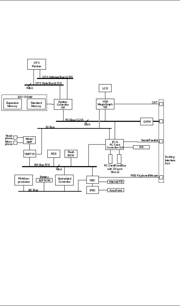
1.2System Unit Block Diagram
Figure 1-3 is a block diagram of the system unit.
Figure 1-3 System unit block diagram

File No. 960-140
The system unit is composed of the following major components:
Intel Pentium processor
Intel 166MHz Pentium processor with MMX Technology.
The math co-processor and 32KB cache memory are integrated into the Pentium.
Standard RAM
∙32 MB, four 4M x 16-bit EDO DRAM chips
∙3.3 volt operation
∙No parity bit
∙Access time 60 ns
∙Data transfer is 64-bit width
BIOS ROM (Flash EEPROM)
∙512 KB, one 512K x 8-bit chip
−256 KB are used for system BIOS
−64 KB are used for VGA-BIOS
−8 KB are used for plug and play data area
−8 KB are used for password security
−16 KB are used for boot strap
−288 KB are reserved
∙5 volt operation
∙Access time 120 ns
∙Data transfer is 8-bit width
Optional memory
One expansion memory slot is available for 32MB memory modules. The 32MB memory modules consist of four 4M x 16-bit EDO DRAM chips.
∙3.3 volt operation
∙No parity bit
∙Access time 60 ns
∙Data transfer is 64-bit width

File No. 960-140
System Controller Gate Array
∙This gate array has the following functions:
−CPU interface/control
−DRAM control
−PCI master/slave interface
−Write buffer (CPU-DRAM, CPU-PCI, PCI-DRAM)
−Prefetch buffer (CPU-PCI, PCI-DRAM)
−Mobile-PC/PCI support DMA function
−Serial interrupt function
−Power management control
−Suspend/resume control
−CPU stop clock function
−PCI clock stop function
−ACPI support function
I/O & PC Card Controller Gate Array
∙This gate array has the following functions:
− One UARTs 16550A equivalent (One SIO is used for SIR.)
−One parallel port control supported ECP
−mini ISA bus control
−PCI bus front end control
−PC card control
−ZV-port support
−CardBus control
−FIR function
−Universal I/O port
−Beep volume
−Speaker control
−RTC One T9934 chip is used
Video Controller
∙The NeoMagic NM2160 chip is used. The Video controller incorporates 2MB of video memory using a 128-bit data path.
Keyboard Controller (KBC)
∙One M38813S chip is used. This KBC includes the keyboard scan controller and keyboard interface controller. The KBC controls the internal keyboard, external keyboard, AccuPoint and PS/2 mouse.
AccuPoint Controller (IPSC)
∙One EMEP 010B chip is used.
∙This controller provides simultaneous control of the Pointing Device.

File No. 960-140
Sound Controller
∙One OPL3-SA3 is used.
∙The OPL3-SA3 incorporates OPL3 FM synthesizer, Digital Analog Converter (DAC) and MPU401 MIDI interface.
File No. 960-140
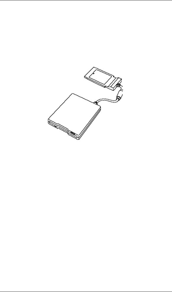
1.33.5-inch External FDD
The 3.5inch external FDD is a thin, high performance reliable drive that supports 720KB (formatted) 2DD and 1.44MB (formatted) 2HD disks. The FDD can be connected to the PC card slot.
The FDD is shown in Figure 1-4. The specifications for the FDD are listed in Table 1-1.
Figure 1-4 3.5-inch FDD
Table 1-1 3.5-inch FDD specifications
Item |
2-MB mode |
1-MB mode |
|
|
|
Storage capacity (KB) |
|
|
Unformatted |
2,000 |
1,000 |
Formatted |
1,440 |
720 |
|
|
|
Number of heads |
2 |
2 |
|
|
|
Number of cylinders |
80 |
80 |
|
|
|
Access time (ms) |
|
|
Track to track |
3 |
3 |
Average |
181 |
181 |
Head settling time |
15 |
15 |
|
|
|
Recording track density (tpi) |
135 |
135 |
|
|
|
Data transfer rate (Kbps) |
500 |
250 |
|
|
|
Rotation speed (rpm) |
300 |
300 |
|
|
|
Recording method |
Modified Frequency Modulation (MFM) |
|
|
|
|
File No. 960-140
1.42.5-inch Hard Disk Drive
The removable HDD is a random access non-volatile storage device. It has a nonremovable 2.5-inch magnetic disk and mini-Winchester type magnetic heads.
The computer supports 2.1GB HDD or 3.2GB HDD.
The HDD is shown in Figure 1-5. Specifications are listed in Table 1-2.
Figure 1-5 2.5-inch HDD
Table 1-2 2.5-inch HDD specifications
Items |
IBM DYKA-22160 |
IBM DYKA-23240 |
|
|
|
Formatted capacity (bytes) |
2,167,603,200 |
3,253,469,184 |
|
|
|
Logical cylinders |
4,200 |
6,304 |
|
|
|
Logical heads |
16 |
16 |
|
|
|
Logical sectors |
63 |
63 |
|
|
|
Bytes per sector |
512 |
512 |
|
|
|
Rotation speed (rpm) |
4,200 |
4,200 |
|
|
|
Recording method |
8-9 RLL |
8-9 RLL |
|
|
|
File No. 960-140
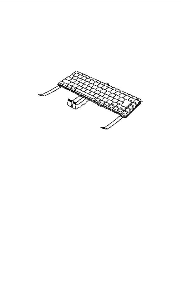
1.5Keyboard
The 84-(USA) or 86-(European) key keyboard is mounted on the system unit. The keyboard is connected to the keyboard controller on the system board through a 24-pin flat cable. The keyboard is shown in Figure 1-6.
See Appendix E for optional keyboard configurations.
Figure 1-6 Keyboard
File No. 960-140
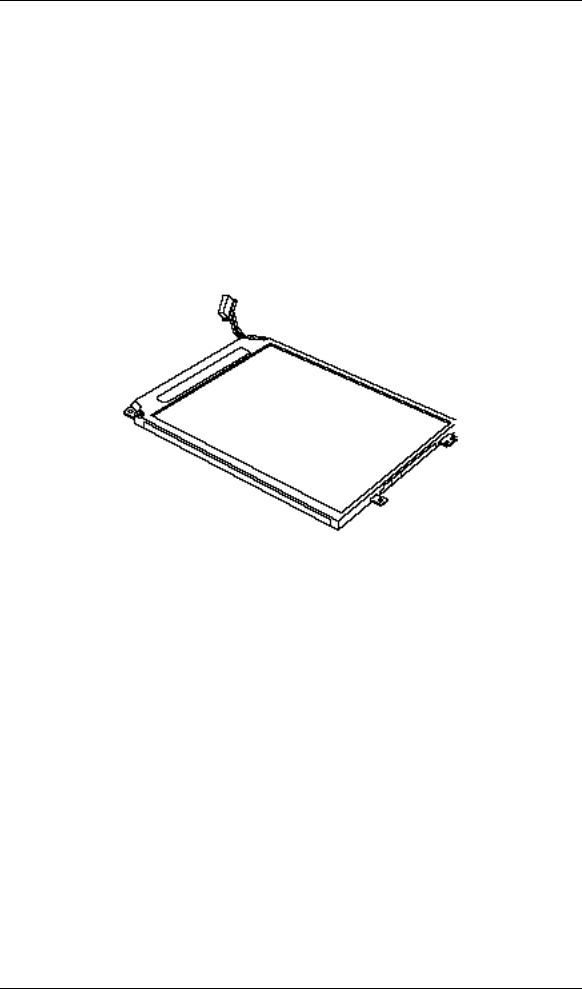
1.6TFT Color LCD
The display panel contains a TFT color LCD module, a fluorescent lamp (FL) andan FL inverter board.
1.6.1 TFT Color LCD Module
The LCD enables display of up to 256K colors at a resolution 800 x 480 pixels. The LCD is shown in Figure 1-7. Specifications are listed in Table 1-3.
Figure 1-7 TFT color LCD
Table 1-3 |
LCD specifications |
|
|
|
|
Items |
|
Specifications |
|
|
|
Number of Pixels (pixels) |
|
800x480 |
|
|
|
Dot pitch (mm) |
|
0.192x0.192 |
|
|
|
Display area (mm) |
|
153.6(H)x92.16(V) |
|
|
|
Contrast |
|
1:150 (Typ) |
|
|
|

File No. 960-140
1.6.2 FL Inverter Board
The FL inverter board supplies high frequency current to light the LCD’s Fluorescent Lamp.
Specifications for the FL inverter are listed in Table 1-4.
Table 1-4 FL inverter board specifications
Item |
|
Specifications |
|
|
|
||
|
|
|
|
|
|
|
|
Input |
Voltage |
(V) |
|
|
5 |
|
|
|
Power |
(W) |
|
|
2.3 |
|
|
|
|
|
|
|
|
|
|
Output |
Voltage |
(Vrms) |
|
800 |
|
|
|
|
Current |
(mA) |
|
|
2.0 to 3.5* |
|
|
|
|
|
|
|
|
|
|
*NOTE: The FL currents at power on are: |
|
|
|
|
|
||
Level 3 : 3.5mA |
Level 2 : 2.9mA |
Level 1 : 2.6mA |
Level 0 : 2.0mA |
||||

File No. 960-140
1.7Power Supply
The power supply supplies ten kinds of voltages to the system board, has one microprocessor and it operates at 4MHz. It performs the following functions:
1.Determines if the AC adapter or battery is connected to the computer.
2.Detects DC output and circuit malfunctions.
3.Controls the battery icon, and DC IN icon.
4.Turns the battery charging system on and off and detects a fully charged battery.
5.Determines if the power can be turned on and off.
6.Provides more accurate detection of a low battery.
7.Calculates the remaining battery capacity.
The embedded controller operates at 2MHz and has the following functions:
1.Controls ACPI in Windows 98.
2.Monitors the computer’s temperature.
3.Controls power supply to the docking port.
4.General purpose port.

File No. 960-140
The power supply output rating is specified in Table 1-5.
Table 1-5 |
Power supply board output rating |
|
|
||
|
|
|
|
|
|
|
|
|
Power supplied Yes/No |
||
|
|
|
|
|
|
Use |
Name |
Voltage(V) |
Suspend |
Power off |
No battery |
|
|
|
|
|
|
CPU |
+1.8V |
1.8 |
NO |
NO |
NO |
|
|
|
|
|
|
CPU, CLKGEN, System |
+2.5V |
2.5 |
NO |
NO |
NO |
Controller GA |
|
|
|
|
|
|
|
|
|
|
|
CLKGEN |
+3.3V |
3.3 |
NO |
NO |
NO |
|
|
|
|
|
|
System Controller GA, PC |
B3V |
3.3 |
YES |
NO |
NO |
Card Slot, VGA Controller, |
|
|
|
|
|
I/O & PC Card Controller |
|
|
|
|
|
GA, DRAM |
|
|
|
|
|
|
|
|
|
|
|
VGA Controller, PC Card |
B5V |
5.0 |
YES |
NO |
NO |
Slot |
|
|
|
|
|
|
|
|
|
|
|
Flash Memory, KBC, IPSC, |
VCC |
5.0 |
NO |
NO |
NO |
LCD Panel, HDD, LEDs, |
|
|
|
|
|
Sound, E2PROM,GA |
|
|
|
|
|
|
|
|
|
|
|
KB/Mouse Port |
IFVCC |
5.0 |
NO |
NO |
NO |
|
|
|
|
|
|
PSC |
MCV |
5.0 |
YES |
YES |
NO |
|
|
|
|
|
|
Embedded Controller |
S5V |
5.0 |
YES |
YES |
NO |
|
|
|
|
|
|
RTC |
RTCV |
5.0 |
YES |
YES |
YES |
|
|
|
|
|
|

File No. 960-140
1.8Batteries
The computer has tow types of batteries:
Main battery pack
RTC battery
The battery specifications are listed in Table 1-6.
Table 1-6 Battery specifications
Battery name |
Material |
Output voltage |
Capacity |
|
|
|
|
Main battery |
Lithium-Ion |
10.8 V |
1,200 mAh |
|
|
|
2,400 mAh (High capacity) |
|
|
|
|
RTC battery |
Nickel Metal Hydride |
2.4 V |
11 mAh |
|
|
|
|
1.8.1 Main Battery
The removable main battery pack is the computer’s main power source when the Universal AC Adapter is not connected. The main battery pack maintains the state of the computer when the computer enters in resume mode.
1.8.2 Battery Icon
The icon shows the status of the removable battery pack.
The status of each can be determined by color:
Orange |
The battery is being charged. (Universal AC Adapter connected) |
Green |
The battery is full charged. (Universal AC Adapter connected) |
Blinking orange |
The battery is low when the power is on. |
No light |
Under any other conditions, the LED does not light. |

File No. 960-140
1.8.3 Battery Charging Control
Battery charging is controlled by a power supply microprocessor that is mounted on the system board. The microprocessor controls whether the charge is on or off and detects a full charge when the Universal AC Adapter and battery are connected to the computer. The system charges the battery using quick charge or trickle charge.
Quick Battery Charge
The battery quick charges when the Universal AC Adapter is connected and the system is powered off or in suspend mode.
Table 1-7 Time required for quick charges
Status |
Charging time |
|
|
Quick charge 1(power off) |
2 to 3 hours |
|
|
Quick charge 2(power on) |
5 to 6 hours |
|
|
If any of the following occurs, the Main Battery quick charge process stops.
1.The Main Battery becomes fully charged.
2.The AC adapter or Main Battery is removed.
3.The Main Battery or output voltage is abnormal.
Trickle Battery Charge
When the main battery is fully charged and the AC adapter is attached, the microprocessor automatically changes quick charge 1 or 2 to trickle charge.
1.8.4 RTC Battery
The RTC battery provides power to keep the current date, time and other setup information in memory while the computer is turned off. Table 1-8 lists the charging time and data preservation period of the RTC battery.
Table 1-8 RTC battery charging/data preservation time
Status |
Time |
|
|
Charging Time |
48 hours |
|
|
Data preservation period (full charge) |
1 month |
|
|

File No. 960-140

File No. 960-140
Chapter 2
Troubleshooting Procedures
 Loading...