


|
|
|
Field Intelligent Device Series |
LF410 /LF600 |
|
LF410 /LF602 |
||
Electromagnetic Flowmeter |
||
15 to 200 mm (1/2" to 8") |
||
|
|
|
|
|
Introduction
The electromagnetic flowmeter uses Faraday’s Law of electromagnetic induction to measure the process flow. The device consists of two units: a detector, through which the fluid to be measured flows and in which low-level signals proportional to flow rates are obtained; and a converter, which supplies excitation current to the detector, and amplifies the signals from the detector and then processes and converts the signals into the 4–20mAdc current signal or communication signal. Thanks to the unique patented magnetic field distribution technology, the meter is highly immune for upstream flow disturbances. Combined with multi-functional converter LF600 (combined type) or LF602 (separate type) equipped with its original noise-suppression circuit and arithmetic operation capability, LF410 has high tolerance to noise, giving stable output even for slurry fluid measurement. IR (Infrared) switches enable parameter setting of the converter without removing the cover. Flow direction can be set in either way, and its 128 x 128 dot matrix LCD display allows the LCD rotated to 90, 180 and 270 degrees with a software.
LF410/LF600 |
LF410 |
LF602 |
LF414/LF600 |
LF414 |
|
Figure2. LF410 series Flowmeters
*3
Certification number
Z01207
Specifications
Overall Specifications
The AF900 hand-held terminal (HART*1 communicator) can be used to communicate with the flowmeter from a remote place. PROFIBUS-PA*2 interface is available as option.
*1: HART protocol (Highway Addressable Remote Transducer) is a communication protocol for industrial sensors recommended by the HCF (HART Communication Foundation).
*2: PROFIBUS is the communication protocol for the factory automation and process automation that PROFIBUS Organization recommends. Instead of analog control with a conventional analog signal (4-20mA), it is one kind of the fieldbus which digitized all signals. Flowmeters support PROFIBUS-PA.
Measurement range in terms of flow velocity:
0 – 0.3 m/s to 0 –10 m/s (0 –1.0 ft/s to 0 – 32.8 ft/s). 0 – 0.1 m/s to 0 – 0.3 m/s (0 – 0.3 ft/s to 0 – 1.0 ft/s) range is available optionally.
Accuracy: See the following graph. Pulse output:
Vs > 0.5 m/s (1.64 ft/s): +/-0.5 % of rate. Vs < 0.5 m/s (1.64 ft/s): +/-0.3% of rate +/- 1 mm/s (0.039 inch/s).
Current output: plus +/-8 uA (0.05 % of span)
Note: Span = Range in the magmeters.
Converter |
Converter |
|
I/O |
|
|
|
Signal cable |
Power |
|
supply |
|
|
Terminal box |
|
|
|
|
Power |
|
|
supply |
|
I/O |
Error |
Absolute figure |
|
(% of rate) |
||
|
5.0 |
|
|
|
4.0 |
|
|
|
3.0 |
|
|
|
2.0 |
|
|
|
1.0 |
|
|
|
0.0 0 |
1 |
2 |
10 |
0 |
1 |
2 |
3 |
Flow Velosity (m/s)
Detector |
Detector |
Accuracy |
|
|
|
Combined type |
Separate type |
Note: The accuracy above is measured under standard |
LF410/LF600 |
LF410/LF602 |
operating conditions using the weighing method |
LF414/LF600 |
LF414/LF602 |
at Toshiba's flow calibration facility. |
Figure1. Configuration |
*3: CE mark is under application. |
|
No. EJL-114B

LF410/LF600 LF410/LF602
Fluid conductivity: 5µS/cm minimum
Fluid temperature:
–10 to +180°C : Ceramic type (14 to 356 °F)
Note : 120°C (248°F) above is separate type –10 to +120°C : tefolon PFA
(14 to 248°F)
Ambient temperature:
Without cFMus Approval:
-20 to + 60 °C (-4 to 140 °F) With cFMus Approval:
-10 to +45°C (14 to 113 °F) Structure: NEMA 4X (IP 67) Watertight
Power consumption:
17W(27VA) or less
19W(29VA) or less (with PROFIBUS)
Conformance to European Community Directives:
EMC directive 89/336/EEC The low voltage 93/68/EEC PED 97/23/EC (Note 1)
Note : See table 2 for detail.
Approved hazardous location certifications:
Model: LF414/LF600 and LF414/LF602
cFMus explosion proof:
FM Class I, Division 2, Groups A,B,C, and D. FM Class II, Division 2, Groups E, F and G. FM Class III.
Detector and converter combination:
LF410/LF600: Combined type for standard specification.
LF410/LF602: Separate type for standard specification.
LF414/LF600: Combined type with Ex approval of Class I, Division 2 (cFMus).
LF414/LF602: Separate type with Ex approval of Class I, Division 2 (cFMus).
Model LF410 and LF414 Detectors
Mounting style: Wafer type
Fluid pressure: -0.1 to 2.0MPa
(-15 to 300psi, or -1.0 to 20 bar)
Note: The test pressure before shipping from the factory is equal to twice the nominal pressure rating of the customer specified flange connection during 15 minutes.
Connection flange standards: ANSI 150, ANSI 300, BS10 and 16, DIN PN10 and PN16, JIS10K, JIS16K and JIS20K
Principal materials:
Case — 25 to 100mm (1” to 4”): stainless steel 15, 150, and 200mm (1/2”, 6”, and 8”): carbon steel
Linings — 15 to 100mm (1/2” to 4”): Ceramic tube (std.) & teflon PFA (opt.)
150 and 200mm (6” to 8”): teflon PFA
Electrodes — 316L stainless steel (std.) Grounding rings — 316 stainless steel (std.)
Note: See Table 3 for optional materials and other related information.
Measuring tube material — 304 stainless steel (in case of Teflon PFA lining)
Coating — 25 to 100mm (1” to 4”): no coating (stainless steel body).
15, 150, and 200mm (1/2”, 6”, and 8”): phthalic acid resin coating with pearl-gray colored.
Heat shock resistance : for a ceramic tube detector Heating: T ≤ 150 °C/0.5sec (302°F/0.5sec)
Cooling: T ≤ 100 °C/0.5sec (212°F/0.5sec)
Note: The above means that the ceramic tube detector withstands the shock of sudden heating (temperature difference 150°C or less per 0.5seconds) and sudden cooling (temperature difference 100°C or less per 0.5seconds).
Dimensions and weights: See Figures 3 to 8.
Cable connection port: for separate type detectors.
Cable glands —
LF410: without cFMus approval Provided as standard R(PT) 1/2 male screws.
LF414: with cFMus approval Not provided
3/4-14NPT male screws are required.
Applicable diameter — 11 to 13mm
(0.433 to 0.512 inch)
Model LF600 and LF602 converters
Input signals
Analog signal — the voltage signal from detector, proportional to process flow rate (for LF602 separate type converter).
Digital input DI (opt.)
Signal type: 20 to 30Vdc voltage signal Input resistance: 2.7kΩ
Number of inputs: one point
DI function — One of the following functions can be assigned to the optional DI signal.
Range switching — Selects either the higher or lower range in the unidirectional or bidirectional 2-range setting.
Totalizer control — Starts and stops the built-in
2

LF410/LF600 LF410/LF602
totalizer.
Fixed-value outputs — Outputs fixed-values for current and pulse outputs.
Zero adjustment — Executes zero adjustment (on-stream at zero flow rate).
Output signals
Current output:
4–20mAdc (load resistance 0 to 750Ω)
Note: The current output cannot be used with the PROFIBUS-PA ccommunication.
Digital outputs — One point (std.) and one more point is optionally available as follows.
Digital output DO1 (std.):
Output type: Transistor open collector Number of outputs: One point
Output capacity: 30Vdc, 200mA maximum
Digital output DO2 (opt.):
Output type: Solidstate relay output (non polarity)
Number of outputs: One point
Output capacity: 150Vdc, 150mA maximum or 150 V ac (peak to peak), 100mA maximum
DO1 and DO2 functions — One of the following functions can be assigned to DO1 (std.) and/or DO2 (opt.)
•Pulse output (available only for DO1,DO2)
Pulse rate: 3.6 to 36,000,000 pulses/hr (DO1)
3.6 to 360,000 pulses/hr (DO2)
(Over 3,600,000 pulses/hr, auto-setting) Pulse width: 0.5 to 500ms (but less than half of the period for 100% flow rate)
Note: The same and simultaneous pulse is not available between DO1 and DO2.)
•Multi-range selection outputs (Note 1)
•High, High high, Low, and/or Low low alarm outputs (Note 2)
•Empty pipe alarm output
•Digital Output Active Status (DO1 and DO2) (Note 2)
•Preset count output
•Converter failure alarm output
Note 1: Two outputs (DO1 and DO2) are needed for 4-range switching and forward/reverse 2-range switching.
Note 2: Normal Open (default set) or Normal Close is selected for alarm outputs when programming.
The Status when power failure is kept to Normal Open.
Communications output
•HART(std.)
Digital signal is superimposed on 4–20mAdc current signal as follows:
•Conforms to HART protocol
Load resistance: 240 to 750Ω
Load capacitance: 0.25µF maximum Load inductance: 4mH maximum
•PROFIBUS (opt.)
Protocol : PROFIBUS-PA Baurate : 31.25kbps
Bus voltage : 9-30Vdc
Consumption electric current of bus:less than 16mA
Manufacture Ident-No. : 093BHEX Standard Ident-No. : 9740HEX
Slave address : 0-126 (Default address is 126) Profile : Profile Ver.3.01 for Process Control Devices
Function blocks : AI(Flow)×1 , Totalizer×1
LCD display: Full dot-matrix 128×128 dot LCD display (back-light provided)
The data on the LCD inside the converter can rotate to 90, 180, and 270 degrees by a software, without rotating the indicator itself. (Combined type only)
Parameter settings — Parameters can be set as follows:
•IR Switches: Three key switches are provided to set configuration parameters.
•Digital communication: The AF900 hand-held terminal or PROFIBUS is needed to set
parameters.
•Zero adjustment: Zero point adjustment can be started by pressing the switch in the converter.
Damping: 0.5 to 60 seconds (selectable in 1 second increments)
Zero and span calibration: Built-in calibration signal source allows converter unit check.
Conditions when power fails: The outputs and display will remain as follows when power fails. Parameter setting values are stored in non-volatile memory and the values will be restored when the power returns to normal condition.
•Current output: 0mAdc
•Digital output: OFF
•LCD display: No display
•PROFIBUS: No communication
Power supply: One of the following can be selected:
•100 to 240Vac, 50/60Hz (std.) (allowable voltage 80 to 264Vac)
•24Vdc (allowable voltage 18 to 36Vdc)
•110Vdc (allowable voltage 90 to 130Vdc)
Surge protection: Arresters are installed in the power supply, and current signal output circuit.
Case: Aluminum alloy (equivalent of IP 67)
Coating: Acrylic resin-baked coating, pearl-gray colored
3

LF410/LF600 LF410/LF602
Cable connection ports: Cable glands —
LF600 and LF602 without cFMus Approval: Provided as standard
OD of cableφ11~13mm Material Nylon 66
G (PF) 1/2 male screws.
Note: When PROFIBUS option is specified , cable grands size is φ6~8mm for signal cable, φ11~13mm for power cable.
LF600 and LF602 with cFMus Approval: Not provided, 1/2-14NPT male screws are required.
Applicable diameter — 11 to 13mm (0.433 to 0.512 inch)
Vibration resistance:
No resonance to the following levels of vibration:
•10 to 150Hz with acceleration of 9.8m/s2
No defect in putting vibration to each direction of 30Hz with 29.4 m/s2in 4h.
Note: Avoid using the flowmeter in an environment with constant vibration.
Converter LF602 dimensions and weights:
See Figure 9 (for Separate type)
MTBF:220,000 hours at 25 deg.C (77 deg.F) based on MIL-HDBK-217F
4
LF410/LF600 LF410/LF602
Installation
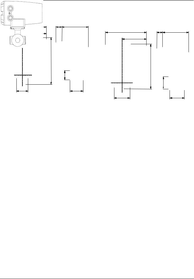
Dimensions
Unit : mm
225 |
|
(35) |
143 |
|
Unit : mm |
|
|
|
|||
|
131 |
|
225 |
(35) |
133 |
|
|
|
|
|
|
|
|
|
|
131 |
|
|
(L2) |
|
|
|
(L2) |
|
ΦD1 |
|
|
|
ΦD1 |
64 |
L1 |
|
|
87 |
L1 |
BS16, DIN PN16 and JIS 10K dimensions:
Meter size |
L1 |
L2 |
D1 |
Weight |
(mm) |
(mm) |
(mm) |
(mm) |
(kg) |
15 |
70 |
252 |
49 |
approx. 5 |
Note: 1 inch = 25.4mm
ANSI class 150 and class 300 dimensions:
Meter size |
L1 |
L2 |
D1 |
Weight |
(inch) |
(inch) |
(inch) |
(inch) |
(lb) |
1/2 |
2.76 |
9.92 |
1.93 |
approx. 11 |
BS16, DIN PN16 and JIS 10K dimensions:
Meter size |
L1 |
L2 |
D1 |
Weight |
(mm) |
(mm) |
(mm) |
(mm) |
(kg) |
25 |
80 |
241 |
66 |
approx. 5 |
Note: 1 inch = 25.4mm
ANSI class 150 and class 300 dimensions:
Meter size |
L1 |
L2 |
D1 |
Weight |
(inch) |
(inch) |
(inch) |
(inch) |
(lb) |
1 |
3.15 |
9.48 |
2.60 |
approx. 11 |
Figure 3. LF410/LF600 and LF414/LF600 flowmeters
Meter size 15mm (1/2")
Figure 4. LF410/LF600 and LF414/LF600 flowmeters
Meter size 25mm (1")
The dimension of L1 is changed when the material of grounding ring is chosen Pt-Ir or Ta.
Meter size |
|
L1 |
15mm (1/2”) |
77mm |
(3.03 inch) |
25mm (1”) |
95mm |
(3.74 inch) |
40mm (1 1/2”) |
115mm (4.53 inch) |
|
50mm (2”) |
126mm (4.96 inch) |
|
80mm (3”) |
126mm (4.96 inch) |
|
100mm (4”) |
136mm (5.35 inch) |
|
150mm (6”) |
242mm (9.53 inch) |
|
200mm (8”) |
312mm |
(12.28 inch) |
5
 Loading...