


G3 TOSVERT-130

December, 1998
ICC #10160-001
HIGH PERFORMANCE TRANSISTOR INVERTER
TRUE TORQUE CONTROL DRIVE SERIES
PROFIBUS-DP COMMUNICATIONS INTERFACE

1
Introduction
Thank you for purchasing t he “ Pr ofibus-DP Communications Interface” for the
Toshiba TOSVERT-130 G3 High-Performance Transistor Inverter. Before using t he
Profibus-DP interface, please be sur e t o t horoughly read the instructions and
precautions contained in this manual. In addition, please m ake sure that this
instruction manual is delivered to the end user of t he invert er unit into which the
Profibus-DP interface kit is installed, and keep this instruction m anual in a safe place
for future reference or inverter inspection.
This instruction manual describes the device specificat ions, wiring methods,
maintenance procedures, supported functions and usage methods for the Prof ibus-
DP communications interface.

2
Usage Precautions
•= Please use the interface only when the ambient temperature of the inverter unit into
which the interface is installed is within the following specified temperature limits:
Operation
: -10 ∼ +40°C (+14 ∼ +104°F)
Storage
: -25 ∼ +65°C (-13 ∼ +149°F)
•= Avoid installation locations that may be subjected to large shocks or vibrations.
•= Avoid installation locations that may be subjected to rapid changes in temperature or
humidity.
Operating Environment
Operating EnvironmentOperating Environment
Operating Environment
•= Do not touch charged parts such as the terminal block while the inverter’s CHARGE
lamp is lit. A charge will still be present in the inverter unit’s internal electrolytic
capacitors, and therefore touching these areas may result in an electrical shock.
Always turn all inverter input power supplies OFF, and wait at least 5 minutes after the
CHARGE lamp has gone out before connecting communication cables or motor wiring.
•= When installing the interface board into the inverter and making wiring connections,
make certain that no clippings or wiring leads that could cause device failure fall into
the inverter or onto electronic components.
•= Proper ground connections are vital for both safety and signal reliability reasons. For
proper grounding procedures, please refer to the section in this manual pertaining to
grounding (section 3).
•= Route the communication cables separate from the inverter input/output power wiring.
•= To avoid the possibility of electric shock due to leakage currents, always ground the
inverter unit’s E/GND terminal and the motor. To avoid misoperation, do not connect
the Profibus interface board's shield terminal to either of the above-mentioned grounds
or any other power ground.
Installation
Installation Installation
Installation •
••
• Wiring
Wiring Wiring
Wiring
•= The inverter’s EEPROM has a life span of 10,000 write cycles. Do not write to the
same parameter register more than 10,000 times.
•= Do not touch or insert a rod or any other item into the inverter while power is applied,
as this may lead to electrical shock or inverter damage.
•= Commission the disposal of the interface board to a specialist.
•= Do not assign the same address to more than one inverter in the same network.
•= Individual slave addresses can be set from 0 ∼ 125. Addresses 126 and above are
invalid, and will cause the inverter to trip "OPTION PCB ERROR".
•= When the inverter’s control power supply is turned on, the inverter performs
initialization functions for approximately 2 seconds, during which communications
capabilities are disabled. Communications capabilities will also be disabled for
approximately 2 seconds after momentary control power supply outages or inverter
resets.
Other Precautions
Other PrecautionsOther Precautions
Other Precautions

3
TABLE OF CONTENTS
1. Interface Board Diagram..........................................................................5
2. Interface Board Installation / Removal...................................................6
2.1 Before Installation............................................................................................6
2.2 Installation Procedure.......................................................................................7
2.3 Removal.........................................................................................................11
2.3.1 Before Removal......................................................................................11
2.3.2 Removal Procedure.................................................................................11
3. Grounding...............................................................................................14
4. Equipment Specifications .....................................................................14
5. Maintenance And Inspection.................................................................15
6. Storage And Warranty............................................................................16
6.1 Storage..........................................................................................................16
6.2 Warranty........................................................................................................16
7. G3 Parameter Settings...........................................................................17
8. Feature Summary...................................................................................18
9. Exchanged Data Structures ..................................................................20
9.1 Output (Control) Data Format.........................................................................20
9.2 Input (Status) Data Format.............................................................................22
9.3 Diagnostics.....................................................................................................24
10. Parameter Register Access................................................................25
10.1 Parameter Number / Action Output Words .................................................25
10.2 Parameter Number / Action Input Words....................................................26
10.3 Parameter Access Procedure.....................................................................27
10.4 Register Access Error Codes......................................................................28
11. Parameter Registers...........................................................................29
11.1 Read-Only Registers ..................................................................................31
11.2 Read/Write Registers .................................................................................33
11.2.1 GROUP:FUNDAMENTAL PARAMETERS #1......................................33
11.2.2 GROUP:FUNDAMENTAL PARAMETERS #2......................................34
11.2.3 GROUP:PANEL CONTROL PARAMETERS.......................................34
11.2.4 GROUP:TERMINAL SELECTION PARAMETERS ..............................35
11.2.5 GROUP:SPECIAL CONTROL PARAMETERS....................................39
11.2.6 GROUP:FREQUENCY SETTING PARAMETERS...............................40

4
11.2.7 GROUP:PROTECTION FUNCTION PARAMETERS...........................43
11.2.8 GROUP:PATTERN RUN CONTROL PARAMETERS.......................... 45
11.2.9 GROUP:FEEDBACK CONTROL PARAMETERS................................48
11.2.10 GROUP:COMMUNICATION SETTING PARAMETERS......................49
11.2.11 GROUP:AM/FM TERMINAL ADJUSTMENT PARAMS........................50
11.2.12 GROUP:UTILITY PARAMETERS........................................................51
11.2.13 GROUP:MOTOR RATING PARAMETERS ......................................... 53
11.3 Inverter Fault Codes................................................................................... 55
12. GSD File .............................................................................................. 57
13. Notes ................................................................................................... 59
5
1.
1.1.
1.
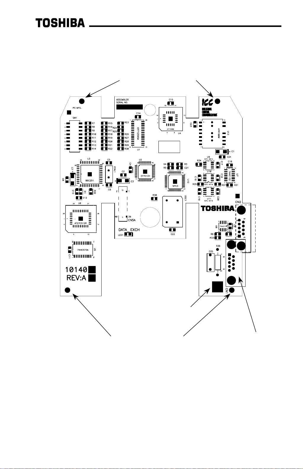
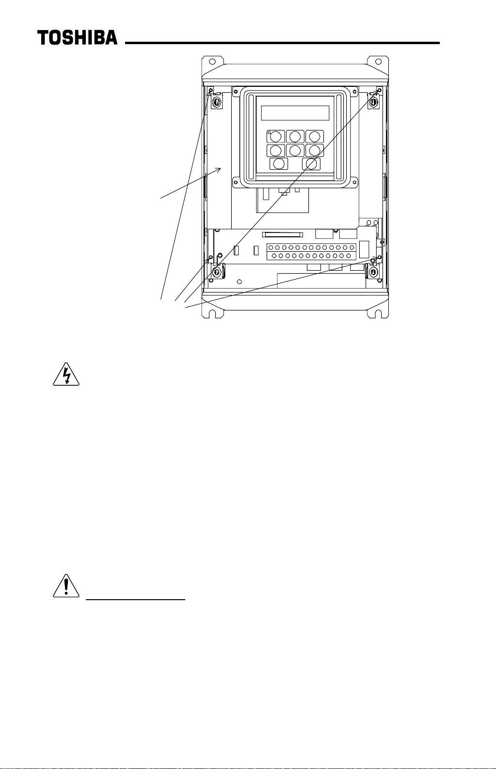
Interface Board Diagram
Interface Board DiagramInterface Board Diagram
Interface Board Diagram
Plated SHIELD connection
point for grounding (refer to
Section 3).
Standoff mounting holes
Standoff mounting holes
Network connector (CN1)

6
2.
2.2.
2.
Interface Board Installation / Removal
Interface Board Installation / RemovalInterface Board Installation / Removal
Interface Board Installation / Removal
The Profibus Communications Option ROM enclosed with the Profibus kit is
compatible only with G3 inverters with V120 or later main soft ware. An er r o r will
occur if the option ROM is installed in an inverter with pre-V120 main software. The
main software version number is printed on the CPU package (IC1) on the control
board. Additionally, this version number can be read from inverter memory by
displaying the parameter CPU VERSION in GROUP:UTILITY PARAMETERS. If you
are unsure of the software version of your inverter, please contact Toshiba
International Corporation for more information.
The Profibus option ROM version number is printed on the label attached to the
ROM. The option ROM version number can also be read from t he invert er ’s memory
and displayed on the LCD panel after initialization by displaying the parameter ROM
VERSION in GROUP:UTILITY PARAMETERS. The opt ion RO M version number
replaces the standard ROM version number after installation/initialization.
IMPORTANT NOTE: The option ROM included with the Profibus interface k it
is for installation into G3 230V/ 460V unit s only
. Do not install the option ROM into
any other inverter unit (such as H3, E3, or G 3 600V unit s ) . All inverter units other
than the G3 230V/460V series are shipped from the factory with full communications
capability, and installation of the option ROM may cause incorrect oper at ion or
inverter damage.
Please note that due to internal mechanical clearances, not all Pr ofibus connectors
can be used on all inverter units. Ensure that the Profibus connector that you plan on
using does not come into contact with any of the drive’s internal com ponents, circuit
boards or brackets. Toshiba has det er m ined t hat connectors such as the ERNI
103648 (non-terminated) and 103649 (ter m inat ed) will work for all installations. If you
have difficulty locating a connector which will work properly in your unit, please
contact Toshiba International Corpor at ion for assistance.
Additionally, certain drive models require a modified panel support bracket to allow
installation of the Prof ibus interface. Specifically, all G3 460v 10HP through 50HP
and 230v 7.5HP through 25HP units require a m odified panel support bracket. To
obtain this support bracket, contact your local distributor or Toshiba Internat ional
Corporation.
2.1
2.12.1
2.1
Before Installation
Before InstallationBefore Installation
Before Installation
All parameters will be automatically reset to the factory default values after the opt ion
ROM is installed in the inverter. If it is desir ed to retain the current parameter
settings, the user should access the user-changed parameter group to display and
record all the parameters and setting values that have been changed from factory
defaults. Even if the curr ent set tings are saved to non-volatile memory by setting the
STANDARD SETTING MODE SELECTION paramet er in GROUP:UTILITY
PARAMETERS to 5
*
, they will be erased from memory during init ialization of the option
ROM.
7
•
= Setting the standard mode selection paramet er will be referred to in this manual
as performing a TYPE X RESET, where X is the param et er setting value.
2.2
2.22.2
2.2
Installation Procedure
Installation ProcedureInstallation Procedure
Installation Procedure
Installation of the TO SHIBA Profibus option ROM and interface board into a
TOSVERT-130 G3 inverter should only be performed by a qualified technician
familiar with the maintenance and operation of the G3. To install the option RO M and
interface board, complete t he following steps:
1. Record the option ROM version number located on the label of the option ROM in
the following box. The option ROM version is the number immediately following
the “V” on the ROM label. For example, if the label indicates “V6402”, the option
ROM version is 6402. This version number will be used later in the installation
process. Option ROM version =
.
Record the standard ROM version number prior to option RO M installation. The
standard ROM version can be read from parameter ROM VERSION in
GROUP:UTILITY PARAMETERS.
Standard ROM version =
.
2. CAUTION! Verify that all input power sources to the inverter have
been turned OFF and are locked and tagged out.
3.
DANGER! Wait at least 5 minutes for the inverter’s electrolytic
capacitors to discharge before pr oceeding to step 4. Do not touch any internal
parts with power applied to the inverter, or for at least 5 minutes after
power to the inverter has been removed. A hazard exists temporarily for
electrical shock even if the source power has been removed.
4.
Remove the inverter’s cover (open the door on units with hinged doors).
Verify that the CHARGE LED has gone out before continuing the installation
process.
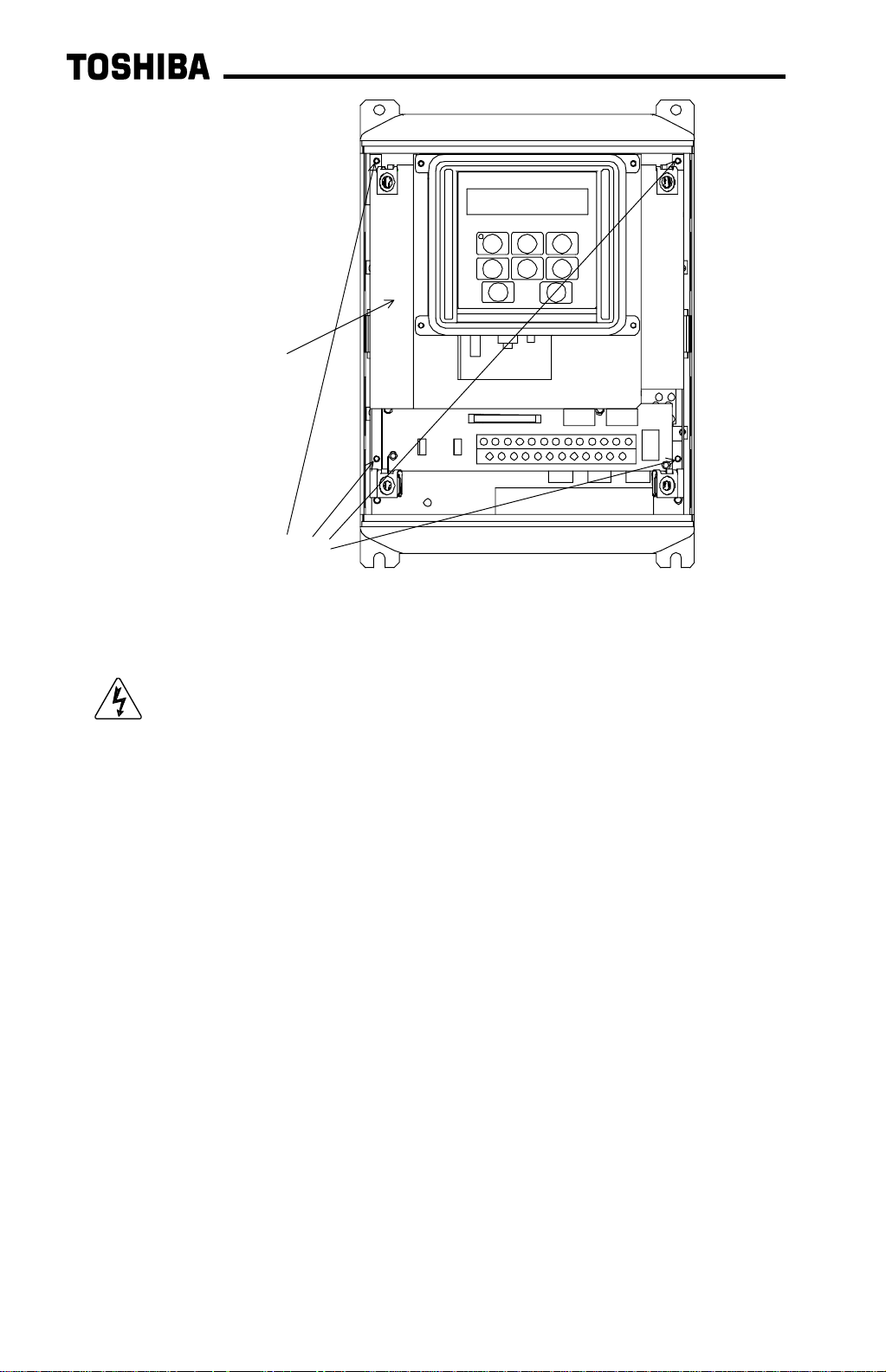
5. Loosen the 4 screws attaching the G3’s operation panel support bracket to the
control board support bracket, and t hen remove the operation panel and support
bracket as a unit (ref er to Figure 1).
8
6.
CAUTION! The option ROM PCB assembly and interface board are
static-sensitive devices. Standard electrostatic- sensit ive component handling
precautions should be observed. Locate the option ROM connector, labeled
CN41, on the lower-left side of the control PCB. Line up the connector on the
back of the option ROM PCB with CN41. Install t he opt ion ROM by pressing
gently but firmly on the option ROM PCB until a slig ht “click” is felt. Ver ify that the
option ROM PCB is seated properly and firmly in CN41. If the option ROM
connector does not appear to be mating with CN41 properly, verify that the ROM
is oriented properly and that there are no obstructions in either connector.
7. Install the 4 nylon standoffs into the holes provided in the control board support
bracket (refer to Figure 2).
operation panel support
bracket screws
operation panel
support bracket
Figure 1: G3 with front cover removed

9
8. Install the Profibus network cable through the access holes at the bot t om of the
inverter and route the cable in order to make connections to the interface board
connector (CN1). Take care to not route the cable near any sharp edges or in
positions where it may be pinched.
9. Connect the Profibus cable to the interface board connector ( CN1) . If a ground
cable is going to be used, attach the ground cable to the plated hole near CN1 on
the lower-right portion of the Profibus board (refer to section 3).
CAUTION! Extremely high voltag es exist in t he ar ea near the Profibus
interface board and connector. Ensure t hat no stray wires come into contact with
any internal inverter components. Also ensure that the com m unications cable is
not routed in such a manner that it may come int o cont act with high-voltage
inverter components, or inverter components t hat m ay heat up dur ing operation
and damage the cable insulation.
10. Install the interface board into the inverter by carefully aligning the 4 nylon
standoffs with the 4 mounting holes provided in the interface board. Ensure that
connector CN5A on the back side of the int erface board is aligned with connector
CN5 on the front side of t he cont rol board.
11. Press the interface board firmly onto the standoffs and connector CN5 until the
standoff retaining tabs lock. Ensure that CN5 and CN5A are thoroughly
interlocked.
12. Carefully re-install the operation panel and support bracket and t ighten the 4
screws that attach the operation panel support bracket to the control board
support bracket. Once installed, take a moment to verify that all int er face board
and network components have sufficient clearance from other drive components.
standoff mounting holes
Figure 2: G3 with front cover and operation panel support bracket
removed

10
13. If a ground cable is being used, connect the ground cable to t he selected ground
point.
14. Reinstall the inverter’s cover (close and latch the door on units with hinged
doors).
DANGER! Do not operate the unit with the cover off / cabinet
door open.
15. Turn all power sources to the inverter unit ON, and verify that the inverter
functions properly. If t he inverter unit does not appear to power up, or does not
function properly, immediately turn power OFF. Repeat steps 2 ∼
∼∼
∼ 4 to remove
all power from the inverter. Then, verify all connections. Cont act Toshiba
International Corporation f or assistance if the problem persists.
16. To perform final verification that t he option ROM is installed properly, display the
value of the ROM VERSION param eter in GROUP:UTILITY PARAMETERS. This
number should match the option ROM version number that was recorded in step
1. If this parameter value does not m atch the option ROM version number
recorded in step 1, repeat steps 2 ∼
∼∼
∼ 4 to remove all power from the inverter,
then re-verify that the option RO M is installed proper ly. If the option ROM
appears to be installed properly, but the version numbers st ill do not match,
contact Toshiba International Corpor at ion for further assistance.
11
2.3
2.32.3
2.3
Removal
RemovalRemoval
Removal
Removal of the Profibus inter face board from a TOSVERT-130 G3 inverter should
only be performed by a qualified technician familiar with the maintenance and
operation of the G3. In or der to protect the interface board connect or ’s r eliabilit y, do
not repeatedly connect and disconnect the interf ace. Use the following procedure if it
becomes necessary to remove the Profibus interface board from the inverter.
CAUTION! Do not remove the interface board while power is applied to
the inverter. Removing the interface board with power applied may damage the
inverter.
2.3.1
2.3.12.3.1
2.3.1
Before Removal
Before RemovalBefore Removal
Before Removal
The inverter will display an error message if t he option ROM becomes dislodged or is
removed from its socket. The inverter must be reset to clear this err or . Therefore, all
parameters will be automatically reset to the factory default values after an option
ROM has been removed from the inverter. If it is desired to retain the current
parameter settings, the user should access t he user - changed parameter group to
display and record all the parameters and setting values that have been chang ed
from factory defaults. Even if the current settings are saved using the TYPE 5
RESET function, they will be erased from memory during the re-initialization of t he
inverter after the option RO M has been removed.
2.3.2
2.3.22.3.2
2.3.2
Removal Procedure
Removal ProcedureRemoval Procedure
Removal Procedure
1. CAUTION! Verify that all input power sources to the inverter have
been turned OFF and are locked and tagged out.
2.
DANGER! Wait at least 5 minutes for the inverter’s electrolytic
capacitors to discharge before pr oceeding to step 3. Do not touch any internal
parts with power applied to the inverter, or for at least 5 minutes after
power to the inverter has been removed. A hazard exists temporarily for
electrical shock even if the source power has been removed.
3.
Remove the inverter’s cover (open the door on units with hinged doors).
Verify that the CHARGE LED has gone out before continuing the removal
process.
4. Loosen the 4 screws attaching the operation panel support bracket to the contr ol
board support bracket and remove the operat ion panel and suppor t bracket as a
unit (refer to Figure 3).
12
5. CAUTION! The option ROM PCB and Profibus interface board are
static-sensitive devices. Standard electrostatic- sensit ive component handling
precautions should be observed. Release the 4 corners of the int er face board
from the standoffs by pressing down on the standoff locking tabs with a small flat-
headed screwdriver. Be careful to not apply any abnormal stress to the int e r face
board while performing this, as t his m ay damage the interface board or control
board connectors.
6. Remove the interface board from the inverter.
7. Disconnect the communications cable from the interface board connect or (CN1),
and pull the cable out through the access holes at the bot tom of the inverter.
8. Locate the option ROM in the option ROM connector, labeled CN41, on the
lower-left side of the contr ol PCB. Gently work the option ROM PCB up and
down while pulling on it until the ROM releases from the contr ol PCB option ROM
connector.
IMPORTANT NOTE: Do not remove the option ROM on inverter units that
were received from the factory with option ROMs pre-inst alled. Units that are
shipped from the fact or y with option ROMs pre-installed (H3 and 600V G3 units,
for example) require these ROMs for correct operation, and removal of the option
ROM may cause incorrect operation or inverter damage. If you are in doubt
about the requirement of an option ROM in your inverter unit, contact Toshiba
International Corporation f or assistance.
9. Carefully re-install the operation panel and support bracket and tighten the 4
screws that attach the operation panel support bracket to the control board
support bracket.
operation panel support
bracket screws
operation panel
support bracket
Figure 3: G3 with front cover removed

13
10. Reinstall the inverter’s cover (close and latch the door on units with hinged
doors).
DANGER! Do not operate unit wit h t he cover off / cabi net
door open.
11. Turn all power sources to the inverter unit ON, and verify that the inverter
functions properly. If t he inverter unit does not appear to power up, or does not
function properly, immediately turn power O FF. Repeat st eps 1 ∼
∼∼
∼ 3 to remove
all power from the inverter. Then, verify all connections. Cont act Toshiba
International Corporation f or assistance if the problem persists.
12. To re-initialize the inverter after the ROM has been removed, perform a TYPE 3
reset. After t he init ialization sequence, display the value of the ROM VERSION
parameter in GROUP:UTILITY PARAMETERS. This number should match the
standard ROM version number that was recorded prior to option RO M installation.
If this parameter value does not match the value recorded earlier, contact
Toshiba International Corporation for further assistance.

14
3.
3.3.
3.
Grounding
GroundingGrounding
Grounding
Grounding is of particular im portance for reliable, stable operation. Communication
system characteristics may vary from system to system, depending on the system
environment and grounding method used. The Profibus interface card is pr ovided
with a plated SHIELD connection point by CN1, on the lower right-hand side of the
board. This SHIELD connection point is directly connected to the metallic housing of
the DB9 connector, which should then be connected to the shield of t he Profibus
network cable through the Profibus connector. To ground the network cable shield,
therefore, connect a wire with lug terminal t o this SHIELD point, and then connect the
other end of the wire to an appropriate g r ound. For specific details and requirements
regarding protective gr ounding and the Profibus network, refer to the Profibus
Standard (DIN 19245, part 1).
Please be sure to consider the following points f or m aking proper ground
connections:
Grounding method checkpoints
1. Make all ground connections such that no ground current flows through the
inverter case.
2. Ensure that all grounds are connected to points that are at the same pot ential as
inverter grounds.
3. Do not connect the Profibus interface board's SHIELD connection point to a
power ground or any other potential noise-producing ground connection (such as
the inverter's E/GND terminal).
4. Do not make connections to unstable grounds (paint-coated screw heads,
grounds that are subjected to induct ive noise, etc. )
4.
4.4.
4.
Equipment Specifications
Equipment SpecificationsEquipment Specifications
Equipment Specifications
Item Specification
Operating Environment
Indoors, less than 1000m above sea level, do not
expose to direct sunlight or corrosive / explosive gasses.
Operating Temperature
-10 ∼ +40°C (+14 ∼ +104°F)
Storage Temperature
-25°C ∼ +65°C (-13 ∼ +149°F)
Relative Humidity
20% ∼ 90% (without condensation)
Vibration
5.9m/s
2
{0.6G} or less (10 ∼ 55Hz)
Grounding According to DIN 19245, part 1
Cooling Method Self-cooled

15
5.
5.5.
5.
Maintenance And Inspection
Maintenance And InspectionMaintenance And Inspection
Maintenance And Inspection
Preventive maintenance and inspection is required to maint ain t he Pr ofibus
communication interface in its opt im al condition, and to ensure a long operational
lifetime. Depending on usag e and oper at ing conditions, perform a periodic
inspection once every three to six months. Before starting inspections, always turn
off all power supplies to the inverter unit , and wait at least five minutes after the
inverter’s “CHARGE” lamp has gone out .
DANGER! Do not touch any internal parts with power applied
to the inverter, or for at least 5 minutes after power to the inverter has been
removed. A hazard exists temporarily for electrical shock even if the source
power has been removed.
Inspection Points
•= Check that the network connector screws are not loose. Tighten if necessary.
•= Check that there are no def ect s in any att ached grounding wire terminal crimp
points. Visually check that the crimp points ar e not scar red by overheating.
•= Visually check the wiring and cables for damage.
•= Clean off any accumulated dust and dirt. Place special emphasis on cleaning the
ventilation ports of the inverter and all inst alled PCBs. Always keep t hese ar eas
clean, as adherence of dust and dirt can cause premature component failure.
•= If use of the inverter unit is discontinued for extended periods of time, turn the
power on at least once every two years and confirm that the unit still f unctions
properly.
•= Do not perform hi-pot t est s on t he invert er or Profibus interface board, as t hey
may damage the unit’s internal components.
Please pay close attention to all periodic inspection points and maintain a g ood
operating environment.

16
6.
6.6.
6.
Storage And Warranty
Storage And WarrantyStorage And Warranty
Storage And Warranty
6.1
6.16.1
6.1
Storage
StorageStorage
Storage
Observe the following points when the Profibus interface board is not used
immediately after purchase or when it is not used for an extended period of time.
•= Avoid storing the interface board in places t hat are hot or humid, or that contain
large quantities of dust or metallic dust. Store the interface board in a well-
ventilated location.
•= When not using the Profibus interface board for an extended period of time, turn
the power on at least once every two years and confirm that it still f unct ions
properly.
6.2
6.26.2
6.2
Warranty
WarrantyWarranty
Warranty
The Profibus communications inter face kit is covered under warranty for a period of
12 months from the date of installation, but not to exceed 18 months from the date of
shipment from the f actory. For further warranty or service inform at ion, please contact
Toshiba International Corporation.

17
7.
7.7.
7.
G3 Parameter Settings
G3 Parameter SettingsG3 Parameter Settings
G3 Parameter Settings
Profibus interface board com munications are enabled by setting parameter
COMMUNICATION SELECTION in GROUP:COMMUNICATION SETTING PARAMETERS
to 2 (Profibus, Modbus, DeviceNet). None of t he Tosline-F10 communication
parameter settings apply when using the Profibus interface. For more inf ormation on
methods for changing par ameter settings, refer t o the TOSHIBA G3 Operation
Manual.
The following is a list of the parameter settings that are req uir ed during setup to
enable Profibus communications:
Parameter Group Required Value
BLIND FUNCTION
SELECTION
GROUP:UTILITY
PARAMETERS
1
COMMUNICATIONS PARMS
BLIND
GROUP:UTILITY
PARAMETERS
1
COMMUNICATION
SELECTION
GROUP:COMMUNICATION
SETTING PARAMETERS
2
INVERTER ID NUMBER GROUP:COMMUNICATION
SETTING PARAMETERS
any value other than
126 ∼ 255.
Note:
Although the INVERTER ID NUMBER parameter can be set from 0 to 255,
the allowable Profibus slave addresses range only from 0 to 125. Therefore,
if this parameter is set t o a value from 126 to 255, the Profibus inter face card
will trip “OPTION PCB ERROR” upon initialization. To correct this error, set
the INVERTER ID NUMBER parameter to a value fr om 0 to 125.
To implement any parameter changes in GROUP:COMMUNICATION SETTING
PARAMETERS, the drive must be reset after m aking the changes.
If the drive into which a Profibus communications interface board is installed trips
“OPTION PCB ERROR” for any reason during init ialization or operation (for example,
if it becomes loose from it s m ounting connections), it is incapable of being r eset via
the Profibus network. When this trip condition occurs, t her efore, the drive can only
be reset locally via the panel or control terminal block.
If drive control (f r equency command input, RUN/STOP, etc.) is to be performed via
the Profibus network, the following inverter parameters must also be set as shown:
Parameter Group Required
Value
COMMAND MODE SELECTION GROUP:UTILITY PARAMETERS
3
FREQUENCY MODE SELECTION GROUP:UTILITY PARAMETERS
3
Of course, input data can always be monitored f r om the network regardless of the
settings of COMMAND MODE SELECTION and FREQUENCY MODE SELECTION. Also
note that if the COMMAND MODE SELECTION or FREQUENCY MODE SELECTION
parameters are changed while the drive is running, t he change will not take effect
until the next time the drive is stopped.

18
8.
8.8.
8.
Feature Summary
Feature SummaryFeature Summary
Feature Summary
The Toshiba Profibus-DP interface provides a wide array of network data access and
drive control features. Combined with the flexible configuration and high-speed data
transfer capabilities of the Profibus network, this allows powerful networked cont rol
and monitoring systems to be designed. Som e of the main features provided in the
G3 Profibus-DP interface which allow for this control and configurabilit y are briefly
described here:
Protocol
Profibus DP (Decentralized Periphery). The int er face can also co-exist
simultaneously on networks using Profibus- FMS.
Network Baud Rates
Supports all Profibus baud rates from 9.6kbaud to 12Mbaud. The network baud rate
is automatically detected and continuously monitored during operation; no parameter
settings are necessary.
Global Control Functions
•= Freeze mode
: Input (monitor) data values are held constant at the drive until the
next “freeze” command or an “unf r eeze” com m and is r eceived.
Used primarily for synchronized monitoring of multiple Profibus
nodes.
•= Sync mode
: Output (control) data values are held const ant at the drive until the
next “sync” command or an “unsync” command is received. Used
primarily for synchronized control of m u lt iple Pr ofibus nodes.
•= Clear_Data
: All output (control) dat a values are clear ed to “0”.
Address Change Functions
Set_slave_address function supported – allows modification of the drive’s INVERTER
ID NUMBER parameter . The INVERTER ID NUMBER parameter can also be
changed while in the DATA_EXCHANGE state by accessing paramet er register 204
(hex). Refer to sections 10 and 11 of this document for more infor m ation on
accessing parameter registers.
Network Watchdog
A network watchdog function is always operating within the interface – in the event of
a disconnection from the network or loss of the network master, the inter face will
automatically stop the drive for saf ety (note that either the COMMAND MODE
SELECTION or FREQUENCY MODE SELECTION parameter must be set to 3 ( net work
control) in order for the drive to stop when a watchdog time-out occurs).
 Loading...