


FILE NO : A09-01P
Quick reference
AIR TO WATER HEAT PUMP
Quick Reference Guide - Page 2
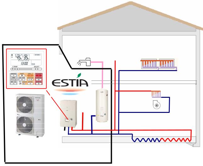
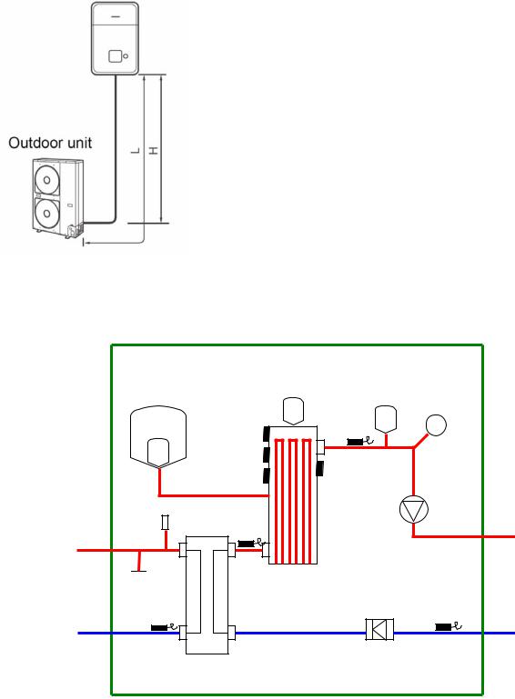
Estia System
Domestic Hot Water |
Space Conditioning |
||
|
|
|
|
Radiator
|
|
|
|
|
|
|
|
|
|
|
|
|
Fan coil unit |
||
|
|
|
|
|
|||
|
|
|
|
|
(Heating or Cooling) |
||
Outdoor unit |
|
|
Hot water |
Under floor heating |
|||
|
|
||||||
|
Hydro unit |
||||||
|
|
|
cylinder |
(Zone Control) |
|||
Estia Outdoor Unit |
|
|
|
|
|
|
|
HWS-802H-E |
8.0kW Inverter (use Hydro Unit: HWS-802XWH**-E) |
||||||
HWS-1102H-E |
11.2kW Inverter (use Hydro Unit: HWS-1402XWH**-E) |
||||||
HWS-1402H-E |
14.0kW Inverter (use Hydro Unit: HWS-1402XWH**-E) |
||||||
Estia Hydro Unit |
|
|
|
|
|
|
|
HWS-802XWHM3-E |
Plate Heat exchanger and 3kW Backup Heater |
||||||
HWS-802XWHT6-E |
Plate Heat exchanger and 6kW Backup Heater |
||||||
HWS-1402XWHM3-E |
Plate Heat exchanger and 3kW Backup Heater |
||||||
HWS-1402XWHT6-E |
Plate Heat exchanger and 6kW Backup Heater |
||||||
HWS-1402XWHT9-E |
Plate Heat exchanger and 9kW Backup Heater |
||||||
Estia Hot Water Cylinder (EU) |
|
|
|
|
|
||
HWS-1501CSHM3-E |
150L Stainless Steel Tank (with EU Accessories) |
||||||
HWS-2101CSHM3-E |
210L Stainless Steel Tank (with EU Accessories) |
||||||
HWS-3001CSHM3-E |
300L Stainless Steel Tank (with EU Accessories) |
||||||
Estia Hot Water Cylinder (UK) |
|
|
|
|
|
||
HWS-1501CSHM3-UK |
150L Stainless Steel Tank (with UK Accessories) |
||||||
HWS-2101CSHM3-UK |
210L Stainless Steel Tank (with UK Accessories) |
||||||
HWS-3001CSHM3-UK |
300L Stainless Steel Tank (with UK Accessories) |
||||||
Note:
Under floor heating, Fan Coil units, Radiators, valves and Hot Water Piping are procured locally.

Quick Reference Guide - Page 3
Notes on System Design
•The input water temperature to the Hydro Unit must be 55°C or less. Especially, be careful when there is an external heating source such as a boiler.
When hot water over 55°C returns, it may result in a failure of the unit or water leakage.
•The flow rate of the circulating water must meet the following range:-
11 and 14 kW |
17.5 L/minute or more |
8 kW |
13 L/minute or more |
If the flow rate becomes less than the minimum, the protective device is activated to stop operation. Ensure the flow rate with a bypass valve, etc. when you use a flow rate valve for the Hydro Unit.
•Do not drive water by power other than the pump built in the Hydro Unit.
•The backup heater operates supplementary to exert a prescribed capacity when the heat pump cannot exert its capacity at a low outside temperature.
•Install the Hydro Unit and water pipes in a place in which they do not freeze.
•Make the water circuit closed. Never use it as an open circuit.
•To prevent damage to the system during outdoor defrost the circulating water must be 20 litres or more. If total water amount is not enough, the unit may not function fully due to protective operation.
Options required for each function
Purpose |
Toshiba Supply |
||
Part name |
Model code |
||
|
|||
Space Heating |
- |
- |
|
|
|
|
|
Space Heating & |
|
|
|
Space Cooling |
- |
- |
|
(All Rooms) |
|
|
|
Space Heating & |
|
|
|
Space Cooling |
- |
- |
|
(partly heating only) |
|
|
|
|
|
|
|
|
150L Hot water cylinder |
HWS-1501CSHM3-E |
|
|
150L Hot water cylinder |
HWS-1501CSHM3-UK |
|
Domestic Hot Water |
210L Hot water cylinder |
HWS-2101CSHM3-E |
|
210L Hot water cylinder |
HWS-2101CSHM3-UK |
||
|
|||
|
300L Hot water cylinder |
HWS-3001CSHM3-E |
|
|
300L Hot water cylinder |
HWS-3001CSHM3-UK |
|
2-zone control |
- |
- |
|
|
|
|
|
Interlocking with |
Output control board kit |
TBC-PCIN3E |
|
boiler |
(1) |
||
|
|||
Interlocking with |
- |
- |
|
booster heater |
|||
|
|
||
Procure locally Part name
Radiator(s), Fan coil(s),
Under floor heating
Fan coil(s) only
Fan coil(s) plus
Radiator(s)
or Under floor heating Motorized 2-way valve
Motorized 3-way valve
Earth leakage breaker
Motorized mixing valve Circulator pump Buffer tank
Boiler
Electric heater
Quick Reference Guide - Page 4
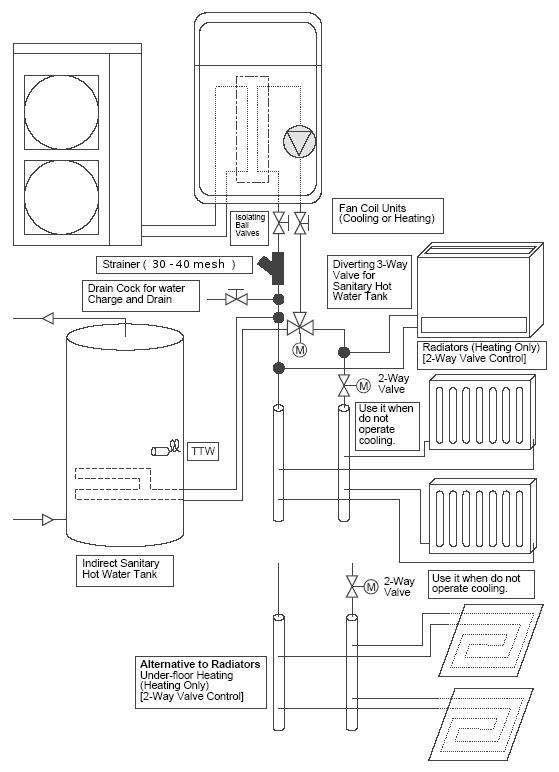
Installation Examples
Space Cooling and Space Heating with Domestic Hot Water
When both cooling and heating are used, install a 2-way valve (for cooling) to the pipe to the room for heating only.
Quick Reference Guide - Page 5
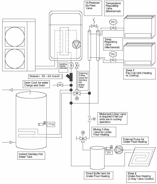
Installation Examples (cont.)
2-Zone Space Heating with Domestic Hot Water
The following shows an example of the 2-zone temperature control.
A buffer tank and a water pump are required for the 2-zone temperature control. This example is Heating only, if the Fan Coils are to be used for Cooling then a 2-Way valve must be fitted.
Quick Reference Guide - Page 6
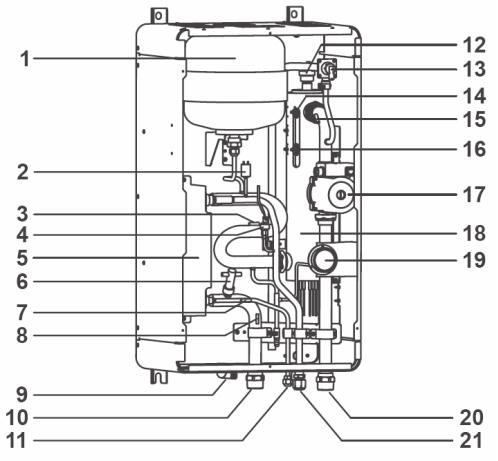
Hydro Unit – Exploded View
1 : Expansion vessel
2 : Hi pressure switch (4.15 MPa)
3 : Temperature sensor (for Heat pump outlet -TWO) 4 : Pressure sensor
5 : Heat exchanger
6 : Flow switch (13.0 L/min 17.5 L/min)
7 : Temperature sensor (for refrigerant -TC)
8 : Temperature sensor (for water inlet -TWI)
9 : Drain nipple
10 : Water inlet connection
11 : Refrigerant liquid connection
12 : Air relief valve
13 : Pressure relief valve (0.3 MPa (3 bar))
14 : Thermal protector (auto)
15 : Temperature sensor (for water outlet THO)
16 : Thermal protector (Single operation)
17 : Water pump
18 : Backup heater (3 kW, 3 kW x 2, 3 kW x 3) 19 : Manometer
20 : Water outlet connection
21 : Refrigerant gas connection
Quick Reference Guide - Page 7
Refrigerant Piping
Refrigerant Pipe Lengths and Height
The length and height of the refrigeration pipe must be within the following values.
Minimum Pipe Length
HWS-802H-E : 5 m
HWS-1102H-E : 3 m
HWS-1402H-E : 3 m
Maximum Pipe Length and Height
H: Max. ±30 m (above or below)
L: Max. 30 m
Note
The maximum pipe length cannot be increased using additional refrigerant.
Refrigeration and Water Cycle Diagrams
Hydro Unit
Refrigerant pipe at gas side (Outer ø15.88)
Refrigerant pipe at liquid side (Outer ø9.52)
|
Pressure |
|
Air vent valve |
relief |
Pressure |
valve |
||
Expansion vessel |
|
Gauge |
|
THO |
|
Sensor |
Thermal |
|
Protector |
|
Hi_P_Switch |
Pump |
TWO |
|
Sensor |
Water Out |
|
(1 1/4") |

 Backup heater P_Sensor
TWI TC Flow_Switch Sensor
Sensor
Water IN (1 1/4")
Water Heat exchanger

Quick Reference Guide - Page 8
Outdoor Unit
HWS-802H-E
HWS-1102H-E, 1402H-E
Quick Reference Guide - Page 9
Water Piping
•Install water pipes according to the regulations of respective countries.
•Install water pipes in a freeze-free place.
•Make sure that water pipes have sufficient pressure resistance (The setting value of the pressure relief valve is 0.3 MPa).
•Do not use zinc plated water pipes. When steel pipes are used, insulate both ends of the pipes.
Water Connections
•Install a strainer with 30 to 40 meshes (procure locally) at the water inlet of the Hydro Unit.
•Install drain cocks (procure locally) for water charge and discharge at the lower part of the Hydro Unit.
Water Piping Limitations
Design the water pipe length within the QH characteristics of the pump (flow-rate and pump head).
The maximum height difference for the water pipes is 7 metres.
Piping to hot water tank (option)
Water supplied to the hot water cylinder is branched by a motorized 3-way valve (procured locally).
Connect the hot water cylinder to port A (open when energized) of the valve.
Piping to 2-zone operation (option)
To perform 2-zone temperature control circulate water using another pump (procured locally) through a motorized mixing valve (procured locally) and a buffer tank (procured locally).
Quick Reference Guide - Page 10
Checking water volume and initial pressure of expansion vessel
The expansion vessel of the Hydro Unit has a capacity of 12 litres. The initial pressure of the expansion vessel is 0.1 MPa (1 bar). The suggested initial water charge is 0.2MPa (2 bar).
The pressure of the safety valve is 0.3 MPa (3 bar).
Verify whether the capacity of the expansion vessel is sufficient using the following expression. If the volume is insufficient, install an appropriate external expansion vessel.
V
< 12 L
> 12 L
Action
Internal Expansion Vessel Size OK
Internal Expansion Vessel Size too small. Install appropriate external expansion vessel
V:Necessary total vessel capacity (L)
Ɛ: |
Water expansion coefficient at average hot water temperature |
Vs: |
Total water volume in the closed system (Do not include Hot Water Cylinder) |
P1: |
System pressure at tank setting position (Mpa_abs*). |
|
(Pipe inner pressure during pump operation before heating device operates = water supply |
|
pressure) |
P2: |
Maximum pressure used during operation at tank setting position (MPa_abs*). |
|
(= safety valve setting pressure) |
* The absolute pressure value (abs.) is obtained by adding the atmospheric pressure (0.1 MPa (1 bar)) to the gauge pressure.
Water temperature and expansion coefficient (Ɛ) |
|
Water temperature and expansion coefficient (Ɛ) |
||
|
|
|
|
|
Hot water temperature |
Expansion rate |
|
Hot water temperature |
Expansion rate |
(°C) |
(Ɛ) |
|
(°C) |
(Ɛ) |
0 |
0.0002 |
|
50 |
0.0121 |
4 |
0.0000 |
|
55 |
0.0145 |
5 |
0.0000 |
|
60 |
0.0171 |
10 |
0.0003 |
|
65 |
0.0198 |
15 |
0.0008 |
|
70 |
0.0229 |
20 |
0.0017 |
|
75 |
0.0258 |
25 |
0.0029 |
|
80 |
0.0292 |
30 |
0.0043 |
|
85 |
0.0324 |
35 |
0.0050 |
|
90 |
0.0961 |
40 |
0.0078 |
|
95 |
0.0967 |
45 |
0.0100 |
|
- |
- |
Example
Maximum Hot Water temperature: 55°C, initial water charge: 0.2MPa and system volume: 200 L.
The calculated Vessel capacity (V) is 11.6 L:-
11.6 |
= |
0.0145 |
x |
200 |
|
1 |
- |
(0.2+0.1) |
|||
|
|
||||
|
|
(0.3+0.1) |
|||
|
|
|
|
In this case V < 12 L therefore the internal expansion vessel is sufficient.
There is no need to install an external expansion vessel.
 Loading...