


 Loading...
Toshiba Personal Computer
Equium A60/Satellite A60
/ Pro A60 / A65
Maintenance Manual
TOSHIBA CORPORATION
S/ No.
Equium A60/Satellite A60/ Pro A60/A65 Maintenance Manual

Copyright
© 2004 by Toshiba Corporation. All rights reserved. Under the copyright laws, this manual cannot be reproduced in any form without the prior written permission of Toshiba. No patent liability is assumed with respect to the use of the information contained herein.
Toshiba Equium A60/Satellite A60/ Pro A60/A65 Maintenance Manual
Second edition Aug 2004
Disclaimer
The information presented in this manual has been reviewed and validated for accuracy. The included set of instructions and descriptions are accurate for the Equium A60/Satellite A60/ Pro A60/A65 at the time of this manual's production. However, succeeding computers and manuals are subject to change without notice. Therefore, Toshiba assumes no liability for damages incurred directly or indirectly from errors, omissions, or discrepancies between any succeeding product and this manual.
Trademarks
Intel and Pentium are registered trademarks of Intel Corporation.
IBM, IBM PC/XT, PC/AT, PS/2 and OS/2 are registered trademarks of IBM Corporation. MS-DOS and Windows XP home edition are registered trademarks of Microsoft Corporation. Sound Blaster and Pro are trademarks of Creative Technology Ltd.
UNIX is a registered trademark of X/Open Company Ltd. NetWare are registered trademarks of Novell, Inc.
All other properties are trademarks or registered trademarks of their respective holders.
ii |
Equium A60/Satellite A60/ Pro A60/A65 Maintenance |
Manual |
|
Preface
This maintenance manual describes how to perform hardware service maintenance for the Toshiba Personal Computer Equium A60/Satellite A60/ Pro A60/A65, referred to as Equium A60/Satellite A60/ Pro A60/A65 in this manual.
The procedures described in this manual are intended to help service technicians isolate faulty Field Replaceable Units (FRUs) and replace them in the field.
SAFETY PRECAUTIONS
Four types of messages are used in this manual to bring important information to your attention. Each of these messages will be italicized and identified as shown below.
DANGER: “Danger” indicates the existence of a hazard that could result in death or serious bodily injury, if the safety instruction is not observed.
WARNING: “Warning” indicates the existence of a hazard that could result in bodily injury, if the safety instruction is not observed.
CAUTION: “Caution” indicates the existence of a hazard that could result in property damage, if the safety instruction is not observed.
NOTE: “Note” contains general information that relates to your safe maintenance service.
Improper repair of the computer may result in safety hazards. Toshiba requires service technicians and authorized dealers or service providers to ensure the following safety precautions are adhered to strictly.
?Be sure to fasten screws securely with the right screwdriver. If a screw is not fully fastened, it could come loose, creating a danger of a short circuit, which could cause overheating, smoke or fire.
?If you replace the battery pack, RTC battery or backup battery, be sure to use only the same model battery or an equivalent battery recommended by Toshiba. Installation of the wrong battery can cause the battery to explode.
Equium A60/Satellite A60/ Pro A60/A65 Maintenance Manual |
iii |

The manual is divided into the following parts:
Chapter 1 Hardware Overview describes the Equium A60/Satellite A60/ Pro A60/A65 system unit and each FRU.
Chapter 2 Troubleshooting Procedures explains how to diagnose and resolve FRU problems.
Chapter 3 Test and Diagnostics describes how to perform test and diagnostic operations for maintenance service.
Chapter 4 Replacement Procedures describes the removal and replacement of the FRUs.
Appendices |
The appendices describe the following: |
?Handling the LCD module
?Board layout
?Keyboard scan/character codes
?Key layout
?Wiring diagrams
?BIOS Rewrite Procedures
iv |
Equium A60/Satellite A60/ Pro A60/A65 Maintenance |
Manual |
|

Conventions
This manual uses the following formats to describe, identify, and highlight terms and operating procedures.
Acronyms
On the first appearance and whenever necessary for clarification acronyms are enclosed in parentheses following their definition. For example:
Read Only Memory (ROM)
Keys
Keys are used in the text to describe many operations. The key top symbol as it appears on the keyboard is printed in boldface type.
Key operation
Some operations require you to simultaneously use two or more keys. We identify such operations by the key top symbols separated by a plus (+) sign. For example, Ctrl + Pause (Break) means you must hold down Ctrl and at the same time press Pause (Break). If three keys are used, hold down the first two and at the same time press the third.
User input
Text that you are instructed to type in is shown in the boldface type below:
DISKCOPY A: B:
The display
Text generated by the XXXXX that appears on its display is presented in the type face below:
Format complete
System transferred
Equium A60/Satellite A60/ Pro A60/A65 Maintenance Manual |
v |

Table of Contents
Chapter 1 |
Hardware Overview |
|
|
1.1 |
Features |
................................................................................................................... |
1-1 |
1.2 |
System Unit ..........................................................................................Components |
1-8 |
|
1.3 |
2.5-inch ........................................................................................................HDD |
1-14 |
|
1.4 |
DVD-ROM ..................................................................................................Drive |
1-15 |
|
1.5 |
CD-RW/DVD ....................................................................................-ROM Drive |
1-16 |
|
1.6 |
DVD Multi............................................................................................................. |
1-17 |
|
1.7DVD-R/-RW…………………………………………………………………….1-18
1.8DVD Dual……………………………………………………………………….1-19
1.9DVD Super Multi……………………………………………………………….1-20
2.0 |
Power Supply......................................................................................................... |
1-21 |
|
2.1 |
Batteries |
................................................................................................................. |
1-22 |
|
1.1.1 ........................................................................................ |
Main Battery |
1-22 |
|
1.1.2 ...................................................................... |
Battery Charging Control |
1-22 |
|
1.1.3 ......................................................................................... |
RTC Battery |
1-23 |
Chapter 2 |
Troubleshooting |
|
|
2.1 |
Outline ..................................................................................................................... |
|
2-1 |
2.2 |
Basic Flowchart........................................................................................................ |
2-2 |
|
2.3 |
Power Supply........................................................................................................... |
2-6 |
|
|
Procedure ............................................................................1 Power Icon Check |
2-6 |
|
|
Procedure .............................................................................2 Connection Check |
2-8 |
|
|
Procedure ..........................................................................3 Replacement Check |
2-8 |
|
2.4 |
System Board........................................................................................................... |
2-9 |
|
|
Procedure ......................................................................3 Replacement Check |
2-10 |
|
2.5 |
2.5-inch ........................................................................................................HDD |
2-11 |
|
vi |
Equium A60/Satellite A60/ Pro A60/A65 Maintenance |
Manual |
|

|
Procedure 1 Message Check .............................................................................. |
2-11 |
|
|
Procedure 2 |
Partition Check............................................................................ |
2-11 |
|
Procedure 3 |
Format Check .............................................................................. |
2-12 |
|
Procedure 4 Test Program Check..................................................................... |
2-13 |
|
|
Procedure 5 Connector Check and Replacement Check ................................... |
2-14 |
|
2.6 |
Keyboard............................................................................................................... |
|
2-15 |
|
Procedure 1 Test Program Check ........................................................................ |
2-15 |
|
|
Procedure 2 Connector Check and Replacement Check....................................... |
2-15 |
|
2.7 |
Display................................................................................................................... |
|
2-16 |
|
Procedure 1 External Monitor Check................................................................ |
2-16 |
|
|
Procedure 2 Test Program Check..................................................................... |
2-16 |
|
|
Procedure 3 Connector Check and Replacement Check ................................... |
2-16 |
|
2.8 |
ODD (Optical Disk Drive)...................................................................................... |
2-18 |
|
|
Procedure 1 ODD Cleaning Check................................................................... |
2-18 |
|
|
Procedure 2 Test Program Check..................................................................... |
2-18 |
|
|
Procedure 3 Connector Check and Replacement Check ................................... |
2-18 |
|
2.9 |
LAN ...................................................................................................................... |
|
2-20 |
|
Procedure 1 Test Program Check..................................................................... |
2-20 |
|
|
Procedure 2 Connector Check and Replacement Check ................................... |
2-20 |
|
2.10 |
SD Card/Memory Stick(Optional) .......................................................................... |
2-21 |
|
|
Procedure 1 Test Program Check..................................................................... |
2-21 |
|
|
Procedure 2 |
Connector Check ......................................................................... |
2-21 |
2.11 |
Parallel Port(Optional) ............................................................................................ |
2-22 |
|
|
Procedure 1 Test Program Check..................................................................... |
2-22 |
|
|
Procedure 2 |
Connector Check ......................................................................... |
2-22 |
2.12 |
Audio Test ............................................................................................................. |
|
2-23 |
|
Procedure 1 Test Program Check ........................................................................ |
2-23 |
|
|
Procedure 2 Connector Check and Replacement Check....................................... |
2-23 |
|
2.13 |
IEEE 1394 Test(Optional) ...................................................................................... |
2-24 |
|
|
Procedure 1 Test Program Check..................................................................... |
2-24 |
|
Equium A60/Satellite A60/ Pro A60/A65 Maintenance Manual |
vii |

|
Procedure 2 Connector Check ......................................................................... |
2-24 |
|
2.14 |
Cooling Module...................................................................................................... |
2-25 |
|
|
Procedure 1 Test Program Check..................................................................... |
2-25 |
|
|
Procedure 2 Connector Check and Replacement Check ................................... |
2-25 |
|
Chapter 3 |
Diagnostic Programs |
|
|
3.1 |
General .................................................................................................................... |
|
3-1 |
3.2 |
Quick Start............................................................................................................... |
3-3 |
|
3.3 |
Option...................................................................................................................... |
|
3-9 |
3.4 |
Subtests ................................................................................................................. |
|
3-18 |
3.5 |
System Test............................................................................................................ |
3-22 |
|
3.6 |
Memory Test.......................................................................................................... |
3-29 |
|
3.7 |
Storage .................................................................................................................. |
|
3-34 |
3.8 |
Video..................................................................................................................... |
|
3-39 |
3.9 |
Audio..................................................................................................................... |
|
3-58 |
3.10 |
Mode Error Codes and description......................................................................... |
3-59 |
|
viii |
Equium A60/Satellite A60/ Pro A60/A65 Maintenance |
Manual |
|

Chapter 4 |
Replacement Procedures |
|
|
4.1 |
General .................................................................................................................... |
|
4-1 |
4.2 |
Wireless Lan Card.................................................................................................. |
4-18 |
|
4.3 |
HDD...................................................................................................................... |
|
4-20 |
4.4 |
Switch Cover and Hotkey Board ............................................................................ |
4-23 |
|
4.5 |
Keyboard............................................................................................................... |
4-25 |
|
4.6 |
ODD Bay Module .................................................................................................. |
4-27 |
|
4.7 |
Display Assembly................................................................................................... |
4-30 |
|
4.8 |
Top Cover ............................................................................................................. |
4-32 |
|
4.9 |
Speakers |
................................................................................................................ |
4-35 |
4.10 |
Cooling Module...................................................................................................... |
4-37 |
|
4.11 |
CPU ...................................................................................................................... |
|
4-40 |
4.12 |
System Board......................................................................................................... |
4-43 |
|
4.13 |
North Bridge Cooling Module and MDC cable ....................................................... |
4-45 |
|
4.14 |
Display Mask ......................................................................................................... |
4-47 |
|
4.15 |
FL Inverter Board .................................................................................................. |
4-49 |
|
4.16LCD Module…………………………………………………………………….4-51
4.17LED Board………………………………………………………………………4-57
4.18Touch Pad……………………………………………………………………….4-59
Equium A60/Satellite A60/ Pro A60/A65 Maintenance Manual |
ix |

Appendices |
|
|
Appendix A |
Handling the LCD Module .............................................................................. |
A-1 |
Appendix B |
Board Layout................................................................................................... |
B-1 |
Appendix C |
Keyboard Scan/Character Codes.................................................................... |
C-1 |
Appendix D |
Key Layout..................................................................................................... |
D-1 |
Appendix E |
Wiring Diagrams .............................................................................................. |
E-1 |
Appendix F |
BIOS Rewrite Procedures................................................................................ |
F-1 |
Appendix G |
EC/KBC Rewrite Procedures ......................................................................... |
G-1 |
x |
Equium A60/Satellite A60/ Pro A60/A65 Maintenance |
Manual |
|
Chapter 1
Hardware Overview

1 Hardware Overview
1-ii |
Equium A60/Satellite A60/ Pro A60/A65 Maintenance Manual |

1 Hardware Overview
Chapter 1 |
Contents |
|
1.1 Features............................................................................................................................. |
|
1-1 |
1.2 System Unit Components ................................................................................................... |
1-8 |
|
1.3 2.5-inch HDD.................................................................................................................. |
|
1-14 |
1.4 DVD-ROM Drive............................................................................................................ |
1-15 |
|
1.5 CD-RW/DVD-ROM Drive ............................................................................................. |
1-16 |
|
1.6 DVD Multi....................................................................................................................... |
|
1-17 |
1.7 DVD-R/-RW................................................................................................................... |
|
1-18 |
1.8 DVD Dual ....................................................................................................................... |
|
1-19 |
1.9 DVD Super Multi............................................................................................................. |
|
1-20 |
2.0 Power Supply .................................................................................................................. |
|
1-21 |
2.1 Batteries .......................................................................................................................... |
|
1-22 |
1.1.1 |
Main Battery ........................................................................................ |
1-22 |
1.1.2 |
Battery Charging Control...................................................................... |
1-22 |
1.1.3 |
RTC Battery......................................................................................... |
1-23 |
Equium A60/Satellite A60/ Pro A60/A65 Maintenance Manual |
1-iii |

1 Hardware Overview
Figures |
|
|
Figure 1- 1 Parts description placement ................................................................................... |
1-5 |
|
Figure 1- 2 The computer Block diagram ................................................................................ |
1-6 |
|
Figure 1- 3 |
System Board configuration.................................................................................. |
1-7 |
Figure 1- 4 System unit block diagram..................................................................................... |
1-8 |
|
Figure 1- 5 |
2.5-inch HDD..................................................................................................... |
1-14 |
Figure 1- 6 |
DVD-ROM drive ............................................................................................... |
1-15 |
Tables |
|
|
Table 1- 1 2.5-inch HDD specifications................................................................................. |
1-14 |
|
Table 1- 2 DVD-ROM drive specifications ........................................................................... |
1-15 |
|
Table 1- 3 CD-RW/DVD-ROM drive specifications .............................................................. |
1-16 |
|
Table 1- 4 DVD-Multi drive specifications ............................................................................. |
1-17 |
|
Table 1- 5 DVD-R/-RW drive specifications.......................................................................... |
1-18 |
|
Table 1- 6 DVD-Dual drive specifications ............................................................................. |
1-19 |
|
Table 1- 7 DVD Super Multi drive specifications.................................................................... |
1-20 |
|
Table 1- 8 |
Battery specifications ........................................................................................... |
1-22 |
Table 1- 9 |
Quick/normal charging time .................................................................................. |
1-22 |
1-iv |
Equium A60/Satellite A60/ Pro A60/A65 Maintenance Manual |

1.1 Features |
1 Hardware Overview |
1.1 Features
The Toshiba Equium A60/Satellite A60/ Pro A60/A65 is a full size notebook PC based on the Intel Portability Mobile Pentium 4 processor, providing high-speed processing capabilities and advanced features. The computer employs a Lithium Ion battery that allows it to be battery-operated for a longer period of time. The display uses 14.1-inch XGA and 15-inch XGA LCD panel, capable of displaying up to 26M colors at a resolution of 1024 by 768 pixels (XGA) and 1280 by 1024 pixels(SXGA+), The (PGA socket supports BTO/CTO for the CPU so that the system can be designed to suit your needs.
The computer has the following features.
? Processor
The CPU is the Intel Mobile Pentium 4 (Northwood), Mobile Pentium 4 (Prescott) and Celeron(Northwood), Celeron-D(Prescott).
Mobile Pentium 4(Northwood) 2.8/3.06/3.2 GHz
Mobile Pentium 4(Prescott) 518(2.8G)/532(3.06G)/538(3.2G)/552(3.46G)
/558(3.60G) GHz
Celeron(Northwood) 2.5/2.6/2.7/2.8 GHz
Celeron-D(Prescott) 325(2.53G)/330(2.66G)/335(2.8G)/340(2.93G)/345(3.06G)
350(3.2G) GHz
? Host bridge system controller
System controller: ATi RC300ML
? Memory
The computer has on Board 256MB/512MB memory and one SO DIMMs slot comes standard with DDR 2700 module. It supports PC2700 and uses SO DIMMs (DDR SDRAM) driven at 2.5 V, accepting BTO/CTO for your memory requirements. It can incorporate up to 1.5 GB of main memory
using the following sizes of memory modules:
?256 MB (16M? 16? 8P)
?512 MB (32M? 16? 8P)
?1024 MB (64Mx16x8P)
Equium A60/Satellite A60/ Pro A60/A65 Maintenance Manual |
1-1 |

1 Hardware Overview |
1.1 Features |
?Hard Disk Drive (HDD)
The compu ter accommodates one 2.5-inch HDD with any of the following storage capacities:
?30 GB (9.5 mm thick) ATA100 (4,200rpm)
?40 GB (9.5 mm thick) ATA100 (4,200rpm)
?60 GB (9.5 mm thick) ATA100 (4,200rpm)
?80 GB (9.5 mm thick) ATA100 (4,200rpm)
?40 GB (9.5 mm thick) ATA100 (5,400rpm)
?60 GB (9.5 mm thick) ATA100 (5,400rpm)
?80 GB (9.5 mm thick) ATA100 (5,400rpm)
?ODD
The ODD can accommodate a CD-ROM, DVD-ROM, DVD-R/RW, DVD+-R/+-RW,DVD super Multi drives.
?Display
The LCD displays available come in the following three sizes:
14.1” XGA-TFT/15” XGA-TFT/15” XGA-CSV+-TFT color display, resolution 1024? 768, 16M/1280? 1024,262,144 colors with dithering.
?Keyboard
The keyboard has 27 kinds countries key.
?Batteries
The computer has a removable 8 Cell or 12 Cell Lithium Ion battery pack and an internal RTC battery (rechargeable).
?Universal Serial Bus (USB) ports
The computer has three USB 1.1/2.0 ports, It is supported to daisy-chain a maximum of 127 USB devices. The serial data transfer rate is 480 Mbps or 12 Mbps and 1.5 Mbps These ports support PnP installation and hot plugging.
?External monitor port
A 15-pin external monitor port is provided, through which the computer automatically recognizes an external VESA DDC 2B compatible monitor.
?PC Card slot
A PC Card slot is provided to hold PC Card Standard Type II (5.0 mm) card, capable of using a variety of PC Cards including 16-bit Multiple Function PC Cards and CardBus cards.
PC card HDD boot does Not be supported.
1-2 |
Equium A60/Satellite A60/ Pro A60/A65 Maintenance Manual |

1.1 Features |
1 Hardware Overview |
?SD/MS/MMC Card
This slot is BTO/CTO for your memory card requirements to provide memory card read on your computer
?Toshiba Pointing Device
Toshiba Pointing Device has one kind of input devices TouchPad.
Equium A60/Satellite A60/ Pro A60/A65 Maintenance Manual |
1-3 |

1 Hardware Overview |
1.1 Features |
?Sound system
The ALC250 integrated audio controller supports multimedia. The sound system contains the following:
?Stereo speakers
?Headphone jack
?External microphone jack
?LAN
The internal LAN board supports 10BASE-T and 100BASE-TX, enabling connection to a LAN at up to 100 Mbps. It also supports Wake-up On LAN From S3 PXE boot support. The LAN board has the RJ45 jack to directly accommodate a LAN cable.
?Wireless LAN
The internal Mini PCI Card slot supports IEEE802.11a/g(11ch)/ IEEE802.11g(11ch)/ IEEE802.11a/g(13ch)/ IEEE802.11g(13ch) card. The Antenna is integrated in the system unit.
?Internal Modem
The computer contains a MDC, enabling data and fax communication. It supports ITUTV.90/V.92(America, Canada) The transfer rates are 56 Kbps for data reception, 33.6 Kbps for data transmission, and 14,400 bps for fax transmission. Note, however, that the actual speed depends on the line quality. The RJ11 modem jack is used to accommodate a telephone line.
?IEEE 1394(optional)
The IEEE 1394 is optional integrated device. to supported IEEE 1394 ports ,The serial data transfer rate is 400 Mbps, These port support hot plugging.
?Parallel Port(optional)
The Parallel Port is optional integrated device. to supported connect a printer or another parallel device. The port is IEEE-1284 compliant and supports Extended Capabilities Port (ECP).
?CD Key
The CD Key supports to play Audio CD directly
?Fast Serial InfraRed (FIR) communications port(optional)
The FIR Port is optional integrated device. It provided an IrDA 1.1 compatible FIR port , enabling wireless communication at a high speed of 1.15 or 4 Mbps.
1-4 |
Equium A60/Satellite A60/ Pro A60/A65 Maintenance Manual |

1.1 Features |
1 Hardware Overview |
? Figures 1-1 and 1-2 show the computer and its system unit configuration, respectively.
Equium A60/Satellite A60/ Pro A60/A65 Maintenance Manual |
1-5 |
1.1 Features |
1 Hardware Overview |
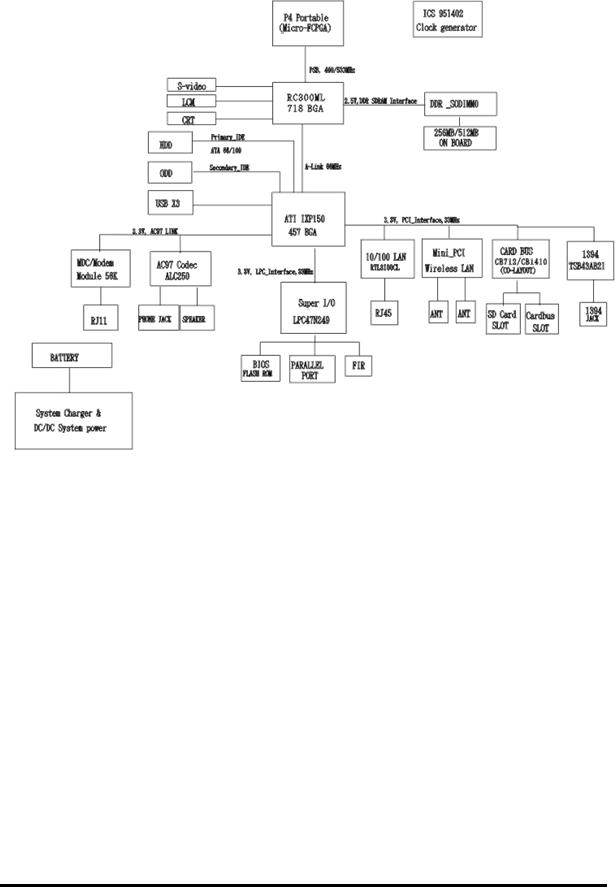
Figure 1- 2 The computer Block diagram
Equium A60/Satellite A60/ Pro A60/A65 Maintenance Manual |
1-6 |
1.1 Features |
1 Hardware Overview |
|
|
|
|
|
|
|
|
|
|
|
|
|
|
|
|
|
|
CRT |
|
|
|
|
|
|
|
|
|
|
|
|
|
|
|
|
|
|
|
|
|
||||
|
|
|
|
|
|
|
|
|
|
|
|
|
|
|
|
|
|
|
|
|
|
|
Speaker |
|
|
|
|
|
|
|
|
|
|
||||||||||
|
|
|
|
|
|
|
|
|
|
|
|
|
|
|
|
|
|
|
|
|
|
|
|
|
|
|
|
|
|
|
|
|
|
|
|
||||||||
|
|
|
|
|
|
|
|
|
|
|
|
|
|
|
|
|
|
|
|
|
|
|
|
|
|
|
|
Left |
|
|
|
|
|
|
|
|
|||||||
|
|
|
|
|
|
|
|
|
|
|
|
|
|
|
|
|
|
|
|
|
|
|
|
|
|
|
|
|
|
|
|
|
|
|
|
|
|
|
|
|
|
||
|
|
|
|
|
|
Expansion |
|
|
|
|
|
|
|
|
|
|
|
|
|
|
|
|
|
|
|
|
|
|
|
|
|
|
|
|
|
|
|
|
|||||
CPU |
|
|
|
|
Memory |
|
|
SD/MS |
|
|
|
|
|
PC Card |
|
|
|
|
|
Speaker |
|
Head |
|
||||||||||||||||||||
|
|
|
|
|
|
|
|
|
|
|
|
|
|
|
|
|
|
|
Phone |
|
|||||||||||||||||||||||
|
|
|
|
|
|
|
|
|
|
|
|
|
|
Card |
|
|
|
|
|
Slot |
|
|
|
|
|
Right |
|
|
|||||||||||||||
|
|
|
|
|
|
|
|
|
|
|
|
|
|
|
|
|
|
|
|
|
|
|
|
|
|
|
|
|
|
|
|
|
|
||||||||||
|
|
|
|
|
|
|
|
|
|
|
|
|
|
|
|
|
|
|
|
|
|
|
|
|
|
|
|
|
|
|
|
|
|
|
|
|
|
|
|
|
|
|
|
|
|
|
|
|
|
|
|
|
|
|
|
|
|
|
|
|
|
|
|
|
|
|
|
|
|
|
|
|
|
|
|
|
|
|
|
|
|
|
|
|
|
|
|
Cooling
Module
AC Adapter
System Board
MINI PCI
RJ-45
RJ-11
|
|
|
|
|
|
|
|
|
|
|
|
|
|
|
|
|
|
|
|
|
|
|
|
|
|
|
|
|
|
|
|
|
|
|
|
|
|
|
|
|
|
|
|
|
|
|
|
|
|
|
|
|
|
|
|
|
|
|
|
|
|
|
|
|
|
|
|
|
|
|
|
|
|
|
|
|
|
|
|
|
|
|
|
LAN |
|
|
Main |
|
||||
|
|
ODD |
|
|
|
|
|
|
|
LPT |
|
|
|
|
|
|
|
|
|
|
|
|
Battery |
|
||||||
|
|
|
|
|
|
|
|
|
|
|
|
|
|
|
|
|
|
|
|
|
|
|
|
|
|
|
|
|||
|
|
|
|
|
|
|
|
|
|
|
|
|
|
|
|
|
|
|
|
|
|
|
|
|
|
|
|
|
|
|
|
|
|
|
|
|
|
|
|
|
|
|
|
|
|
|
|
|
|
|
|
|
|
|
|
|
|
|
|
|
|
|
|
|
|
|
|
INT |
|
|
|
|
|
|
Wireless |
|
|
|
|
|
|
|
|
|
|
|||||||
|
|
|
|
|
|
HDD |
|
|
|
|
|
|
Lan |
|
|
|
|
|
|
|
|
|
|
|||||||
|
|
|
|
|
|
|
|
|
|
|
|
|
|
|
|
|
|
|
|
|
|
|
|
|
|
|||||
|
|
|
|
|
|
|
|
|
|
|
|
|
|
|
|
|
|
|
|
|
|
|
|
|
|
|
|
|
|
|
Ext.
MIC
LCD/FL
Inverter
IEEE 1394
Touch PAD
Keyboard
RTC
Battery
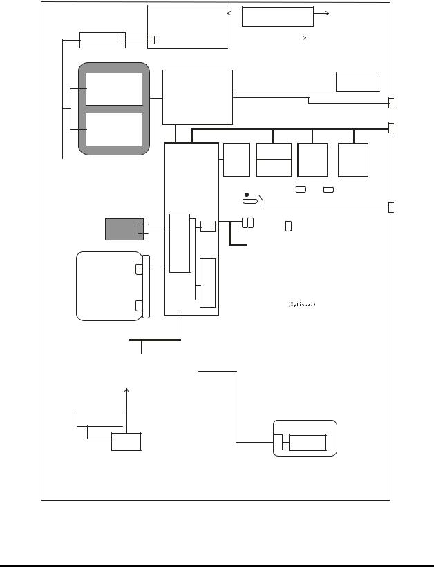
Figure 1- 3 System Board configuration
Equium A60/Satellite A60/ Pro A60/A65 Maintenance Manual |
1-7 |
1.2 System Unit Components |
1 Hardware Overview |
1.2 System Unit Components
Figure 1-4 is a block diagram of the system unit.
A D M 1032
(T h erm al Se nsor)
P C 270 0 D R A M 3 33 M H z
O n Bo ard M em o ry 25 6/5 12
CPU : Intel M ob ile
P 4 or Ce lero n
2 .5..,3.7 3 G H z M icro FC .P G A 2 m P G A 47 8
ATI RC300ML
N orth Bridge
M ain C L K G en era l. (IC S 9 51 40 2)
C P U V ID |
L M |
27 29 |
D C |
|
|
|
|
|
|
|
|
L C D 14 " or
 ”
”
L V D S
C R T
E xp an sion M em o ry
25 6/5 12 /1 02 4
A _ L ink
|
|
|
|
|
S M |
|
L A N |
|
B us |
|
|
|
C on t. |
|
C on t. |
|
|
|
R T L 81 00 C L |
S outh Bridge |
|
|
|
|
E E P R O M |
|
|
||
IX P 150 |
|
|
||
|
|
R J4 5 |
||
|
|
|
||
|
|
|
|
|
Interna l PC I Bus |
|
|
|
||||
|
M in i |
|
|
|
|
|
|
|
|
|||
|
P C I Slo t |
|
|
C ardb us |
1 39 4 |
|||||||
|
|
|
|
|
|
|
||||||
|
|
|
|
|
|
|
C on troller |
T S B 4 3A B 21 |
||||
80 2.1 1b g/ |
|
|
CB712 |
|
|
|
||||||
C o m b o |
|
|
CB1410 |
|
|
|
||||||
(W ireless |
LA N ) |
|
|
|
||||||||
|
|
|
|
|
|
|
|
|
|
|
|
|
|
|
|
|
|
|
|
|
|
|
|
|
|
|
|
|
|
|
|
|
|
|
|
|
|
|
|
|
|
|
|
|
|
|
|
|
|
13 94 |
|
|
A ntena PC M C IA SD /M S |
|||||||||||
|
|
C N N x 1 |
||||||||||
In t-H D D 30 -8 0G B 9.5 m m
ID E
C on t.
|
|
|
C D |
-R O M |
|
|
|
|||
|
|
|
D V D |
-R O M |
|
|
|
|||
|
|
|
D V D |
+ R W |
|
|
|
|||
|
|
|
D V D |
S up er M ulti |
|
|
|
|
||
|
|
|
|
|
|
|
|
P C I-P C |
|
|
|
|
|
|
|
|
|
|
|
|
|
|
|
|
|
|
|
|
|
B rid g e |
|
|
|
|
|
|
|
|
|
|
|
|
|
|
|
|
|
|
|
|
In ternal LP C |
|
|
|
|
|
|
|
|
|
|
|
|||
|
|
|
|
|
E C /K B C |
|
|
|||
F la sh |
|
|
|
|
|
|||||
R O M |
|
|
|
(L PC 47N 249) |
|
|
||||
|
|
|
||||||||
|
|
|
|
|
|
|
|
|
|
|
|
|
|
|
|
|
|
|
|
|
|
|
|
|
|
|
|
|
|
|
|
|
S tick Point K/B
K P A A C 12 6 9A
A C 9 7
U S B C on t. (02 )
A C |
M D C |
|
|
|
|
|
|
|
|
|
|
|
M o dem |
|
|
|
R J11 |
|
|||||
|
|
|
|
|
|||||||
|
|
|
|
|
|
|
|
|
M ic |
|
|
|
|
|
|
|
|
|
|
||||
|
|
|
|||||||||
|
|
|
|
|
|
|
|
|
|
|
|
|
|
|
|
|
|
|
|
|
|
|
|
|
C O D E C |
|
|
|
|
|
S pe akerx2 |
|
|||
|
A L C 2 50 |
|
|
|
|
A M P |
|
|
|
|
|
|
|
|
|
|
|
|
|
|
|
|
|
|
|
|
|
|
|
M ax 97 50 A T E I |
|
|
|
H P |
|
|
|
|
|
|
|||||||
|
|
|
|
|
|
|
|
|
|
|
|
U S B P 0 |
|
|
|
|
|
|
|
|
|
U S B |
|
|
|
|
|
|
|
|
|
|
|
||
U S B P 1 |
|
|
|
|
|
|
|
|
|
U S B |
|
|
|
|
|
|
|
|
|
|
|
||
|
|
|
|
|
|
|
|
|
|
||
U S B P 2 |
|
|
|
|
|
|
|
|
|
U S B |
|
|
|
|
|
|
|
|
|
|
|
||
|
|
|
|
|
|
|
|
|
|
|
|
M ain Battery
I2C
E 2P R O M
Figure 1- 4 System unit block diagram
Equium A60/Satellite A60/ Pro A60/A65 Maintenance Manual |
1-8 |

1.2 System Unit Components |
1 Hardware Overview |
The system unit of the computer consists of the following components:
?Processor: Intel Portability Mobile Pentium 4 and Celeron
?Mobile Pentium 4 (Prescott)
?Core speed: 2.8,3.06,3.2,3.46,3.6 GHz
?System bus: 533 MHz
?On-die level 2 cache 1 MB
?Advanced Power Management features including Enhanced Intel ® SpeedStep ® technology
?Mobile Pentium 4 (Northwood)
?Core speed: 2.8,3.06,3.2 GHz
?System bus: 533 MHz
?On-die level 2 cache 512 KB
?Advanced Power Management features including Enhanced Intel ® SpeedStep ® technology
?Celeron-D(Prescott)
?Core speed: 2.53,2.66,2.8,2.93,3.06,3.2 GHz
?System bus: 533 MHz
?On-die level 2 cache 256 KB
?Celeron(Northwood)
?Core speed: 2.5,2.6,2.7,2.8 GHz
?System bus: 400 MHz
?On-die level 2 cache 128 KB
?Memory
one BTO/CTO-capable expansion memory slot is provided, They can hold 256/512/1024MB expansion memory modules available as options to grow up to 1.5 GB.
?PC2700 DDR SDRAM supported
?256/512/1024MB modules supported
?256 MB (16M x 16 x 8P)
?512 MB (16M x 16 x 16P)
?512 MB (32M x 16 x 8P)
?1024 MB (32M x 16 x 16P)
?2.5 volt operation
?No parity bit
?64-bit data transfer
Equium A60/Satellite A60/ Pro A60/A65 Maintenance Manual |
1-9 |

1 Hardware Overview |
1.2 System Unit Block Diagram |
?BIOS ROM (flash E2PROM)
?4Mb x 1 chip (512KB flash parts)
?29kb used for EC BIOS
?46kb used for VGA BIOS
?29kb used for pxe boot
?4kb used for logo
?7kb used for USB
?14kb used for SCU
?2kb used for CF Card
?9kb used for PCI
?3kb used for ACPI
?14kb used for PNP
?35kb used for PM
?51kb used for system BIOS
?10kb used for micro code
?2kb used for DMI
?4kb used for password
?24kb used for boot load
?156kb reserved
?System controllers
?North Bridge: ATI RC300ML
?CPU interface and control
?DRAM control
?AGP master/slave interface (AGP1.0 compliant, AGP V2.0 compliant x 4 modes)
?Memory 256MB,Video RAM 64MB
?Memory 512MB,Video RAM 64MB
?South Bridge: ATI IXP150
?Enhanced DMA controller
?Interrupt controller
?Counter/timer
?PCI master/slave interface (PCI R2.2 compliant)
?PCI IDE controller
?Support for ATA-100 (30/40/60/80 GB)
?USB interface
?SMBus interface
?LPC interface
?Power management control
?Suspend/resume control
?ACPI support
?PC Card controller
1-10 |
Equium A60/Satellite A60/ Pro A60/A65 Maintenance Manual |

1.2 System Unit Components |
1 Hardware Overview |
There are 2 kinds of PCMCIA controller by BTO
?ENE CB712
?CardBus/PC Card controller
?16-bit PCMCIA and 32-bit CardBus.
?SD/MS/MMC Card controller
?ENE CB1410
?CardBus/PC Card controller
?16-bit PCMCIA and 32-bit CardBus.
?Sound Controller
The IXP 150 integrated audio controller supports multimedia. The sound system contains the following:
?MIDI replay feature
?Stereo speakers
?Headphone jack
?External microphone jack
?IXP 150 integrated audio controller + RealTek 250 (AC97 compliant)
?3D sound (surround) feature
?16-bit, 48-KHz stereo record/replay feature
?Full-duplex (simultaneous record/replay capability)
?KBC/EC (Keyboard Controller/Embedded Controller)
A single LPC 47N249 chip is used to serve as KBC/ EC and Super IO.
?KBC
?Scan controller function
?Interface controller function
Equium A60/Satellite A60/ Pro A60/A65 Maintenance Manual |
1-11 |

1 Hardware Overview |
1.2 System Unit Block Diagram |
?EC
?Power supply sequence control
?Overheat shutdown support
?LED control
?Beep control
?Device ON/OFF
?Cooling fan speed control
?Universal I/O port
?Battery capacity check
?Flash memory reprogramming function
?EC access interface
?I2C communication control
?Battery EE PROM
?24C02 equivalent (128 words x 16 bits, I2C interface) integrated in the battery pack
?Storing records of battery use
?Clock Generator
?ICS951402
?Generating the clock signal required for the system
?Modem Controller
?Built-in MDC card with askey
?Functions of the modem controller:
?Digital signal conductor protection
?Ring wake-up support
?Communication codes supported:
For data communication:
V.90(China)/V.92 data rates: 28kbps/56kbps
V.34 Extended rates: 33.6K/2400/V.32 turbo, V.32bits,and fallbacks
For fax:
V.34,V.17,V.29 V.27 and V.21 Channal 2
V.253 Class 1 fax
-AC97 interface
?LAN controller
?REALTEK RTL8100CL
?Wake-up On LAN support from S3
?PXE boot support
?100BASE-TX support
?Wireless LAN controller
1-12 |
Equium A60/Satellite A60/ Pro A60/A65 Maintenance Manual |

1.2 System Unit Components |
1 Hardware Overview |
?Support following 2 kinds of mini PCI wireless LAN cards.
?IEEE 802.11g(Askey)
?IEEE 802.11a/g(Askey)
?Transfer Rate
?IEEE 802.11a/g: max54Mbits/s
?IEEE 802.11g: max54Mbits/s
?Frequency Channel
?IEEE802.11a/g: 5.4GHz
?IEEE802.11g: 2.4GHz
?Super I/O
?LPC 47N249
Equium A60/Satellite A60/ Pro A60/A65 Maintenance Manual |
1-13 |
1.3 2.5-inch HDD |
1 Hardware Overview |
1.3 2.5-inch HDD
The computer contains an extremely low-profile and lightweight, high-performance HDD. The HDD incorporates a 2.5-inch magnetic disk and mini-Winchester type magnetic heads.
Storage capacities supported are 30, 40,60,80 GB.
The HDD interface is Enhanced IDE, ATA100 (for 30/40/60/80 GB).
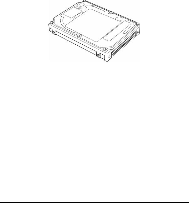
The HDD is shown in Figure 1-4 and some of its specifications are listed in Table 1-1.
Figure 1- 5 2.5-inch HDD
Table 1- 1 2.5-inch HDD specifications
Item |
|
|
Specifications |
|
|
|
|||
|
|
|
|
|
|
|
|
||
Capacity (GB) |
30GB |
40GB |
60GB |
80GB |
|||||
|
|
|
|
|
|
|
|
|
|
Rotational |
|
4200 |
5400 |
4200 |
|
5400 |
4200 |
5400 |
|
speed |
4200rpm |
|
|||||||
rpm |
rpm |
rpm |
|
rpm |
rpm |
rpm |
|||
(RPM) |
|
|
|||||||
|
|
|
|
|
|
|
|
||
|
|
|
|
|
|
|
|
|
|
User data |
58,605,120 |
78,140,160 |
117,210,240 |
156,301,488 |
|||||
sectors |
|||||||||
|
|
|
|
|
|
|
|
||
|
|
|
|
|
|||||
Bytes/sector |
512 |
512 |
512 |
512 |
|||||
|
|
|
|
|
|
|
|
|
|
Equium A60/Satellite A60/ Pro A60/A65 Maintenance Manual |
1-14 |
1.4 DVD-ROM Drive |
1 Hardware Overview |
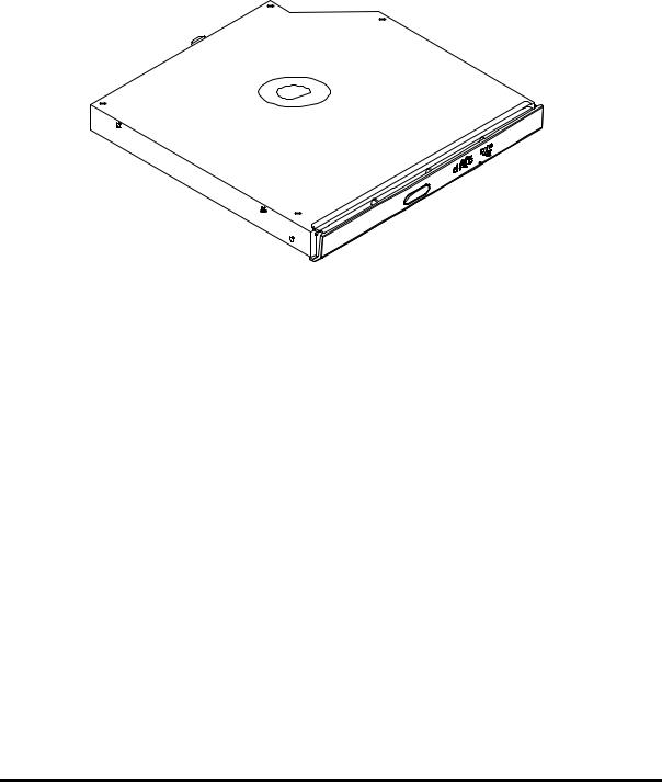
1.4 DVD-ROM Drive
The DVD-ROM drive accepts 12-cm (4.72-inch) and 8-cm (3.15-inch) discs. The drive provides high-speed data transfer, playing back a DVD at up to 8x speed and reading up to 10,820 Kbytes per second from DVD-ROM and 3,600 Kbytes per second from CD-ROM.
The DVD-ROM drive is shown in Figure 1-5 and its specifications are listed in Table 1-2.
Figure 1- 6 DVD-ROM drive
Table 1- 2 DVD-ROM drive specifications
Item |
DVD-ROM |
|
|
Data transfer rate (Mbytes/s) |
33.3 (U-DMA transfer mode 2) |
|
|
Access time (ms) |
|
Average random access (ms) |
100ms |
Average full stroke access (ms) |
|
|
|
Data buffer size (Kbytes) |
192 |
|
|
Formats supported |
DVD-R/W, DVD-R (Read),DVD-RAM |
|
CD-ROM, CD-R, |
|
CD-R (Write), CD-RW (Write) |
|
|
Equium A60/Satellite A60/ Pro A60/A65 Maintenance Manual |
1-15 |

1 Hardware Overview |
1.5 CD-RW/DVD-ROM Drive |
1.5 CD-RW/DVD-ROM Drive
The CD-RW/DVD-ROM drive accepts 12-cm (4.72-inch) and 8-cm (3.15-inch) discs. At maximum, the drive can play back a DVD at 8x speed, read CD-ROM at 24x speed, and write CD-R at 24x speed and CD-RW at 10x speed.
The specifications of the CD-RW/DVD-ROM drive are listed in Table 1-3.
Table 1- 3 CD-RW/DVD-ROM drive specifications
Item |
DVD-ROM mode |
CD-RW mode |
|
|
|
|
|
Data transfer rate |
33.3 (U-DMA transfer mode 2) |
|
|
(Mbytes/s) |
16.7 (PIO mode 4, Multiword DMA mode 2) |
||
|
|||
|
|
|
|
Access time (ms) |
|
|
|
Average random |
120 |
150 |
|
access |
|||
|
|
||
Average full stroke |
|
|
|
access |
|
|
|
|
|
|
|
Data buffer size |
2 |
|
|
(Mbytes) |
|
|
|
|
|
|
|
Formats supported |
DVD: |
|
|
|
DVD-ROM(DVD-5,DVD-9,DVD-10,DVD-18),DVD-R |
||
|
(Ver.1.0,Ver.2.0),DVD-RW(Read Ver.1.1),DVD-RAM(Read Ver.2.1) |
||
|
CD: |
|
|
|
CD-DA,CD+(E)G,CD-MIDI,CD-TEXT,CD-ROM,CD-ROM XA,MIXED |
||
|
MODE CD,CD-I,CD-I Bridge(Photo CD,Video CD),Muitisession |
||
|
CD(Photo CD,CD-EXTRA,Portfolio,CD-R,CD-RW),CD-R,CD-RW |
||
|
|
|
|
1-16 |
Equium A60/Satellite A60/ Pro A60/A65 Maintenance Manual |
Loading...