


TOSHIBA AMERICA INFORMATION SYSTEMS STORAGE DEVICE DIVISION
IRVINE, CALIFORNIA
SD-M1612
DVD-ROM DRIVE
USER MANUAL

CONTENTS |
|
Introduction.............................................................................. |
1 |
Setup ........................................................................................ |
3 |
Using the DVD-ROM Drive ...................................................... |
6 |
Troubleshooting....................................................................... |
9 |
Specifications ........................................................................ |
10 |
Drive Connectors................................................................... |
13 |

INTRODUCTION – SD-M1612 DVD-ROM Drive
General Features
Tray Loading Mechanism
3-way Disc Eject (eject button, software, emergency eject hole)
Average Random Access Time |
|
CD-ROM |
85ms |
DVD |
95ms |
DVD-RAM |
170ms |
DAE (Digital Audio Extraction) Audio Capability
MPC3 Compatibility
Multi-Read Capability
Regionalization (RPC2 compliance) (DVD)
ATAPI BUS Interface:
Drive Speed |
|
|
DVD |
16X |
Single Layer |
|
10X |
Dual Layer |
CD |
48X |
|
DVD-RAM |
2X (ver 1.0) |
|
|
1X (ver 2.1) |
|
Types of Disc Formats Supported
DVD
•DVD-ROM
DVD-5 - Single-sided/Single Layer DVD-9 - Single-sided/Dual Layer DVD-10 - Double-sided/Single Layer DVD-18 - Double-sided/Dual Layer
•DVD-R, DVD-RW, DVD-RAM (Read)
1
CD
•CD-DA
•CD+(E)G
•CD-MIDI
•CD-TEXT
•CD-ROM
•CD-ROM-XA
•CD-I Bridge (Photo-CD, Video CD)
•CD-I
•Multi-session (Photo-CD, CD Extra, CD-RW, CD-R)
•CD-R (Read)
•CD-RW (Read)
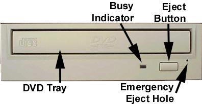
Front Panel
Loading Tray
Busy Indicator
Eject
Button
Emergency
Eject Hole
Figure 1.SD-M1612 DVD-ROM Drive Front Panel
Load disc using tray.
When you install a disc into the DVD-ROM drive, the BUSY light flashes slowly as it attempts to locate the disc. One of the following will occur:
•BUSY light goes out. The DVD-ROM drive is ready to read data from the disc.
•BUSY light flashes slowly. The disc may be dirty.
•BUSY light remains ON. The DVD-ROM is accessing data.
•BUSY light remains ON indefinitely. The DVD-ROM is experiencing an error
The Eject button is used to open the disc tray so you can install or remove a disc.
The emergency eject hole is to be used only when the Loading Tray will not open when Eject button is pressed.

SETUP – SD-M1612 DVD-ROM
The following steps must be performed to properly install your drive:
•Set Drive Jumper Settings
•Connect Audio Cable (optional)
•Attach IDE BUS Cable
•Attach Power Cable
•Mount Drive
Jumper Settings
The mode select jumpers are 6 straight angle pins located on the rear of the DVD-ROM drive. By placing a jumper on the pins, you can select the following functions:
CS |
Drive is configured using host interface signal CSEL |
SL |
Configures drive as Slave |
MA |
Configures drive as Master (default mode) |
|
Figure 1.Mode Select Jumper |
In most installations, jumper should remain in the MA position (factory default). It is recommended that you install your DVD-ROM drive only on the secondary IDE BUS. If you are installing on primary IDE BUS, your hard drive would then be the Master, and you should set your DVD-ROM drive to the Slave position (SL)
Figure 2.Jumper Locations
3
Placing DVD-ROM Drive inside your Computer
Now that you have set the jumpers, you are ready to install your DVD-ROM drive inside your computer.
 Important Note: Disconnect power from your computer system before beginning installation.
Remove computer cover and faceplate if required. Refer to your computer systems manual for removal information. If the DVD-ROM drive is replacing a CD-ROM or DVD-ROM, remove drive presently installed in your system.
Your Toshiba DVD-ROM drive can be placed in any free half-height drive slot at the front of your computer. (It can be mounted horizontally or vertically.)
Carefully start sliding the DVD-ROM drive into the opening with the disc tray facing the front of the computer. Before you push the drive all the way in you will need to connect the IDE BUS cable, Audio cable and the Power cable on the back of the drive.
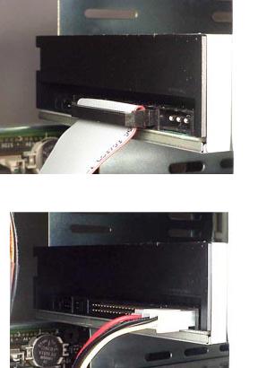
Connecting Cables
IDE BUS Cable (not supplied with drive) - Your computer system should have a primary and secondary IDE BUS, cable with your Hard Drive most likely being the Master on the primary BUS. Connect BUS cable as follows, assuring that pin 1 of cable (side with red stripe) is connected to pin 1 of the DVD-ROM drive's interface connector:
If you are replacing your CD-ROM or DVD:
connect DVD-ROM drive to the BUS Cable connector that the CD-ROM or DVD was connected to.
If DVD-ROM drive is not replacing a CD-ROM/DVD or is an addition to a CD-ROM/DVD:
connect DVD-ROM drive to an open connector on the secondary IDE BUS cable (not supplied with drive).
If DVD-ROM drive is to be slave on Primary BUS: connect DVD-ROM drive to open connector on the primary IDE BUS cable (not supplied with drive).
Figure 3.Installing BUS Cable
Power Cable - Connect an internal computer power supply cable to the power socket at the back of the DVD-ROM drive. One side of the plug has chamfered edges, so the power connector fits only one way. Push plug completely into the socket making sure the plug fits correctly.
Figure 4.Installing Power Cable
4
 Loading...