


FILE NO. A09-010
SERVICE MANUAL
AIR-CONDITIONER
SPLIT TYPE
OUTDOOR UNIT
<SUPER DIGITAL INVERTER>
RAV-SP180AT2-UL RAV-SP240AT2-UL RAV-SP300AT2-UL RAV-SP360AT2-UL RAV-SP420AT2-UL
(2 HP)
(3 HP)
(4 HP)
(4, 5 HP)
(5 HP)
R410A
PRINTED IN JAPAN, Dec., 2009 ToMo

Adoption of New Refrigerant
This Air Conditioner is a new type which adopts a new refrigerant HFC (R410A) instead of the conventional refrigerant R22 in order to prevent destruction of the ozone layer.
WARNING
Cleaning of the air filter and other parts of the air filter involves dangerous work in high places, so be sure to have a service person do it. Do not attempt it yourself.
The cleaning diagram for the air filter is there for the service person, and not for the customer.
– 2 –
CONTENTS
SAFETY CAUTION ............................................................................................ |
4 |
||
1. |
SPECIFICATIONS ...................................................................................... |
9 |
|
|
1-1. |
Outdoor Unit........................................................................................................ |
9 |
|
1-2. |
Operation Characteristic Curve....................................................................... |
10 |
2. |
CONSTRUCTION VIEWS (EXTERNAL VIEWS)....................................... |
12 |
|
|
2-1. |
Outdoor Unit...................................................................................................... |
12 |
3. |
SYSTEMATIC REFRIGERATING CYCLE DIAGRAM .............................. |
15 |
|
|
3-1. |
Indoor Unit......................................................................................................... |
15 |
|
3-2. |
Outdoor Unit...................................................................................................... |
16 |
4. |
WIRING DIAGRAM ................................................................................... |
19 |
|
|
4-1. |
Outdoor Unit...................................................................................................... |
19 |
5. |
SPECIFICATIONS OF ELECTRICAL PARTS .......................................... |
22 |
|
|
5-1. |
Outdoor Unit (Parts Ratings) ........................................................................... |
22 |
6. |
REFRIGERANT R410A ............................................................................ |
23 |
|
|
6-1. |
Safety During Installation/Servicing ............................................................... |
23 |
|
6-2. |
Refrigerant Piping Installation....................................................................... |
23 |
|
6-3. |
Tools .................................................................................................................. |
27 |
|
6-4. |
Recharging of Refrigerant................................................................................ |
27 |
|
6-5. |
Brazing of Pipes................................................................................................ |
28 |
7. |
CIRCUIT CONFIGURATION AND CONTROL SPECIFICATIONS ........... |
30 |
|
|
7-1. |
Print Circuit Board <MCC-1571> ..................................................................... |
30 |
|
7-2. |
Outline of Main Controls .................................................................................. |
32 |
8. |
TROUBLESHOOTING .............................................................................. |
45 |
|
|
8-1. |
Summary of Troubleshooting........................................................................... |
45 |
|
8-2. |
Troubleshooting ................................................................................................ |
47 |
9. |
REPLACEMENT OF SERVICE P.C. BOARD............................................ |
73 |
|
|
9-1. |
Outdoor Unit...................................................................................................... |
73 |
10. |
SETUP AT LOCAL SITE AND OTHERS .................................................. |
74 |
|
|
10-1. |
Outdoor Unit...................................................................................................... |
74 |
11. |
DETACHMENTS ....................................................................................... |
82 |
|
|
11-1. |
Outdoor Unit..................................................................................................... |
82 |
12. |
EXPLODED VIEWS AND PARTS LIST .................................................. |
106 |
|
|
12-1. |
Outdoor Unit.................................................................................................... |
106 |
– 3 –
SAFETY CAUTION
The important contents concerned to the safety are described on the product itself and on this Service Manual.
Please read this Service Manual after understanding the described items thoroughly in the following contents (Indications/Illustrated marks), and keep them.
[Explanation of indications]
Indication |
Explanation |
|
|
DANGER |
Indicates contents assumed that an imminent danger causing a death or serious injury of |
the repair engineers and the third parties when an incorrect work has been executed. |
Indicates possibilities assumed that a danger causing a death or serious injury of the WARNING repair engineers, the third parties, and the users due to troubles of the product after work
when an incorrect work has been executed.
Indicates contents assumed that an injury or property damage ( ) may be caused on the CAUTION repair engineers, the third parties, and the users due to troubles of the product after work
when an incorrect work has been executed.
Property damage : Enlarged damage concerned to property, furniture, and domestic animal/pet
[Explanation of illustrated marks]
Mark |
Explanation |
Indicates prohibited items (Forbidden items to do)
The sentences near an illustrated mark describe the concrete prohibited contents.
Indicates mandatory items (Compulsory items to do)
The sentences near an illustrated mark describe the concrete mandatory contents.
Indicates cautions (Including danger/warning)
The sentences or illustration near or in an illustrated mark describe the concrete cautious contents.
[Confirmation of warning label on the main unit]
Confirm that labels are indicated on the specified positions (Refer to the Parts disassembly diagram (Outdoor unit).)
If removing the label during parts replace, stick it as the original.
 DANGER
|
Turn “OFF” the breaker before removing the front panel and cabinet, otherwise an electric |
|
shock is caused by high voltage resulted in a death or injury. |
|
During operation, a high voltage with 400V or higher of circuit ( ) at secondary circuit of the |
|
high-voltage transformer is applied. |
Turn off breaker. |
If touching a high voltage with the naked hands or body, an electric shock is caused even if using an |
electric insulator. |
|
|
: For details, refer to the electric wiring diagram. |
|
When removing the front panel or cabinet, execute short-circuit and discharge between |
|
|
high-voltage capacitor terminals. |
|
Execute discharge |
If discharge is not executed, an electric shock is caused by high voltage resulted in a death or injury. |
|
After turning off the breaker, high voltage also keeps to apply to the high-voltage capacitor. |
||
between terminals. |
Do not turn on the breaker under condition that the front panel and cabinet are removed.
An electric shock is caused by high voltage resulted in a death or injury.
Prohibition
– 4 –

 WARNING
|
Before troubleshooting or repair work, check the earth wire is connected to the earth |
|
|
terminals of the main unit, otherwise an electric shock is caused when a leak occurs. |
|
Check earth wires. |
If the earth wire is not correctly connected, contact an electric engineer for rework. |
|
|
||
|
|
|
|
Do not modify the products. |
|
|
Do not also disassemble or modify the parts. It may cause a fire, electric shock or injury. |
|
Prohibition of modification. |
|
|
|
For spare parts, use those specified ( ). |
|
|
If unspecified parts are used, a fire or electric shock may be caused. |
|
Use specified parts. |
: For details, refer to the parts list. |
|
|
|
|
|
Before troubleshooting or repair work, do not bring a third party (a child, etc.) except |
|
|
the repair engineers close to the equipment. |
|
Do not bring a child |
It causes an injury with tools or disassembled parts. |
|
Please inform the users so that the third party (a child, etc.) does not approach the equipment. |
||
close to the equipment. |
||
|
|
|
|
Connect the cut-off lead wires with crimp contact, etc, put the closed end side |
|
|
upward and then apply a water-cut method, otherwise a leak or production of fire is |
|
|
caused at the users’ side. |
|
Insulating measures |
|
When repairing the refrigerating cycle, take the following measures.
1)Be attentive to fire around the cycle. When using a gas stove, etc, be sure to put out fire before work; otherwise the oil mixed with refrigerant gas may catch fire.
|
2) Do not use a welder in the closed room. |
No fire |
When using it without ventilation, carbon monoxide poisoning may be caused. |
3)Do not bring inflammables close to the refrigerant cycle, otherwise fire of the welder may catch the inflammables.
|
Check the used refrigerant name and use tools and materials of the parts which |
|
|
match with it. |
|
|
For the products which use R410A refrigerant, the refrigerant name is indicated at a |
|
|
position on the outdoor unit where is easy to see. To prevent miss-charging, the route of the |
|
|
service port is changed from one of the former R22. |
|
|
For an air conditioner which uses R410A, never use other refrigerant than R410A. |
|
|
For an air conditioner which uses other refrigerant (R22, etc.), never use R410A. |
|
|
If different types of refrigerant are mixed, abnormal high pressure generates in the |
|
|
refrigerating cycle and an injury due to breakage may be caused. |
|
|
Do not charge refrigerant additionally. |
|
|
If charging refrigerant additionally when refrigerant gas leaks, the refrigerant composition in |
|
|
the refrigerating cycle changes resulted in change of air conditioner characteristics or |
|
|
refrigerant over the specified standard amount is charged and an abnormal high pressure is |
|
|
applied to the inside of the refrigerating cycle resulted in cause of breakage or injury. |
|
|
Therefore if the refrigerant gas leaks, recover the refrigerant in the air conditioner, execute |
|
Refrigerant |
vacuuming, and then newly recharge the specified amount of liquid refrigerant. |
|
In this time, never charge the refrigerant over the specified amount. |
||
|
||
|
When recharging the refrigerant in the refrigerating cycle, do not mix the refrigerant |
|
|
or air other than R410A into the specified refrigerant. |
|
|
If air or others is mixed with the refrigerant, abnormal high pressure generates in the |
|
|
refrigerating cycle resulted in cause of injury due to breakage. |
|
|
After installation work, check the refrigerant gas does not leak. |
|
|
If the refrigerant gas leaks in the room, poisonous gas generates when gas touches to fire |
|
|
such as fan heater, stove or cocking stove though the refrigerant gas itself is innocuous. |
|
|
Never recover the refrigerant into the outdoor unit. |
|
|
When the equipment is moved or repaired, be sure to recover the refrigerant with |
|
|
recovering device. The refrigerant cannot be recovered in the outdoor unit; otherwise a |
|
|
serious accident such as breakage or injury is caused. |
|
|
|
|
|
After repair work, surely assemble the disassembled parts, and connect and lead the |
|
|
removed wires as before. Perform the work so that the cabinet or panel does not |
|
|
catch the inner wires. |
|
Assembly/Cabling |
If incorrect assembly or incorrect wire connection was done, a disaster such as a leak or |
|
fire is caused at user’s side. |
||
|
– 5 –
 WARNING
|
After the work has finished, be sure to use an insulation tester set (500V Megger) to |
|
|
check the resistance is 2MΩ or more between the charge section and the non-charge |
|
|
metal section (Earth position). |
|
Insulator check |
If the resistance value is low, a disaster such as a leak or electric shock is caused at user’s |
|
side. |
||
|
||
|
|
|
|
When the refrigerant gas leaks during work, execute ventilation. |
|
|
If the refrigerant gas touches to a fire, poisonous gas generates. |
|
|
A case of leakage of the refrigerant and the closed room full with gas is dangerous because |
|
Ventilation |
a shortage of oxygen occurs. Be sure to execute ventilation. |
|
|
|
|
|
When checking the circuit inevitably under condition of the power-ON, use rubber |
|
|
gloves and others not to touch to the charging section. |
|
|
If touching to the charging section, an electric shock may be caused. |
|
Be attentive to |
|
|
electric shock |
|
|
|
|
|
|
When the refrigerant gas leaks, find up the leaked position and repair it surely. |
|
|
If the leaked position cannot be found up and the repair work is interrupted, pump-down |
|
|
and tighten the service valve, otherwise the refrigerant gas may leak into the room. |
|
|
The poisonous gas generates when gas touches to fire such as fan heater, stove or cocking |
|
|
stove though the refrigerant gas itself is innocuous. |
|
|
When installing equipment which includes a large amount of charged refrigerant |
|
|
such as a multi air conditioner in a sub-room, it is necessary that the density does |
|
|
not the limit even if the refrigerant leaks. |
|
Compulsion |
If the refrigerant leaks and exceeds the limit density, an accident of shortage of oxygen is |
|
|
caused. |
|
|
For the installation/moving/reinstallation work, follow to the Installation Manual. |
|
|
If an incorrect installation is done, a trouble of the refrigerating cycle, water leak, electric |
|
|
shock or fire is caused. |
|
|
|
|
|
After repair work has finished, check there is no trouble. |
|
|
If check is not executed, a fire, electric shock or injury may be caused. |
|
|
For a check, turn off the power breaker. |
|
Check after repair |
|
|
|
|
|
|
After repair work (installation of front panel and cabinet) has finished, execute a test |
|
|
run to check there is no generation of smoke or abnormal sound. |
|
|
If check is not executed, a fire or an electric shock is caused. |
|
|
Before test run, install the front panel and cabinet. |
Check the following items after reinstallation.
Check after reinstallation |
1) |
The earth wire is correctly connected. |
|
||
|
2) |
The power cord is not caught in the product. |
|
3) |
There is no inclination or unsteadiness and the installation is stable. |
|
|
If check is not executed, a fire, an electric shock or an injury is caused. |
 CAUTION
|
Be sure to put on the gloves ( ) and a long sleeved shirt: |
|
otherwise an injury may be caused with the parts, etc. |
Put on gloves |
( ) Heavy gloves such as work gloves |
|
|
|
|
|
When the power was turned on, start to work after the equipment has been |
|
sufficiently cooled. |
Cooling check |
As temperature of the compressor pipes and others became high due to cooling/heating |
operation, a burn may be caused. |
|
|
|
– 6 –

• New Refrigerant (R410A)
This air conditioner adopts a new HFC type refrigerant (R410A) which does not deplete the ozone layer.
1. Safety Caution Concerned to New Refrigerant
The pressure of R410A is high 1.6 times of that of the former refrigerant (R22). Accompanied with change of refrigerant, the refrigerating oil has been also changed.
Therefore, be sure that water, dust, the former refrigerant or the former refrigerating oil is not mixed into the refrigerating cycle of the air conditioner with new refrigerant during installation work or service work.
If an incorrect work or incorrect service is performed, there is a possibility to cause a serious accident. Use the tools and materials exclusive to R410A to purpose a safe work.
2.Cautions on Installation/Service
1)Do not mix the other refrigerant or refrigerating oil.
For the tools exclusive to R410A, shapes of all the joints including the service port differ from those of the former refrigerant in order to prevent mixture of them.
2)As the use pressure of the new refrigerant is high, use material thickness of the pipe and tools which are specified for R410A.
3)In the installation time, use clean pipe materials and work with great attention so that water and others do not mix in because pipes are affected by impurities such as water, oxide scales, oil, etc.
Use the clean pipes.
Be sure to brazing with flowing nitrogen gas. (Never use gas other than nitrogen gas.)
4)For the earth protection, use a vacuum pump for air purge.
5)R410A refrigerant is azeotropic mixture type refrigerant.
Therefore use liquid type to charge the refrigerant. (If using gas for charging, composition of the refrigerant changes and then characteristics of the air conditioner change.)
3.Pipe Materials
For the refrigerant pipes, copper pipe and joints are mainly used.
It is necessary to select the most appropriate pipes to conform to the standard.
Use clean material in which impurities adhere inside of pipe or joint to a minimum.
1) Copper pipe
<Piping>
The pipe thickness, flare finishing size, flare nut and others differ according to a refrigerant type.
When using a long copper pipe for R410A, it is recommended to select “Copper or copper-base pipe without seam” and one with bonded oil amount 0.0001 lbs / 32’ 10” (40 mg / 10 m) or less.
Also do not use crushed, deformed, discolored (especially inside) pipes. (Impurities cause clogging of expansion valves and capillary tubes.)
<Flare nut>
Use the flare nuts which are attached to the air conditioner unit.
2)Joint
The flare joint and socket joint are used for joints of the copper pipe.
The joints are rarely used for installation of the air conditioner. However clear impurities when using them.
–7 –
4.Tools
1.Required Tools for R410A
Mixing of different types of oil may cause a trouble such as generation of sludge, clogging of capillary, etc. Accordingly, the tools to be used are classified into the following three types.
1)Tools exclusive for R410A (Those which cannot be used for conventional refrigerant (R22))
2)Tools exclusive for R410A, but can be also used for conventional refrigerant (R22)
3)Tools commonly used for R410A and for conventional refrigerant (R22)
The table below shows the tools exclusive for R410A and their interchangeability.
Tools exclusive for R410A (The following tools for R410A are required.)
Tools whose specifications are changed for R410A and their interchangeability
|
|
|
R410A |
Conventional air |
||
|
|
|
air conditioner installation |
conditioner installation |
||
No. |
Used tool |
Usage |
|
|
|
|
Existence of |
Whether conven- |
Whether conventional |
||||
|
|
|
||||
|
|
|
new equipment |
tional equipment |
||
|
|
|
equipment can be used |
|||
|
|
|
for R410A |
can be used |
||
|
|
|
|
|||
|
|
|
|
|
|
|
Q |
Flare tool |
Pipe flaring |
Yes |
*(Note) |
Yes |
|
|
|
|
|
|
|
|
R |
Copper pipe gauge for |
Flaring by conventional |
Yes |
*(Note) |
*(Note) |
|
adjusting projection margin |
flare tool |
|||||
|
|
|
|
|
|
|
S |
Torque wrench |
Tightening of flare nut |
Yes |
No |
No |
|
|
|
|
|
|
|
|
T |
Gauge manifold |
Evacuating, refrigerant |
Yes |
No |
No |
|
|
|
|||||
U |
Charge hose |
charge, run check, etc. |
||||
|
|
|
||||
|
|
|
|
|||
|
|
|
|
|
|
|
V |
Vacuum pump adapter |
Vacuum evacuating |
Yes |
No |
Yes |
|
|
|
|
|
|
|
|
W |
Electronic balance for |
Refrigerant charge |
Yes |
Yes |
Yes |
|
refrigerant charging |
||||||
|
|
|
|
|
|
|
X |
Refrigerant cylinder |
Refrigerant charge |
Yes |
No |
No |
|
|
|
|
|
|
|
|
Y |
Leakage detector |
Gas leakage check |
Yes |
No |
Yes |
|
|
|
|
|
|
|
|
NOTE
When flaring is carried out for R410A using the conventional flare tools, adjustment of projection margin is necessary. For this adjustment, a copper pipe gauge, etc. are necessary.
General tools (Conventional tools can be used.)
In addition to the above exclusive tools, the following equipments which serve also for R22 are necessary as the general tools.
1) Vacuum pump. Use vacuum pump by attaching vacuum pump adapter.
2) |
Torque wrench |
8) |
Spanner or Monkey wrench |
3) |
Pipe cutter |
9) |
Hole core drill |
4) |
Reamer |
10) |
Hexagon wrench (Opposite side 4mm) |
5) |
Pipe benderr |
11) |
Tape measure |
6) |
Level vial |
12) |
Metal saw |
7) |
Screwdriver (+, –) |
|
|
Also prepare the following equipments for other installation method and run check.
1) |
Clamp meter |
3) |
Insulation resistance tester (Megger) |
2) |
Thermometer |
4) |
Electroscope |
– 8 –
1. SPECIFICATIONS
1-1. Outdoor Unit
<Super Digital Inverter>
Size |
|
|
|
018 |
024 |
030 |
|
036 |
|
042 |
|
|
|
|
|
|
|
|
|
|
|
|
|
Outdoor model |
|
|
RAV- |
SP180AT2-UL |
SP240AT2-UL |
SP300AT2-UL |
SP360AT2-UL |
|
SP420AT2-UL |
||
|
|
|
|
|
|
|
|
|
|
|
|
|
|
|
Outdoor Min - Max DB 1 |
(°F) |
|
|
23 to 109.4 |
|
|
|
|
|
|
|
|
|
|
|
|
|
|
|
|
|
|
Cooling |
Indoor Min - Max DB |
(°F) |
|
|
69.8 to 89.6 |
|
|
|
|
Operating |
|
|
|
|
|
|
|
|
|
|
|
|
|
Indoor Min - Max WB |
(°F) |
|
|
59 to 75.2 |
|
|
|
||
range |
|
|
|
|
|
|
|
||||
|
|
|
|
|
|
|
|
|
|
|
|
|
|
|
|
|
|
|
|
|
|
|
|
|
|
|
Outdoor WB Min - Max |
(°F) |
|
|
–4 to 59 |
|
|
|
|
|
|
Heating |
|
|
|
|
|
|
|
|
|
|
|
Indoor DB Min - Max |
(°F) |
|
|
59 to 86 |
|
|
|
||
|
|
|
|
|
|
|
|
||||
|
|
|
|
|
|
|
|
|
|
|
|
|
|
Standard Piping Length |
(ft.) |
|
|
25 |
|
|
|
|
|
|
|
|
|
|
|
|
|
|
|
|
|
|
|
Min. Piping Length |
(ft.) |
16’ 5” |
16’ 5” |
9’ 8” |
|
9’ 8” |
|
9’ 8” |
|
|
|
|
|
|
|
|
|
|
|
|
|
|
|
Max. Piping Length |
(ft.) |
164’ 1” |
164’ 1” |
246’ 1” |
|
246’ 1” |
|
246’ 1” |
|
|
|
|
|
|
|
|
|
|
|
|
|
|
|
Lift |
(Outdoor below Indoor) |
(ft.) |
|
|
98’ 5” |
|
|
|
|
Piping |
|
|
|
|
|
|
|
|
|
|
|
|
Lift |
(Outdoor above Indoor) |
(ft.) |
|
|
98’ 5” |
|
|
|
||
|
|
|
|
|
|
|
|||||
|
|
|
|
|
|
|
|
|
|
|
|
|
|
Gas Pipe |
(Size / connection type) |
|
1/2” |
5/8” |
5/8” |
|
5/8” |
|
5/8” |
|
|
|
|
|
|
|
|
|
|
|
|
|
|
Liquid Pipe |
(Size / connection type) |
|
1/4” |
3/8” |
3/8” |
|
3/8” |
|
3/8” |
|
|
|
|
|
|
|
|
|
|
|
|
|
|
Additional refrigerant charge |
|
0.22 oz / ft |
0.43 oz / ft |
|
|
0.43 oz / ft |
|
||
|
|
under long piping connection |
|
(65’7”ft to164’1”ft) |
(98’5”ft to 164’1”ft) |
(98’5”ft to 246’1”ft) |
|
||||
|
|
|
|
|
|
|
|
|
|
|
|
|
|
Voltage |
|
|
|
208 V / 230 V-1-60 Hz |
|
|
|
||
|
|
|
|
|
|
|
|
|
|
|
|
Electrical |
|
Maximum Running Current Amps |
(A) |
17 |
24 |
24 |
|
24 |
|
24 |
|
|
|
|
|
|
|
|
|
|
|
|
|
|
|
Fuse Rating 2 |
|
30 |
40 |
40 |
|
40 |
|
40 |
|
|
|
|
|
|
|
|
|
|
|
|
|
|
|
Type |
|
|
|
Hermetic compressor |
|
|
|
||
|
|
|
|
|
|
|
|
|
|
|
|
Compressor |
|
Motor |
|
(kw) |
1.1 |
2 |
3.75 |
|
3.75 |
|
3.75 |
|
|
|
|
|
|
|
|
|
|
|
|
|
|
Pole |
|
|
4 |
4 |
4 |
|
4 |
|
4 |
|
|
|
|
|
|
|
|
|
|
|
|
|
|
|
Height |
(in.) |
21.7 |
35.0 |
52.8 |
|
52.8 |
|
52.8 |
|
|
|
|
|
|
|
|
|
|
|
|
|
|
Dimensions |
Width |
(in.) |
30.7 |
35.4 |
35.4 |
|
35.4 |
|
35.4 |
|
|
|
|
|
|
|
|
|
|
|
|
|
|
|
Length |
(in.) |
11.4 |
12.6 |
12.6 |
|
12.6 |
|
12.6 |
|
|
|
|
|
|
|
|
|
|
|
|
Outdoor |
|
Weight -Gross / Net |
(lbs.) |
98 / 105 |
144.5 / 157 |
211.5 / 226 |
|
211.5 / 226 |
|
211.5 / 226 |
|
|
|
|
|
|
|
|
|
|
|
|
|
|
|
Refrigerant charged |
|
3.1 |
4.6 |
6.8 |
|
6.8 |
|
6.8 |
|
|
|
|
|
|
|
|
|
|
|
|
|
|
|
Appearance |
(Munsell symbol) |
|
|
Silky shade (Muncel 1Y8.5/0.5) |
|
||||
|
|
|
|
|
|
|
|
|
|
|
|
|
|
Sound Pressure |
(dBa) |
48 / 49 |
49 / 50 |
50 / 51 |
|
52 / 52 |
|
52 / 52 |
|
|
|
|
|
|
|
|
|
|
|
|
|
1 When installed a duct or wind shield so that it is not affected by the wind. The minimum outside temperature will be 5°F
2 UL value
– 9 –
1-2. Operation Characteristic CurveRAV*
• Operation characteristic curve <Super Digital Inverter>
RAV-SP180AT2-UL
<Cooling>
|
10 |
|
|
|
|
|
|
|
|
|
|
|
|
|
|
|
|
|
|
|
|
|
|
|
9 |
|
|
|
|
|
|
|
|
|
|
|
8 |
|
RAV-SP180CT, KRT-UL |
|
|
|
|
||||
|
7 |
|
|
|
|
|
|
|
|
|
|
(A) |
6 |
|
|
|
|
|
|
|
|
|
|
|
|
|
|
|
|
|
|
|
|
|
|
Current |
5 |
|
|
|
|
|
|
|
|
|
|
|
|
|
|
|
|
|
|
|
|
|
|
|
4 |
|
|
|
|
|
|
|
|
|
|
|
|
|
|
|
|
RAV-SP180UT-UL |
|
|
|||
|
3 |
|
|
|
|
|
|
|
|
|
|
|
|
|
|
|
|
• Conditions |
|
|
|
|
|
|
2 |
|
|
|
|
Indoor |
: DB 80.6˚F (27˚C)/ |
|
|
||
|
|
|
|
|
|
WB 66.2˚F (19˚C) |
|
|
|||
|
|
|
|
|
|
Outdoor : DB 95˚F (35˚C) |
|
|
|||
|
1 |
|
|
|
|
Air flow |
: High |
|
|
|
|
|
|
|
|
|
Pipe length : 295.3” (7.5m) |
|
|
||||
|
|
|
|
|
|
230V |
|
|
|
|
|
|
0 |
|
|
|
|
|
|
|
|
|
|
|
|
|
|
|
|
|
|
|
|
|
|
|
|
10 |
20 |
30 |
40 |
50 |
60 |
70 |
80 |
||
|
0 |
||||||||||
<Heating>
|
16 |
|
|
|
|
|
|
|
|
|
|
|
|
|
|
|
|
|
|
|
|
|
|
|
|
|
|
|
|
|
14 |
|
|
|
|
|
|
|
|
|
|
|
|
|
|
|
|
RAV-SP180CT, KRT-UL |
|
|
|
|
|||||||
|
12 |
|
|
|
|
|
|
|
|
|
|
|
|
|
|
10 |
|
|
|
|
|
|
|
|
|
|
|
|
|
(A) |
|
|
|
|
|
|
|
|
|
|
|
|
|
|
Current |
8 |
|
|
|
|
|
|
|
|
|
|
|
|
|
|
|
|
|
|
|
|
|
|
|
|
|
|
|
|
|
6 |
|
|
|
|
|
|
|
RAV-SP180UT-UL |
|
||||
|
|
|
|
|
|
|
|
|
|
|||||
|
4 |
|
|
|
|
|
|
|
|
|
|
|
||
|
|
|
|
|
|
|
|
• Conditions |
|
|
|
|||
|
|
|
|
|
|
|
|
|
Indoor |
: DB 68˚F (20˚C) |
|
|
||
|
|
|
|
|
|
|
|
|
Outdoor : DB 44.6˚F (7˚C)/ |
|
|
|||
|
|
|
|
|
|
|
|
|
|
|
WB 42.8˚F (6˚C) |
|
|
|
|
2 |
|
|
|
|
|
|
|
Air flow : High |
|
|
|
||
|
|
|
|
|
|
|
|
|
Pipe length : 295.3” (7.5m) |
|
|
|||
|
|
|
|
|
|
|
|
|
230V |
|
|
|
|
|
|
0 |
|
|
|
|
|
|
|
|
|
|
|
|
|
|
|
|
|
|
|
|
|
|
|
|
|
|
|
|
|
|
10 |
20 |
30 |
40 |
50 |
60 |
70 |
80 |
90 100 110 120 |
||||
|
0 |
|||||||||||||
Compressor speed (rps)
RAV-SP240AT2-UL
<Cooling>
|
13 |
|
|
|
|
|
|
|
|
|
|
|
|
|
|
|
|
|
|
|
|
|
|
|
12 |
|
|
|
|
|
|
|
|
|
|
|
11 |
|
RAV-SP240CT, KRT-UL |
|
|
|
|
|
|||
|
10 |
|
|
|
|
|
|
||||
|
|
|
|
|
|
|
|
|
|
|
|
|
9 |
|
|
|
|
|
|
|
|
|
|
(A) |
8 |
|
|
|
|
|
|
|
|
|
|
7 |
|
|
|
|
|
|
|
|
|
|
|
Current |
|
|
|
|
|
|
|
|
|
|
|
6 |
|
|
|
|
RAV-SP240UT-UL |
|
|
||||
|
|
|
|
|
|
|
|
|
|
|
|
|
5 |
|
|
|
|
|
|
|
|
|
|
|
4 |
|
|
|
|
|
|
|
|
|
|
|
3 |
|
|
|
|
• Conditions |
|
|
|
|
|
|
|
|
|
|
Indoor |
: DB 80.6˚F (27˚C)/ |
|
|
|||
|
|
|
|
|
|
|
WB 66.2˚F (19˚C) |
|
|
||
|
2 |
|
|
|
|
Outdoor : DB 95˚F (35˚C) |
|
|
|||
|
|
|
|
|
|
Air flow |
: High |
|
|
|
|
|
1 |
|
|
|
|
Pipe length : 295.3” (7.5m) |
|
|
|||
|
|
|
|
|
230V |
|
|
|
|
|
|
|
|
|
|
|
|
|
|
|
|
|
|
|
0 |
|
|
|
|
|
|
|
|
|
|
|
|
|
|
|
|
|
|
|
|
|
|
|
|
10 |
20 |
30 |
40 |
50 |
60 |
70 |
80 |
||
|
0 |
||||||||||
Compressor speed (rps)
Compressor speed (rps)
<Heating>
|
22 |
|
|
|
|
|
|
|
|
|
20 |
|
|
|
|
|
RAV-SP240CT, KRT-UL |
||
|
18 |
|
|
|
|
16 |
|
|
|
|
14 |
|
|
|
(A) |
12 |
|
|
|
Current |
|
|
|
|
10 |
|
RAV-SP240UT-UL |
||
|
|
|||
|
|
|
||
|
8 |
|
|
|
|
6 |
|
|
|
|
|
• Conditions |
|
|
|
|
|
|
|
|
|
|
Indoor : DB 68˚F (20˚C) |
|
|
4 |
|
Outdoor : DB 44.6˚F (7˚C)/ |
|
|
|
|
WB 42.8˚F (6˚C) |
|
|
|
|
Air flow : High |
|
|
2 |
|
Pipe length : 295.3” (7.5m) |
|
|
|
|
230V |
|
0
0 10 20 30 40 50 60 70 80 90 100 110 120
Compressor speed (rps)
– 10 –
RAV-SP300AT2-UL, RAV-SP360AT2-UL, RAV-SP420AT2-UL |
|
|
|
|
|||||||
<Cooling> |
|
|
|
<Heating> |
|
|
|
||||
|
22 |
|
|
|
|
|
22 |
|
|
|
|
|
20 |
|
|
|
|
|
20 |
|
|
|
|
|
18 |
RAV-SP360AT2-UL, |
|
|
|
18 |
RAV-SP300AT2-UL |
|
|
||
|
|
RAV-SP420AT2-UL |
|
|
|
|
|
|
|
|
|
|
16 |
|
|
|
|
|
16 |
|
|
|
|
|
14 |
|
|
|
|
|
14 |
|
|
|
|
(A) |
12 |
|
|
|
|
(A) |
12 |
|
|
|
|
Current |
|
|
|
|
Current |
|
|
|
|
||
10 |
|
|
|
|
10 |
|
RAV-SP360AT2-UL, |
||||
|
|
|
|
|
RAV-SP420AT2-UL |
|
|||||
|
|
|
|
|
|
|
|
||||
|
|
|
|
|
|
|
|
|
|
||
|
8 |
|
RAV-SP300AT2-UL |
|
|
8 |
|
|
|
|
|
|
|
|
|
|
|
|
|
|
|
||
|
6 |
|
• Conditions |
|
|
6 |
|
• Conditions |
|
||
|
|
|
|
|
|
|
|
||||
|
4 |
|
Indoor |
: DB 80.6˚F (27˚C)/ |
|
|
4 |
|
Indoor |
: DB 68˚F (20˚C) |
|
|
|
|
WB 66.2˚F (19˚C) |
|
|
|
Outdoor : DB 44.6˚F (7˚C)/ |
|
|||
|
|
|
Outdoor : DB 95˚F (35˚C) |
|
|
|
|
|
WB 42.8˚F (6˚C) |
|
|
|
2 |
|
Air flow |
: High |
|
|
2 |
|
Air flow |
: High |
|
|
|
Pipe length : 295.3” (7.5m) |
|
|
|
Pipe length : 295.3” (7.5m) |
|
||||
|
|
|
230V |
|
|
|
|
|
230V |
|
|
|
0 |
20 |
40 |
60 |
80 |
|
0 |
20 |
40 |
60 |
80 |
|
0 |
|
0 |
||||||||
Compressor speed (rps) |
Compressor speed (rps) |
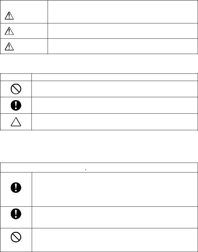
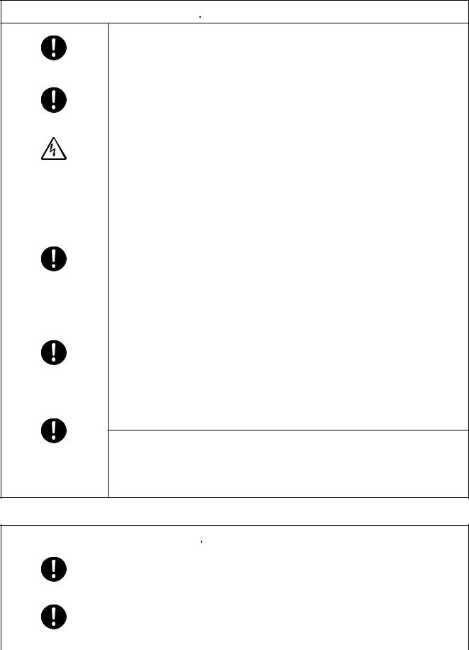
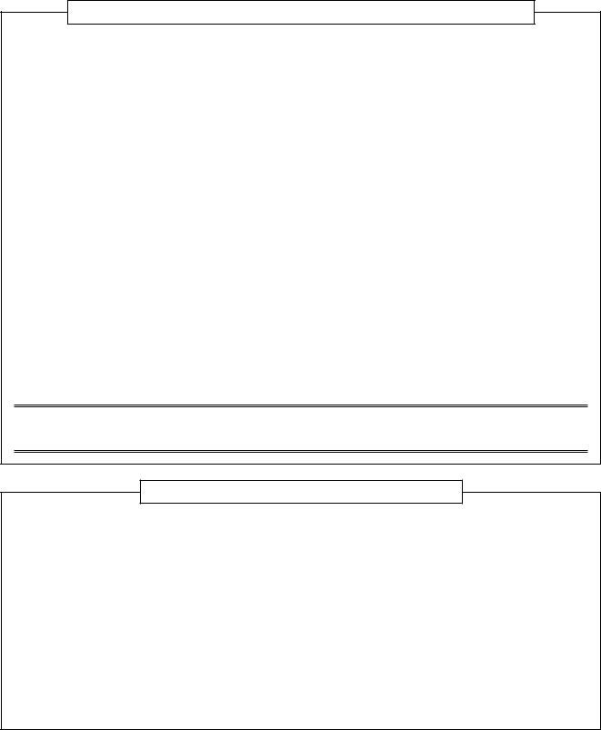
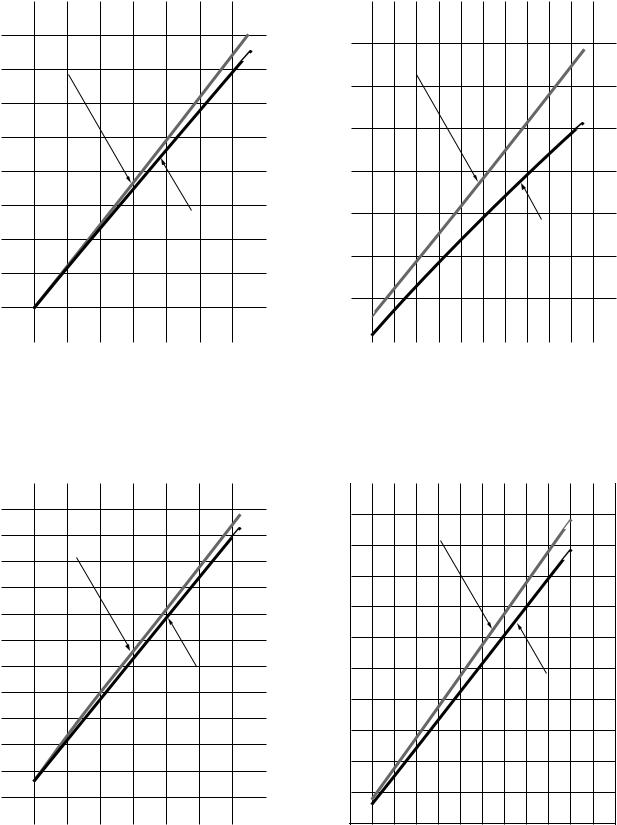
• Capacity variation ratio according to temperature
RAV-SP180AT2-UL, RAV-SP240AT2-UL, RAV-SP300AT2-UL, RAV-SP360AT2-UL, RAV-SP420AT2-UL |
|
||||||||||||||||||||||||||||
<Cooling> |
|
|
|
|
|
|
|
|
|
|
<Heating> |
|
|
|
|
|
|
|
|
|
|
|
|
|
|
||||
|
105 |
|
|
|
|
|
|
|
|
|
|
|
|
120 |
|
|
|
|
|
|
|
|
|
|
|
|
|
|
|
|
100 |
|
|
|
|
|
|
|
|
|
|
|
|
110 |
|
|
|
|
|
|
|
|
|
|
|
|
|
|
|
|
95 |
|
|
|
|
|
|
|
|
|
|
|
|
100 |
|
|
|
|
|
|
|
|
|
|
|
|
|
|
|
|
|
|
|
|
|
|
|
|
|
|
|
|
|
|
|
|
|
|
|
|
|
|
|
|
|
|
|
|
|
|
90 |
|
|
|
|
|
|
|
|
|
|
|
|
90 |
|
|
|
|
|
|
|
|
|
|
|
|
|
|
|
|
|
|
|
|
|
|
|
|
|
|
|
|
|
|
|
|
|
|
|
|
|
|
|
|
|
|
|
|
|
(%) |
85 |
|
|
|
|
|
|
|
|
|
|
|
(%) |
80 |
|
|
|
|
|
|
|
|
|
|
|
|
|
|
|
|
|
|
|
|
|
|
|
|
|
|
|
|
|
|
|
|
|
|
|
|
|
|
|
|
|
|
|||
|
|
|
|
|
|
|
|
|
|
|
|
70 |
|
|
|
|
|
|
|
|
|
|
|
|
|
|
|
||
ratio |
80 |
|
|
|
|
|
|
|
|
|
|
|
ratio |
|
|
|
|
|
|
|
|
|
|
|
|
|
|
|
|
|
|
|
|
|
|
|
|
|
|
|
|
|
|
|
|
|
|
|
|
|
|
|
|
|
|
|
|||
|
|
|
|
|
|
|
|
|
|
|
|
60 |
|
|
|
|
|
|
|
|
|
|
|
|
|
|
|
||
Capacity |
|
|
|
|
|
|
|
|
|
|
|
|
Capacity |
|
|
|
|
|
|
|
|
|
|
|
|
|
|
|
|
75 |
|
|
|
|
|
|
|
|
|
|
|
50 |
|
|
|
|
|
|
|
|
|
|
|
|
|
|
|
||
|
|
|
|
|
|
|
|
|
|
|
|
|
|
|
|
|
|
|
|
|
|
|
|
|
|
|
|||
70 |
|
|
|
|
|
|
|
|
|
|
|
40 |
|
|
|
|
|
|
|
|
|
|
|
|
|
|
|
||
|
|
|
|
|
|
|
|
|
|
|
|
|
|
|
|
|
|
|
|
|
|
|
|
|
|
|
|
|
|
|
65 |
|
|
|
|
|
|
|
|
|
|
|
|
30 |
|
|
|
|
|
|
|
|
|
|
|
|
|
|
|
|
|
|
|
|
|
|
|
|
|
|
|
|
|
|
|
|
|
|
|
|
|
|
|
|
|
|
|
|
|
|
60 |
|
|
|
|
• Conditions |
|
|
|
|
|
20 |
|
|
|
|
|
|
|
|
|
|
|
|
|
|
|
||
|
|
|
|
|
|
Indoor : DB 80.6˚F (27˚C)/ |
|
|
|
|
|
|
|
|
• Conditions |
|
|
|
|
|
|||||||||
|
55 |
|
|
|
|
|
|
WB 66.2˚F (19˚C) |
|
|
|
|
|
|
|
|
|
Indoor |
: DB 68˚F (20˚C) |
|
|||||||||
|
|
|
|
|
Indoor air flow : High |
|
|
|
10 |
|
|
|
|
|
|
Indoor air flow : High |
|
|
|
||||||||||
|
|
|
|
|
|
Pipe length : 295.3” (7.5m) |
|
|
|
|
|
|
|
|
|
Pipe length : 295.3” (7.5m) |
|
||||||||||||
|
50 |
|
|
|
|
|
|
|
104 |
|
|
|
|
0 |
|
|
|
|
|
|
|
|
|
|
|
|
|
|
|
|
89.6 |
91.4 |
93.2 |
95 |
96.8 |
98.6 |
100.4 102.2 |
105.8 107.6 109.4 |
|
–4 |
–0.4 |
3.2 |
6.8 |
10.4 |
14 |
17.6 21.2 24.8 28.4 |
32 |
35.6 39.2 42.8 46.4 |
50 |
||||||||||
|
(32) |
(33) |
(34) |
(35) |
(36) |
(37) |
(38) |
(39) |
(40) |
(41) |
(42) |
(43) |
|
(–20)(–18)(–16)(–14)(–12)(–10) (–8) |
(–6) |
(–4) |
(–2) |
(0) |
(2) |
(4) |
(6) |
(8) |
(10) |
||||||
Outdoor temp. ˚F (˚C) |
Outdoor temp. ˚F (˚C) |
– 11 –
– 12 –
|
|
|
A legs |
|
23.6” (600) |
1.2”(30) |
3.5” (90) |
Space required for service |
|
||
|
|
|
|
(60)2.4” |
|
|
|
||||
|
|
Drain hole |
Drain hole(Ø1” (25)) |
|
2-Ø0.4” (11)×0.6” (14) U-shape holes |
|
|||||
|
|
|
4.3” (108) 4.9” (125) |
|
2.1” (54) |
(For Ø0.3” (8)-0.4” (10) anchor bolts) |
|
||||
(2-Ø0.7” (20)×3.5” (88) long hole) |
|
|
|
|
23.6” (600) |
|
|||||
|
|
|
2-Ø0.4” (11)-0.6” (14) |
|
|
|
|||||
|
|
|
|
|
|
|
|
|
Suction port |
|
|
|
(320)12.6” |
hole(Longpitch anchorForbolt) (306)12” (6)Ø0.2”hole pitch |
(290)11.4” |
|
|
|
8-Ø0.2” (6) hole |
12.6”(320) |
19.7” (500) |
|
|
|
|
|
|
Discharge port |
|
||||||
|
|
|
|
|
|
|
U-shape hole |
|
|
5.9” (150) |
|
|
|
|
|
|
|
|
(For Ø0.3” (8)-0.4” (10) |
|
|
or more |
11.8” (300) |
|
|
|
|
|
|
|
anchor bolts) |
|
5.9” (150) |
|
or more |
|
|
|
|
|
|
|
|
|
or more |
Discharge port |
(Minimum |
|
|
|
|
|
|
|
|
|
|
distance |
|
|
|
|
|
|
|
|
|
|
|
|
|
|
|
|
|
|
|
|
|
|
|
|
up to wall) |
|
|
|
|
|
|
|
(For fixing outdoor unit) |
or more |
2-Ø0.4” (11)×0.6” (14) long hole |
||
|
|
|
|
|
|
(16) |
|
|
|
||
|
|
1.2” (30) |
|
|
2-Ø0.4” (11)×0.6” (14) long hole |
(For Ø0.3” (8)-0.4” (10) anchor bolts) |
|||||
|
|
|
|
|
|||||||
|
|
B legs |
|
|
|
||||||
|
0.8”(21) |
0.2”(5) |
|
0.6” |
(For Ø0.3” (8)-0.4” (10) anchor bolts) |
|
|
||||
2.8” (70) 5.8” (147) |
|
|
19.1” (486) |
10” (255) |
|
6.2” (157) |
3.1” (79) |
|
|||
|
|
|
|
|
|
|
|||||
|
|
|
|
|
4.3” (108) |
|
|
|
|
|
|
|
|
|
|
|
|
|
|
|
|
0.8” (21) |
|
|
|
21.7” (550) |
19.1” (486) |
17.7” (449) |
|
|
|
|
|
0.3” (8) |
(33)1.3” |
(51)2” |
|
|
|
|
|
|
1.3” (32) |
|
19.7” (500) |
||
|
|
|
|
|
|
||
|
|
|
|
|
|
|
30.7” (780) |
|
|
|
|
|
|
|
Discharge guard |
|
|
23.6” (600) |
|
|
(320) |
Ø0.4” (11)×0.6” (14) |
|
|
|
|
|
|
U-shape hole |
||
2.1” (54) |
|
|
|
|
|||
R0.6” (15) |
|
|
12.6” |
|
Prpduct |
||
1.5” (38) |
|
|
|
||||
|
|
|
external line |
||||
|
|
|
|
||||
|
|
|
|
|
|||
0.4” (11) |
2-Ø0.2” (6) hole |
|
|
|
2-Ø0.3” (6) hole |
||
(320) |
|
|
1.5” (38) |
||||
|
Product |
|
|
R0.6” (15) |
|||
|
|
|
2.1” (54) |
||||
|
|
|
|
|
|
|
|
12.6” |
|
external line |
|
|
|
|
23.6” (600) |
Ø0.4” (11)×0.6” (14) |
|
|
|
|
|||
|
|
|
|
|
|||
|
|
|
|
|
|
||
|
U-shape hole |
|
|
|
|
|
|
|
Details of A legs |
|
|
|
Details of B legs |
||
0.9” (22)
1” (26)
Charge port
5.6” (141)
2.7” (69) |
(88) |
|
3.5” |
Discharge guide mounting hole (4-Ø1.8” (4.5) embossing)
5.7” (145)
6.1” (155)
Refrigerant pipe connecting port
(Ø0.6” (6.4) flare at liquid side)
2” (53)
13.5” (342)
Refrigerant pipe connecting port
(Ø0.5” (12.7) flare at gas side)
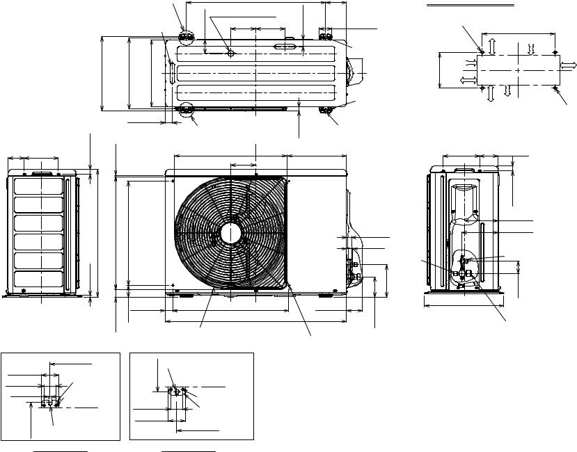
-RAV |
.1-2 |
|
UL-SP180AT2 |
Unit Outdoor |
.2 |
|
|
VIEWS) (EXTERNAL VIEWS CONSTRUCTION |
RAV-SP240AT2-UL
Note |
|
Ø0.9” (22) hole |
Name |
Refrigerant piping |
Conduit hole |
|
1 |
2 |
Drain hole |
(Ø1.0” (25) burring hole) |
B legs |
|
2.4” (60) |
|
15.0” (380) |
7.9” (200) |
Air inlet port |
(128) |
0”.5 |
.(175) |
7”.0 |
0.5” (12)
1”.2(54)
(48)9”.1
(170)7”.6 (34) 3”.1
(46)8”.1
3.0” (75)
inlet |
port |
Air |
|
(118)7”.4
(365)4”.14
Mounting bolt hole (Ø0.5” (12)×0.7” (17) U-shape hole) |
Details of B legs |
6”.1(40) |
||
Mounting bolt hole |
(Ø0.5” (12)×0.7” (17) long hole) |
Details of A legs |
6”.1(40) |
||
|
1.5” (39) |
3.8” (96) |
A legs |
2.8” (70) |
(600) |
Air outlet port |
15.1” (383) |
23.6” |
|
5.9” (150) |
|
9”.2(74) |
(88) |
|
7”.0.(175) |
||
5-drain hole Ø0.8” (20)×3.5” burring hole |
||
|
12.6” (320) |
|
|
1.2” (30) |
Refrigerant pipe connecting port Ø0.4” (9.5) flare at liquid side |
Refrigerant pipe connecting port |
35.4” (900) |
(550) |
|
21.7” |
|
2.0” (52) |
|
|
|
|
|
2.5” (64) |
|
|
|
|
1 |
7”.3(95) |
2”.2(55) |
(12) |
|
|
||
|
|
0.5” |
|
|
||||
0”.35(890) |
|
|
|
|
||||
|
|
|
|
|
||||
|
|
|
.10"(24) |
|
|
|
||
|
|
|
2.3” (58) |
|
15.7” (400) |
|
||
2 |
1 |
|
0.7” (18) |
3.9” (99) |
|
|
||
flare |
|
0”.2(50) |
4”.3(85) |
|
|
|
||
|
1”.5(130) |
2”.2(56) |
|
|
|
|||
(15.9)Ø0.6” sidegasat |
|
|
(7)0.3” |
|
||||
|
|
|
|
|
3”.0(7) |
|||
|
|
|
|
|
|
|
||
|
|
0”.10(255) |
|
|
|
|
||
|
|
7”.9(247) |
|
|
|
|
||
|
|
|
Z |
|
|
(83) |
|
|
|
|
|
|
|
|
3.3” |
|
|
|
|
|
|
7” (178) |
|
|
|
|
|
|
|
|
7” (178) 7” (178) |
20.4” (518) |
12.9” (327) |
|
|
0”.21(534) |
(165) |
(60) |
(68) |
|
|
|||
2.4” |
2.7” |
holeMounting separatelysold emboss)(3)Ø0.1”-(12 |
||||||
|
|
|
5”.6 |
|||||
|
|
|
|
|
|
|
||
9”.22(581) |
8”.5(148) |
|
|
|
|
|||
(65) 6”.2 viewsZ
forKnockout pipingdownward
– 13 –

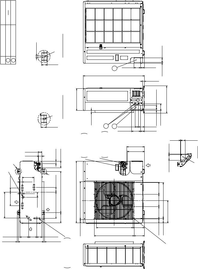
RAV-SP300AT2-UL, RAV-SP360AT2-UL, RAV-SP420AT2-UL
Note |
|
Ø0.9” (22) hole |
Name |
Refrigerant piping |
Conduit hole |
|
1 |
2 |
Drain hole |
(Ø1.0” (25) burring hole) |
B legs |
|
2.4” (60) |
|
15.0” (380) |
7.9” (200) |
Air inlet port |
0”.5(128) 7”.0.(175)
|
|
Mounting bolt hole (Ø0.5” (12)×0.7” (17) U-shape hole) |
Details of B legs |
|
|
|
|
|
(12) |
6”.1(40) |
|
|
|
|
|
|
|
0.5” |
|
|
|
|
|
|
||
|
Mounting bolt hole (Ø0.5” (12)×0.7” (17) long hole) |
|
|
|
|
|
|
|
|
|
Details of A legs |
(96)3.8” |
|
12.6” (320) |
pipeRefrigerant portconnecting flare(15.9)Ø0.6” sidegasat |
||
9”.1(48) |
6”.1(40) |
(39)1.5” |
|
|
pipeRefrigerant portconnecting flare(9.5)Ø0.4” sideliquidat |
|||
|
|
|
|
|
|
|
||
1”.2(54) |
|
|
|
|
|
|
|
|
7”.6(170) |
|
legs |
(70) |
|
|
|
|
|
3”.1(34) |
|
A |
15.1”(383) 2.8” |
23.6” (600) |
|
35.4” (900) 21.7”(550) |
|
|
3.0”(75) |
|
|
|
|||||
|
Airoutlet port |
(150) |
|
|||||
8”.1(46) |
|
|
|
|
|
|
|
|
inlet port |
|
|
|
|
5.9” |
|
(52) |
|
Air |
|
|
|
|
|
|
2.0” |
|
6”.4(118) |
9”.2(74) |
|
|
|
9”.22(581) |
|||
4”.14(365) |
7”.0.(175) |
5-drain hole Ø0.8” (20)×3.5” (88) |
0”.21(534) |
|||||
|
|
|
|
|
||||
|
|
|
|
|
burring hole |
|
||
1 |
7”.3(95) |
|
8”.52(1340)
1.2” (30) |
2 |
1 |
|
|
|
(50) |
0”.2 |
|
|
(130) |
1”.5 |
|
|
1”.24(613) |
|
|
|
8”.23(605) |
|
9”.2(74) |
|
8”.4(121) |
9”.22(581) |
|
|
|
0”.21(534) |
8”.25(655) |
2”.14(360) |
|
|
2.5” (64) |
|
|
(12) |
2”.2(55) |
0.5” |
|
|
||
0”.1(24) |
|
|
2.3” (58) |
|
15.7” (400) |
0.7”(18) |
3.9” (99) |
|
4”.3(85) |
|
|
(56)2”.2
(7)3”.0
|
|
0.3” (7) |
Z |
3.3” (83) |
|
|
|
|
7” (178) |
|
|
7” (178) 7” (178) |
20.4” (518) |
12.9” (327) |
2.4” (60) |
2.7” (68) |
|
|
7”.2(70) |
|
|
3”.3(85) |
|
|
Mounting hole |
sold separately (24-Ø0.1” (3) emboss) |
(65) 6”.2 viewsZ
forKnockout pipingdownward
– 14 –
3. SYSTEMATIC REFRIGERATING CYCLE DIAGRAM
3-1. Indoor Unit
• Single type (Combination of 1 indoor unit and 1 outdoor unit)
(Indoor unit)
Distributor
(Strainer incorporated)
TCJ sensor
Strainer
Air heat
exchanger TC sensor 


 Heating Cooling
Refrigerant pipe at liquid side (Outer dia : ØB)
Refrigerant pipe at gas side (Outer dia : ØA)
To outdoor unit |
To outdoor unit |
Dimension table
Indoor unit |
|
Outer diameter of refrigerant pipe |
|
|
|
|
|
|
Gas side ØA |
Liquid side ØB |
|
|
|
||
|
|
|
|
RAV-SP180AT2-UL |
1/2” (12.7) |
1/4” (6.4) |
|
|
|
|
|
RAV-SP240, 300, 360, 420AT2-UL |
5/8” (15.9) |
3/8” (9.5) |
|
|
|
|
|
– 15 –
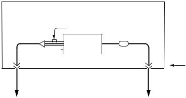
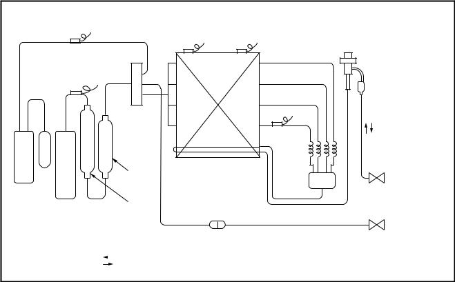
3-2. Outdoor Unit
RAV-SP180AT2-UL
|
|
TO sensor |
PMV |
|
|
|
(Pulse Motor Valve) |
||
|
|
|
||
|
|
|
(CAM-B30YGTF-2) |
|
TS |
TD |
|
|
|
sensor |
sensor |
|
|
|
|
|
|
TE sensor |
|
|
4-way valve |
|
|
Muffler |
|
|
|
Ø31.75 × 200L |
|
|
(STF-0213Z) |
|
|
|
|
|
|
|
|
|
Muffler |
Heat exchanger |
|
|
|
Ø19.05 × 160L |
|
|
|
|
Ø8 ripple, 2 rows, 20 stages |
|
|
|
|
|
|
|
|
|
|
FP1.3, flat fin |
Distributor |
Strainer |
|
|
|
||
Accumulator |
|
|
|
Refrigerant pipe |
(1L) |
|
|
|
|
Rotary compressor |
|
|
at liquid side Ø6.4 |
|
(DA150A1F-21F) |
Packed valve |
|
Refrigerant pipe |
||
|
||
|
at gas side Ø12.7 |
|
|
Packed valve |
|
|
2-step muffler |
|
|
Ø25 × 200L |
|
|
In cooling operation |
|
|
In heating operation |
|
|
|
Pressure |
|
Pipe surface temperature °F (°C) |
Compressor |
|
Indoor/Outdoor |
||||||
|
|
|
|
|
|
|
|
|
|
|
||||
|
|
(psi) |
(MPa) |
Discharge |
Suction |
Indoor heat |
Outdoor heat |
drive revolution |
Indoor |
temp. conditions |
||||
|
|
(DB/WB) °F °C) |
||||||||||||
|
|
exchanger |
exchanger |
frequency |
fan |
|||||||||
|
|
|
|
|
|
|
|
|
|
|||||
|
|
|
|
|
|
|
|
|
|
(rps) |
|
|
|
|
|
|
Pd |
Ps |
Pd |
Ps |
(TD) |
(TS) |
(TC) |
(TE) |
|
Indoor |
Outdoor |
||
|
|
|
|
|||||||||||
|
|
|
|
|
|
|
|
|
|
|
|
|
|
|
|
Standard |
416.2 |
145.0 |
2.87 |
1.00 |
161.6 |
60.8 |
55.4 |
107.6 |
58 |
HIGH |
80.6/66.2 |
95/– |
|
|
(72) |
(16) |
(13) |
(42) |
(27/19) |
(35/–) |
||||||||
|
|
|
|
|
|
|
|
|||||||
|
|
|
|
|
|
|
|
|
|
|
|
|
|
|
Cooling |
Overload |
517.7 |
159.5 |
3.57 |
1.10 |
190.4 |
68 |
66.2 |
125.6 |
65 |
HIGH |
89.6/75.2 |
109.4/– |
|
(88) |
(20) |
(19) |
(52) |
(32/24) |
(43/–) |
|||||||||
|
|
|
|
|
|
|
|
|||||||
|
|
|
|
|
|
|
|
|
|
|
|
|
|
|
|
Low load |
248.0 |
110.2 |
1.71 |
0.76 |
113.0 |
53.6 |
44.6 |
55.4 |
30 |
LOW |
64.4/59.9 |
23/– |
|
|
(45) |
(12) |
( 7) |
(13) |
(18/15.5) |
(–5/–) |
||||||||
|
|
|
|
|
|
|
|
|||||||
|
|
|
|
|
|
|
|
|
|
|
|
|
|
|
|
Standard |
327.7 |
98.6 |
2.26 |
0.68 |
150.8 |
42.8 |
98.6 |
37.4 |
64 |
HIGH |
68/– |
44.6/42.8 |
|
|
(66) |
( 6) |
(37) |
( 3) |
(20/–) |
(7/6) |
||||||||
|
|
|
|
|
|
|
|
|||||||
|
|
|
|
|
|
|
|
|
|
|
|
|
|
|
Heating |
Overload |
471.3 |
165.3 |
3.25 |
1.14 |
172.4 |
68.0 |
127.4 |
60.8 |
30 |
LOW |
86/– |
75.2/64.4 |
|
(78) |
(20) |
(53) |
(16) |
(30/–) |
(24/18) |
|||||||||
|
|
|
|
|
|
|
|
|||||||
|
|
|
|
|
|
|
|
|
|
|
|
|
|
|
|
Low load |
290.0 |
36.3 |
2.00 |
0.25 |
172.4 |
–0.4 |
93.2 |
–0.4 |
88 |
HIGH |
59/– |
5/– |
|
|
(78) |
(–18) |
(34) |
(–18) |
(15/–) |
(–15/–) |
||||||||
|
|
|
|
|
|
|
|
|||||||
|
|
|
|
|
|
|
|
|
|
|
|
|
|
|
– 16 –
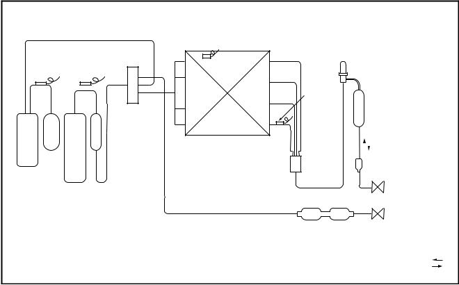
RAV-SP240AT2-UL
TS sensor |
|
|
PMV |
|
|
TO sensor |
TL sensor |
||
|
(Pulse Motor Valve) |
|||
|
|
|
(CAM-B30YGTF-2) |
|
|
|
|
Ø2 × Ø3 × 600L |
|
TD |
|
|
|
|
sensor |
|
|
Ø2 × Ø3 × 550L |
|
Accumulator |
|
|
Strainer |
|
Sub-ass’y |
|
|
Ø2 × Ø3 × 450L |
|
|
|
|
||
4-way valve |
|
|
TE sensor |
|
(STF-0218G) |
|
|
|
|
|
|
|
Ø2 × Ø3 |
|
|
|
|
× 450L |
|
Muffler |
|
|
Capillary |
|
|
|
|
||
|
Heat exchanger |
Refrigerant pipe |
||
Ø25 × L180 |
Ø8, 2 rows, 34 stages |
|||
at liquid side Ø9.5 |
||||
FP1.45, flat fin |
||||
|
Packed valve |
|||
Accumulator |
|
|
||
|
|
|
||
(1.8L) |
|
|
|
|
Rotary compressor Ø25 × L210 |
|
|
|
|
(DA220A2F-22L) |
|
|
Refrigerant pipe |
|
|
|
|
at gas side Ø15.9 |
|
|
|
Strainer |
Ball valve |
|
|
|
|
In cooling operation |
|
|
|
|
|
||
In heating operation |
|
||
|
|
|
Pressure |
|
|
Pipe surface temperature °F (°C) |
Compressor |
|
Indoor/Outdoor |
|||||
|
|
|
|
|
|
|
|
|
|
|
|
|||
|
|
(psi) |
(MPa) |
Discharge |
Suction |
Indoor heat |
Outdoor heat |
drive revolution |
Indoor |
temp. conditions |
||||
|
|
(DB/WB) °F °C) |
||||||||||||
|
|
|
|
|
exchanger |
exchanger |
frequency |
fan |
||||||
|
|
|
|
|
|
|
|
|
|
|
||||
|
|
|
|
|
|
|
|
|
|
|
(rps) |
|
|
|
|
|
Pd |
Ps |
Pd |
Ps |
(TD) |
|
(TS) |
(TC) |
(TE) |
|
Indoor |
Outdoor |
|
|
|
|
|
|
||||||||||
|
|
|
|
|
|
|
|
|
|
|
|
|
|
|
|
Standard |
404.6 |
129.1 |
2.79 |
0.89 |
158.0 |
|
55.4 |
51.8 |
102.2 |
58.2 |
HIGH |
80.6/66.2 |
95/– |
|
(70) |
|
(13) |
(11) |
(39) |
(27/19) |
(35/–) |
|||||||
|
|
|
|
|
|
|
|
|
||||||
|
|
|
|
|
|
|
|
|
|
|
|
|
|
|
Cooling |
Overload |
511.9 |
155.2 |
3.53 |
1.07 |
177.8 |
|
62.6 |
57.2 |
118.4 |
65.0 |
HIGH |
89.6/75.2 |
109.4/– |
(81) |
|
(17) |
(14) |
(48) |
(32/24) |
(43/–) |
||||||||
|
|
|
|
|
|
|
|
|
||||||
|
|
|
|
|
|
|
|
|
|
|
|
|
|
|
|
Low load |
248.0 |
104.4 |
1.71 |
0.72 |
107.6 |
|
44.6 |
37.4 |
64.4 |
30.0 |
LOW |
64.4/59.9 |
23/– |
|
(42) |
|
( 7) |
( 3) |
(18) |
(18/15.5) |
(–5/–) |
|||||||
|
|
|
|
|
|
|
|
|
||||||
|
|
|
|
|
|
|
|
|
|
|
|
|
|
|
|
Standard |
384.3 |
98.6 |
2.65 |
0.68 |
165.2 |
|
39.2 |
111.2 |
37.4 |
61.5 |
HIGH |
68 |
44.6/42.8 |
|
(74) |
|
( 4) |
(44) |
( 3) |
(20/–) |
(7/6) |
|||||||
|
|
|
|
|
|
|
|
|
||||||
|
|
|
|
|
|
|
|
|
|
|
|
|
|
|
Heating |
Overload |
464.0 |
161.0 |
3.2 |
1.11 |
168.8 |
|
66.2 |
125.6 |
59 |
28.0 |
LOW |
86/– |
75.2/64.4 |
(76) |
|
(19) |
(52) |
(15) |
(30/–) |
(24/18) |
||||||||
|
|
|
|
|
|
|
|
|
||||||
|
|
|
|
|
|
|
|
|
|
|
|
|
|
|
|
Low load |
337.9 |
30.5 |
2.33 |
0.21 |
199.4 |
|
–0.4 |
87.8 |
–4 |
99.6 |
HIGH |
59/– |
5/– |
|
(93) |
|
(–18) |
(31) |
(–20) |
(15/–) |
(–15/–) |
|||||||
|
|
|
|
|
|
|
|
|
||||||
|
|
|
|
|
|
|
|
|
|
|
|
|
|
|
– 17 –
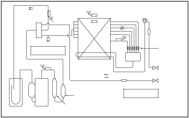
RAV-SP300AT2-UL, RAV-SP360AT2-UL, RAV-SP420AT2-UL
|
TS sensor |
TO sensor |
|
|
|
|
|
|
|
|
|
|
PMV |
|
|
|
TL sensor |
|
|
|
|
|
Strainer |
|
|
Check joint |
|
TE sensor |
Capillary |
|
Cooling: High pressure |
|
|
|
|
|
|
Ø4 ×Ø3 (6 pcs.) |
|
|
Heating: Low pressure |
|
|
|
|
|
|
|
|
|
|
Heat exchanger |
Distributor |
Refrigerant pipe |
|
TD sensor |
Ø8, 2 rows, 52 stages |
||
|
|
FP1.45, flat fin |
|
at liquid side Ø9.5 |
|
|
|
|
Packed valve |
|
|
In cooling operation |
|
|
|
|
In heating operation |
|
Refrigerant pipe |
|
|
|
Strainer |
at gas side Ø15.9 |
|
|
|
Ball valve |
|
|
Muffler |
|
Cooling: Low pressure |
|
|
|
Ø25 × L180 |
Heating: High pressure |
|
|
Ø25 × L210 |
|
|
|
Accumulator |
Rotary compressor |
|
|
|
(2500cc) |
(DA422A3F-25M) |
|
|
|
RAV-SP300AT2-UL
|
|
|
Pressure |
|
|
Pipe surface temperature °F (°C) |
|
Compressor |
|
Indoor/Outdoor |
|||||
|
|
(psi) |
(MPa) |
Discharge |
Suction |
Indoor heat |
Outdoor heat |
drive revolution |
Indoor |
temp. conditions |
|||||
|
|
exchanger |
exchanger |
frequency |
fan |
(DB/WB) °F (°C) |
|||||||||
|
|
Pd |
Ps |
Pd |
Ps |
(TD) |
|
(TS) |
(TC) |
(TL) |
(TE) |
(rps) |
|
Indoor |
Outdoor |
|
|
|
|
|
|||||||||||
|
Standard |
372.7 |
143.6 |
2.57 |
0.99 |
150.8 |
|
57.2 |
53.6 |
111.2 |
104.0 |
38 |
HIGH |
80.6/66.2 |
95/– |
|
(66) |
|
(14) |
(12) |
(44) |
(38) |
(27/19) |
(35/–) |
|||||||
|
|
|
|
|
|
|
|
|
|||||||
Cooling |
Overload |
478.5 |
158.1 |
3.30 |
1.09 |
172.4 |
|
48.2 |
55.4 |
120.2 |
109.4 |
53 |
HIGH |
89.6/75.2 |
109.4/– |
(78) |
|
( 9) |
(13) |
(49) |
(43) |
(32/24) |
(43/–) |
||||||||
|
|
|
|
|
|
|
|
|
|||||||
|
Low load |
252.3 |
108.8 |
1.74 |
0.75 |
114.8 |
|
44.6 |
41.0 |
89.6 |
77.0 |
21 |
LOW |
64.4/59.9 |
23/– |
|
(46) |
|
( 7) |
( 5) |
(32) |
(25) |
(18/15.5) |
(–5/–) |
|||||||
|
|
|
|
|
|
|
|
|
|||||||
|
Standard |
336.4 |
105.9 |
2.32 |
0.73 |
149.0 |
|
37.4 |
102.2 |
35.6 |
37.4 |
43 |
HIGH |
68/– |
44.6/42.8 |
|
(65) |
|
( 3) |
(39) |
( 2) |
( 3) |
(20/–) |
(7/6) |
|||||||
|
|
|
|
|
|
|
|
|
|||||||
Heating |
Overload |
466.9 |
169.7 |
3.22 |
1.17 |
163.4 |
|
66.2 |
129.2 |
57.2 |
59.0 |
26 |
LOW |
86/– |
75.2/64.4 |
(73) |
|
(19) |
(54) |
(14) |
(15) |
(30/–) |
(24/18) |
||||||||
|
|
|
|
|
|
|
|
|
|||||||
|
Low load |
314.7 |
43.5 |
2.17 |
0.30 |
188.6 |
|
5 |
100.4 |
6.8 |
8.6 |
71 |
HIGH |
59/– |
5/– |
|
(87) |
|
(–15) |
(38) |
(–14) |
(–13) |
(15/–) |
(–15/–) |
|||||||
|
|
|
|
|
|
|
|
|
|||||||
This compressor has 4-pole motor. The value when compressor frequency (Hz) is measured by a clamp meter becomes 2 times of No. of compressor revolutions (rps).
RAV-SP360AT2-UL, RAV-SP420AT2-UL
|
|
|
Pressure |
|
|
Pipe surface temperature °F (°C) |
|
Compressor |
|
Indoor/Outdoor |
|||||
|
|
(psi) |
(MPa) |
Discharge |
Suction |
Indoor heat |
Outdoor heat |
drive revolution |
Indoor |
temp. conditions |
|||||
|
|
exchanger |
exchanger |
frequency |
fan |
(DB/WB) °F (°C) |
|||||||||
|
|
Pd |
Ps |
Pd |
Ps |
(TD) |
|
(TS) |
(TC) |
(TL) |
(TE) |
(rps) |
|
Indoor |
Outdoor |
|
Standard |
394.4 |
130.5 |
2.72 |
0.90 |
163.4 |
|
53.6 |
50 |
114.8 |
100.4 |
51 |
HIGH |
80.6/66.2 |
95/– |
|
(73) |
|
(12) |
(10) |
(46) |
(38) |
(27/19) |
(35/–) |
|||||||
|
|
|
|
|
|
|
|
|
|||||||
Cooling |
Overload |
484.3 |
155.2 |
3.34 |
1.07 |
176.0 |
|
48.2 |
55.4 |
123.8 |
113.0 |
55 |
HIGH |
89.6/75.2 |
109.4/– |
(80) |
|
( 9) |
(13) |
(51) |
(45) |
(32/24) |
(43/–) |
||||||||
|
|
|
|
|
|
|
|
|
|||||||
|
Low load |
253.8 |
110.2 |
1.75 |
0.76 |
116.6 |
|
46.4 |
42.8 |
91.4 |
77.0 |
21 |
LOW |
64.4/59.9 |
23/– |
|
(47) |
|
( 8) |
( 6) |
(33) |
(25) |
(18/15.5) |
(–5/–) |
|||||||
|
|
|
|
|
|
|
|
|
|||||||
|
Standard |
375.6 |
100.1 |
2.59 |
0.69 |
167 |
|
37.4 |
109.4 |
35.6 |
35.6 |
53 |
HIGH |
68/– |
44.6/42.8 |
|
(45) |
|
( 3) |
(43) |
( 2) |
( 2) |
(20/–) |
(7/6) |
|||||||
|
|
|
|
|
|
|
|
|
|||||||
Heating |
Overload |
453.9 |
152.3 |
3.13 |
1.05 |
161.6 |
|
60.8 |
127.4 |
53.6 |
55.4 |
26 |
LOW |
86/– |
75.2/64.4 |
(72) |
|
(16) |
(53) |
(12) |
(13) |
(30/–) |
(24/18) |
||||||||
|
|
|
|
|
|
|
|
|
|||||||
|
Low load |
348.0 |
30.45 |
2.40 |
0.21 |
206.6 |
|
–7.6 |
107.6 |
–2.2 |
–0.4 |
90 |
HIGH |
59/– |
5/– |
|
(97) |
|
(–22) |
(42) |
(–19) |
(–18) |
(15/–) |
(–15/–) |
|||||||
|
|
|
|
|
|
|
|
|
|||||||
This compressor has 4-pole motor. The value when compressor frequency (Hz) is measured by a clamp meter becomes 2 times of No. of compressor revolutions (rps).
–18 –
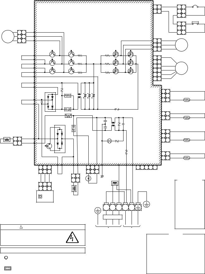
4. WIRING DIAGRAM
4-1. Outdoor Unit
RAV-SP180AT2-UL
|
|
|
|
|
|
|
|
|
|
ORN |
|
49C |
|
|
|
|
|
|
|
|
CN500 |
2 |
2 |
3 3 |
|||
|
|
|
|
|
|
|
1 |
1 |
BLK |
1 |
1 |
||
|
|
|
|
P.C. Board |
|
|
|
|
|
||||
|
|
|
|
|
|
|
|
|
|
HP SW |
|||
Compressor |
|
|
|
(MCC-5009) |
|
|
|
|
|
3 3 |
|||
1 1 RED |
P04 |
|
|
|
|
|
|
|
|
|
|||
|
|
|
|
|
|
|
|
1 1 |
|||||
CM |
2 2 |
WHI |
P05 |
|
|
CN300 |
|
|
BLK |
|
|
||
|
3 3 |
BLK |
P06 |
|
|
3 |
3 |
|
|
||||
|
|
|
|
Q200~205 |
Q300~305 |
|
2 |
2 |
WHI |
FM |
|||
|
|
|
|
IGBT |
|
MOS-FET |
|
1 |
1 |
RED |
|
|
|
|
|
P25 |
R221 |
|
R321 |
|
|
|
|
|
Fan motor |
||
YEL |
P24 |
R220 |
|
R320 |
|
6 |
6 |
|
|
|
|
||
|
|
P23 |
|
|
5 |
|
|
|
|
|
|||
YEL |
P22 |
R219 |
|
R319 |
|
4 |
4 |
|
|
PMV |
|||
|
|
P21 |
|
CN700 |
3 |
3 |
|
|
|||||
|
|
|
|
|
|
|
|||||||
BRN |
P20 |
|
|
|
|
2 |
2 |
|
|
Pulse |
|||
|
|
|
|
L03 |
C13 |
|
1 |
1 |
|
|
|||
|
|
P35 |
|
|
|
|
|
motor valve |
|||||
YEL |
P34 |
|
|
|
|
|
|
|
|
|
|
||
|
|
|
|
DB01 |
|
|
|
|
|
3 |
3 |
|
|
|
|
P19 |
|
|
|
CN603 |
|
2 |
|
|
|
||
|
|
|
|
F03 |
|
|
|
1 |
1 |
|
|
||
ORN |
P18 |
Power |
|
|
|
|
|
|
|||||
|
Fuse, T3.15A |
|
|
|
|
|
|
TS |
|||||
|
|
|
|
relay |
|
|
|
|
|
|
|
||
|
|
|
|
|
AC250V |
|
|
|
|
|
(Suction pipe temp. sensor) |
||
|
|
|
|
|
|
|
|
|
|
|
|||
|
|
|
|
C12 |
C14 |
|
|
|
2 |
2 |
|
|
|
|
|
|
|
|
|
Varistor |
CN602 |
|
|
|
|||
|
|
|
|
|
|
|
1 |
1 |
|
|
|||
|
|
|
|
CT |
|
|
|
|
|
|
TO |
||
|
|
|
|
|
|
|
|
|
|
|
|
||
|
|
|
|
DB02 |
|
L1 |
|
|
|
|
|
|
|
|
|
|
|
|
|
|
|
|
|
(Outdoor temp. sensor) |
|||
|
|
|
|
|
|
|
|
|
|
|
|||
|
|
|
|
Relay |
|
|
|
|
|
3 |
3 |
|
|
Reactor |
|
|
|
|
|
Surge |
|
|
|
|
|
||
|
|
|
|
|
CN601 |
|
2 |
|
|
|
|||
|
P11 |
|
|
absorber |
|
|
|
|
|||||
2 |
2 |
|
|
|
|
|
|
||||||
P08 |
|
|
|
|
|
|
1 |
1 |
|
|
|||
1 1 |
|
|
|
|
|
|
|
TD |
|||||
|
|
Varistor |
|
|
|
|
|
|
|||||
|
|
|
|
|
|
|
|
|
|
||||
|
|
|
|
|
|
|
|
|
|
|
|
(Discharge pipe temp. sensor) |
|
|
|
|
|
|
|
|
|
|
|
|
F01 |
|
|
|
|
|
|
|
|
|
|
|
|
|
|
Q404 |
|
|
|
|
|
|
Fuse, T25A |
|
|
|
|
CN600 |
2 |
2 |
|||||
|
|
|
|
|
|
|
|
|
|
|
AC250V |
|
|
|
|
|
||||||
|
|
|
|
P33 |
|
P32 |
|
CN701 |
|
P7 |
P03 |
P10 |
P02 |
|
CN806 |
|
|
1 |
1 |
|||
|
|
|
|
|
|
|
|
|
|
|
TE |
|||||||||||
|
|
1 |
2 |
3 |
|
|
|
|
1 |
3 |
|
|
|
|
1 |
2 |
3 |
4 |
5 |
|
|
(Condenser pipe temp. sensor) |
|
CN605 |
|
P31 |
|
P30 |
BLK |
ORN |
BLK |
WHI |
|
|
|
||||||||||
|
BLK |
1 2 3 |
PUR |
2 1 |
1 |
3 |
For optional |
|
|
|
|
|||||||||||
|
|
RED |
WHI |
BLK |
|
|
|
|
|
|
P.C. Board |
|
|
|
Color |
|||||||
|
|
|
|
2 |
1 |
|
|
|
|
|
|
|
|
|
|
|
|
|
||||
|
|
1 2 3 |
|
|
|
|
Reactor |
|
|
|
|
|
|
|
|
|
|
Identification |
||||
|
|
|
|
|
|
Coil for |
|
|
|
|
|
|
|
|
|
|
||||||
|
|
|
|
|
|
|
|
|
|
|
|
|
|
|
|
|
BLK : BLACK |
|||||
|
|
1 2 3 |
|
Reactor |
|
|
4-way valve |
|
|
|
GRN/YEL |
|
|
|
||||||||
|
|
|
|
|
|
|
|
|
|
|
BLU : BLUE |
|||||||||||
|
|
SW802 |
|
|
|
|
|
|
|
|
|
|
|
|
|
|
|
|
|
|||
|
|
|
|
|
|
|
|
WHI |
RED |
WHI |
|
|
|
|
|
|
|
RED : RED |
||||
|
|
|
|
|
|
|
|
|
|
|
|
|
|
|
|
|
|
|||||
|
|
MCC-1530 |
|
|
|
|
|
|
|
|
|
|
|
|
|
GRY : GRAY |
||||||
|
|
|
|
|
|
|
|
|
|
|
|
|
|
|
|
|
|
|
||||
|
|
|
|
|
|
|
|
|
|
|
|
|
|
|
|
|
|
|
PNK : PINK |
|||
|
Sub P.C. Board |
|
|
|
|
|
|
|
|
|
|
|
|
|
|
|
|
|
||||
|
|
|
|
|
|
|
L1 L2 |
S |
L1 |
L2 |
|
|
|
|
|
|
|
GRN : GREEN |
||||
|
|
|
|
|
|
|
|
|
|
|
|
|
|
|
|
|
|
|||||
|
|
|
|
|
|
|
|
|
|
|
|
|
|
|
|
|
|
WHI : WHITE |
||||
|
|
|
|
|
|
|
|
|
|
|
|
|
|
|
|
|
|
|
|
|
|
|
|
|
|
|
|
|
|
|
|
|
|
|
|
|
|
|
|
|
|
|
|
|
BRN : BROWN |
|
|
|
|
|
|
|
|
|
|
|
High voltage |
|
|
|
|
|
|
|
|
|
ORN : ORANGE |
|
|
|
|
|
|
|
|
|
|
|
|
|
|
|
|
|
|
|
|
|
|
|
YEL : YELLOW |
|
CAUTION : HIGH VOLTAGE |
|
|
|
|
|
|
|
|
|
|
|
|
|
|
|
PUR : PURPLE |
|||||
|
|
|
|
|
To indoor |
|
Power supply |
|
|
|
|
|
|
|
||||||||
|
The high voltage circuit is incorporated. |
|
|
|
|
|
|
|
|
|
|
|
|
|
|
|||||||
|
|
|
|
|
|
|
|
|
208/230-1-60 |
|
|
|
|
|
|
NOTE |
||||||
|
Be careful to do the check service, as the |
|
|
|
|
|
|
|
|
|
|
|
|
|
|
|
|
|||||
|
|
|
|
|
|
|
|
|
|
|
|
|
CM |
|
: Compressor |
|||||||
|
electric shock may be caused in case of |
|
|
|
|
|
|
|
|
|
|
|
|
|
|
|||||||
|
touching parts on the P.C. board by hand. |
|
|
|
|
|
|
|
|
|
|
|
|
PMV |
: Pulse Motor Valve |
|||||||
|
|
|
|
|
|
|
|
|
|
|
|
|
|
|
|
|
|
FM |
|
: Fan Motor |
||
|
|
|
|
|
|
|
|
|
|
|
|
|
|
|
|
|
|
TE |
|
: Heat Exchanger Temp. Sensor |
||
|
The 4-way valve coil is turned on while the cooling operation |
|
|
|
|
|
|
|
|
|
TD |
|
: Discharge Temp. Sensor |
|||||||||
|
|
|
|
|
|
|
|
|
|
|
|
|
|
|
|
|
|
TO |
|
: Outdoor Temp. Sensor |
||
1. |
indicates the terminal block. |
|
|
|
|
|
|
|
|
|
|
|
|
|
TS |
|
: Suction Temp. Sensor |
|||||
|
|
|
|
|
|
|
|
|
|
|
|
|
IGBT |
: Insulated Gate Bipolar Transistor |
||||||||
|
Alphanumeric characters in the cycle indicate the terminal No. |
|
|
|
|
|
|
|
||||||||||||||
|
|
|
|
|
|
|
|
DB |
|
: Rectifier |
||||||||||||
2. The two-dot chain line indicates the wiring procured locally. |
|
|
|
|
|
|
|
|
CT |
|
: Curreut Transformer |
|||||||||||
3. |
indicates the P.C. board. |
|
|
|
|
|
|
|
|
|
|
|
|
|
49C |
: Compressor Case Thermostat |
||||||
4. For the indoor unit circuit, refer to the wiring diagram of the indoor unit. |
|
|
|
|
|
|
HP SW : High pressure switch |
|||||||||||||||
|
|
|
|
|
|
|
|
|
|
|
||||||||||||
– 19 –
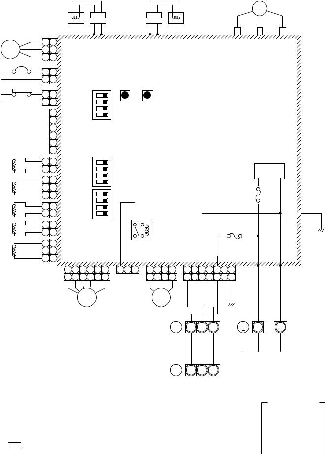
RAV-SP240AT2-UL
|
|
|
CM |
|
Reactor |
Reactor |
(RED) |
(WHI) |
(BLK) |
|
|
|||
|
|
|
(GRY) |
(GRY) |
(WHI) |
(WHI) |
U |
V |
W |
|
1 |
1 |
P04 P05 |
P06 P07 |
CN200 |
CN201 |
CN202 |
||
FM |
2 |
2 |
CN300 |
|
|
|
|
|
|
(WHI) |
|
|
|
|
|
|
|||
|
3 |
3 |
|
|
|
|
|
|
|
|
|
|
|
|
|
|
|
||
49C |
|
|
|
|
|
|
|
|
|
|
1 |
1 |
CN609 |
|
|
|
|
|
|
|
2 |
2 |
(BLU) |
|
|
|
|
|
|
HP |
SW |
|
SW804 SW801 SW800 |
|
|
|
|||
|
1 |
1 |
CN690 |
4 |
|
|
|
|
|
|
2 |
2 |
(RED) |
3 |
|
|
|
|
|
|
|
1 |
|
2 |
|
|
|
|
|
|
|
ON |
1 |
|
|
|
|
|
|
|
|
2 |
|
|
|
|
|
||
|
|
|
|
|
|
|
|
|
|
|
|
3 |
CN610 |
|
|
|
|
|
|
|
|
4 |
(YEL) |
|
Control P.C. Board |
|
|
|
|
|
|
5 |
SW803 |
|
|
|
|||
|
|
6 |
|
MCC-1571 |
|
|
|
||
|
|
|
|
|
|
|
|
|
|
TL |
1 |
1 |
CN604 |
|
2 |
2 |
(WHI) |
||
|
||||
|
1 |
1 |
CN603 |
|
TD |
|
2 |
||
|
(WHI) |
|||
|
3 |
3 |
||
|
|
|||
TO |
1 |
1 |
CN602 |
|
2 |
2 |
(YEL) |
||
|
||||
TE |
1 |
1 |
CN601 |
|
2 |
2 |
(WHI) |
||
|
|
4 |
|
3 |
|
2 |
ON |
1 |
|
4 |
|
3 |
|
2 |
ON |
1 |
SW802
L/F
Fuse, F01
T25A, 250V~
P09 
|
Fuse, F03 |
RY704 |
T10A, 250V~ |
(BLK)
1 |
1 |
CN600 |
|
|
|
TS |
2 |
CN701 |
CN04 |
||
(WHI) |
|||||
3 |
3 |
(WHI) |
(WHI) |
||
|
CN710 |
1 |
2 |
3 |
4 |
5 |
6 |
1 |
3 |
1 |
4 |
1 |
3 |
5 |
7 |
(WHI) |
1 |
2 |
3 |
4 |
|
6 |
CN704 |
1 |
4 |
1 |
3 |
5 |
7 |
|
|
|
|
|
|
|
|
(BLU) |
|
(GRY) |
|
(WHI) |
(RED) |
(BLK) |
|
|
|
|
PMW |
|
|
|
|
20SF |
|
|||||
|
|
|
|
|
|
|
|
|
Earth |
|
|
|
|
|
|
|
|
|
|
|
|
|
|
screw |
|
|
|
|
|
|
|
|
|
|
|
|
|
|
|
|
L1 |
L2 |
S |
|
|
|
|
|
|
|
|
|
|
|
|
|
|
|
|||
Symbol |
Parts name |
|
|
|
|
|
|
|
|
|
|
|
|
|
|
|
|
|
|
|
|
|
|
|
|
|
|
|
|||
CM |
Compressor |
|
|
|
|
|
|
|
|
|
|
|
|
|
|
FM |
Fan Motor |
|
Outdoor unit |
High voltage |
|
|
|||||||||
PMV |
Pulse Motor Valve |
|
|
|
|
|
|
||||||||
|
|
|
|
|
|||||||||||
TD |
Pipe temp. sensor (Discharge) |
|
|
|
|
|
|
|
|
|
|
|
|
|
|
Indoor unit |
|
|
|
|
|||||||||||
TS |
Pipe temp. sensor (Suction) |
|
|
|
|
|
|||||||||
|
S |
|
|
||||||||||||
TE |
Heat exchanger sensor 1 |
|
|
|
|
|
|
|
|
|
L1 |
L2 |
|
|
|
|
|
|
|
|
|
|
|
|
|||||||
|
|
|
|
|
|
|
|
|
|||||||
TL |
Heat exchanger sensor 2 |
|
Earth |
|
|
|
|
||||||||
|
|
|
|
||||||||||||
TO |
Outside temp. sensor |
|
screw |
|
|
|
|
||||||||
20SF |
4-way valve coil |
|
|
|
|
|
|
|
|
|
|
|
|
|
|
49C |
Compressor case thermostat |
|
|
|
|
|
|
|
|
|
|
|
|
|
|
|
|
|
|
|
|
|
|
|
|
|
|
|
|||
HP SW |
High pressure switch |
|
|
|
|
|
|
|
|
|
|
|
|
|
|
RY |
Relay |
|
|
|
|
|
|
|
|
|
|
|
|
|
|
L/F |
Line Filter |
|
|
|
|
|
|
|
|
|
|
|
|
|
|
1. indicates the terminal block.
Alphanumeric characters in the cycle indicate the terminal No.
2.The two-dot chain line indicates the wiring procured locally.
3.


 indicates the P.C. board.
4.For the indoor unit circuit, refer to the wiring diagram of the indoor unit.
P01 P02
(RED) (WHI)
Earth screw
L1  L2
L2
Power supply 208/230-1-60
Color
Identification
BLK : BLACK
BLU : BLUE
RED : RED
GRY : GRAY
WHI : WHITE
YEL : YELLOW
– 20 –
RAV-SP300AT2-UL, RAV-SP360AT2-UL, RAV-SP420AT2-UL
FM01 |
FM02 |
49C
HP SW
TL
TD
TO
TE
CM
Reactor (RED) (WHI) (BLK)
Reactor |
(GRY) |
(GRY) |
(WHI) |
(WHI) |
U |
V |
W |
||
|
|
|
|||||||
1 |
1 |
|
P04 P05 |
P06 P07 |
CN200 |
CN201 |
CN202 |
||
2 |
2 |
CN400 |
|
|
|
|
|
|
|
(WHI) |
|
|
|
|
|
|
|||
3 |
3 |
|
|
|
|
|
|
||
|
|
|
|
|
|
|
|
||
1 |
1 |
CN300 |
|
|
|
|
|
|
|
2 |
2 |
|
|
|
|
|
|
||
(WHI) |
|
|
|
|
|
|
|||
3 |
3 |
|
|
|
|
|
|
||
|
|
|
|
|
|
|
|
||
1 |
1 |
CN609 |
|
|
|
|
|
|
|
2 |
2 |
(BLU) |
|
|
|
|
|
|
|
|
|
|
SW804 SW801 SW800 |
|
|
|
|||
1 |
1 |
CN690 |
4 |
|
|
|
|
|
|
2 |
2 |
(RED) |
3 |
|
|
|
|
|
|
|
1 |
|
|
2 |
|
|
|
|
|
|
|
ON |
1 |
|
|
|
|
|
|
|
2 |
|
|
|
|
|
|
||
|
|
|
|
|
|
|
|
|
|
|
3 |
CN610 |
|
|
|
|
|
|
|
|
4 |
(YEL) |
|
Control P.C. Board |
|
|
|
||
|
5 |
|
SW803 |
|
|
|
|||
|
6 |
|
|
MCC-1570 |
|
|
|
||
|
|
|
|
|
|
|
|
|
|
11  CN604
CN604
22  (WHI)
(WHI)
1 |
1 |
CN603 |
|
|
2 |
||
|
(WHI) |
||
3 |
3 |
||
|
11  CN602
CN602
22  (YEL)
(YEL)
|
4 |
|
3 |
|
2 |
ON |
1 |
|
4 |
|
3 |
|
2 |
ON |
1 |
L/F
Fuse, F01
T25A, 250V~
P09 
1 |
1 |
CN601 |
SW802 |
|
Fuse, F03 |
|
RY704 |
T10A, 250V~ |
|||
2 |
2 |
(WHI) |
|
(BLK)
1 |
1 |
CN600 |
|
|
|
|
|
|
|
|
|
|
|
|
|
TS |
2 |
|
|
CN704 |
|
|
CN701 |
|
CN04 |
|
|
|
|||
(WHI) |
|
|
|
|
|
|
|
|
|||||||
3 |
3 |
|
|
|
(BLU) |
|
|
(WHI) |
|
(WHI) |
|
|
|
||
|
|
|
|
|
|
|
|
|
|
|
|||||
CN710 |
1 |
2 |
3 |
4 |
5 |
6 |
1 |
3 |
1 |
4 |
1 |
3 |
5 |
7 |
|
(WHI) |
1 |
2 |
3 |
4 |
|
6 |
|
|
1 |
4 |
1 |
3 |
5 |
7 |
|
PMW |
20SF |
(GRY) |
(WHI) |
(RED) |
(BLK) |
|
|
|
|
Symbol |
Parts name |
|
Earth |
|
|
|
|
||||||
CM |
Compressor |
|
screw |
|
|
|
|
||||||
FM01, 02 |
Fan Motor |
|
|
|
|
|
|
|
L1 |
L2 |
S |
|
|
|
|
|
|
|
|
|
|
||||||
PMV |
Pulse Motor Valve |
|
|
|
|
|
|
|
|
|
|||
|
|
|
|
|
|
|
|
|
|
|
|
||
|
|
|
|
|
|
|
|
|
|
|
|||
TD |
Pipe temp. sensor (Discharge) |
|
|
|
|
|
|
|
|
|
|
|
|
TS |
Pipe temp. sensor (Suction) |
|
|
|
|
|
|
|
High voltage |
|
|
||
TE |
Heat exchanger sensor 1 |
|
Outdoor unit |
|
|
|
|
|
|||||
|
|
|
|
|
|
||||||||
TL |
Heat exchanger sensor 2 |
|
|
|
|
|
|||||||
|
|
|
|
|
|
|
|
|
|
|
|
||
TO |
Outside temp. sensor |
|
Indoor unit |
|
|
|
|
||||||
|
|
|
|
||||||||||
20SF |
4-way valve coil |
|
|
S |
|
|
|||||||
|
|
|
|
|
|
|
L1 |
L2 |
|
|
|||
|
|
|
|
|
|
|
|
|
|
|
|||
49C |
Compressor case thermostat |
|
Earth |
|
|
|
|
||||||
|
|
|
|
||||||||||
HP SW |
High pressure switch |
|
|
|
|
|
|||||||
|
|
|
screw |
|
|
|
|
||||||
RY |
Relay |
|
|
|
|
|
|||||||
|
|
|
|
|
|
|
|
|
|
|
|
||
L/F |
Line Filter |
|
|
|
|
|
|
|
|
|
|
|
|
1. indicates the terminal block.
Alphanumeric characters in the cycle indicate the terminal No.
2.The two-dot chain line indicates the wiring procured locally.
3.


 indicates the P.C. board.
4.For the indoor unit circuit, refer to the wiring diagram of the indoor unit.
P01 P02
(RED) (WHI)
Earth screw
L1  L2
L2
Power supply 208/230-1-60
Color
Identification
BLK : BLACK
BLU : BLUE
RED : RED
GRY : GRAY
WHI : WHITE
YEL : YELLOW
– 21 –
5. SPECIFICATIONS OF ELECTRICAL PARTS
5-1. Outdoor Unit (Parts Ratings)
RAV-SP180AT2-UL
No. |
Parts name |
Type |
Specifications |
|
|
1 |
Fan motor |
ICF-140-43-4R |
Output (Rated) 43 W |
|
|
2 |
Compressor |
DA150A1F-21F |
3 phase, 4P, 1100 W |
|
|
3 |
Reactor |
CH-57 |
10mH, 16A |
|
|
4 |
Outdoor temp. sensor (To sensor) |
— |
10 kΩ at 77°F (25°C) |
|
|
5 |
Heat exchanger sensor (Te sensor) |
— |
10 kΩ at 77°F (25°C) |
|
|
6 |
Suction temp. sensor (Ts sensor) |
— |
10 kΩ at 77°F (25°C) |
|
|
7 |
Discharge temp. sensor (Td sensor) |
— |
50 kΩ at 77°F (25°C) |
|
|
8 |
Fuse (Switching power (Protect)) |
— |
T3.15 A, AC 250 V |
|
|
9 |
Fuse (Inverter, input (Current protect)) |
— |
AC 240 V, 25 A |
|
|
10 |
4-way valve solenoid coil |
STF-01AJ502E1 |
— |
|
|
11 |
Compressor thermo. (Protection) |
US-622 |
OFF : 257 ± 39.2°F (125 ± 4°C), |
|
|
ON : 194 ± 41°F (90 ± 5°C) |
|
||||
|
|
|
|
||
12 |
Coil (Pulse Motor Valve) |
CAM-MD12TF-12 |
— |
|
|
|
|
|
OFF : 601.8 + 0 |
|
|
13 |
Pressure switch |
ACB-4UB82W |
– 29 psi 4.15 + 0 |
|
|
4.15 – 0.2 MPa |
|||||
|
|
|
|||
|
|
|
ON : 464 ± 26 psi (3.2 ± 0.2 MPa) |
|
|
|
|
|
|
|
|
RAV-SP240AT2-UL
No. |
Parts name |
Type |
Specifications |
|
1 |
Compressor |
DA220A2F-22L |
— |
|
2 |
Outdoor fan motor |
ICF-280-A60-1 |
Output 60 W |
|
3 |
Reactor |
CH-56 |
5.8 mH, 18.5 A |
|
4 |
4-way valve coil |
VHV-01AP552B1 |
AC200 – 240 V |
|
5 |
PMV coil |
CAM-MD12TF-15 |
DC12 V |
|
6 |
P.C. board |
MCC-1571 |
AC208 / 230 V |
|
7 |
Fuse (Mounted on P.C. board) |
— |
AC250 V, 25 A |
|
8 |
Fuse (Mounted on P.C. board) |
— |
AC250 V, 10 A |
|
9 |
Fuse (Mounted on P.C. board) |
— |
AC250 V, 3.15 A |
|
10 |
Outdoor temp. sensor (TO sensor) |
— |
10 kΩ at 77°F (25°C) |
|
11 |
Heat exchanger sensor (Te sensor) |
— |
10 kΩ at 77°F (25°C) |
|
12 |
Discharge temp. sensor (Td sensor) |
— |
50 kΩ at 77°F (25°C) |
|
13 |
Heat exchanger Temp sensor (Ts sensor) |
— |
10 kΩ at 77°F (25°C) |
|
14 |
Compressor thermo. (Protection) |
US-622 |
OFF : 257 ± 39.2°F (125 ± 4°C), |
|
ON : 194 ± 41°F (90 ± 5°C) |
||||
|
|
|
||
|
|
|
OFF : 601.8 + 0 |
|
15 |
Pressure switch |
ACB-4UB82W |
601.8 – 29 psi 4.15 + 0.2 MPa |
|
601.8 – 29 psi 4.15 – 0.2 MPa |
||||
|
|
|
||
|
|
|
ON : 464 ± 26 psi (3.2 ± 0.2 MPa) |
|
|
|
|
|
|
|
|
|
|
RAV-SP300AT2-UL, RAV-SP360AT2-UL, RAV-SP420AT2-UL
No. |
Parts name |
Type |
Specifications |
|
1 |
Compressor |
DA422A3F-25M |
— |
|
2 |
Outdoor fan motor |
ICF-280-A100-1 |
Output 100W |
|
3 |
Reactor |
CH-62 |
5.7mH, 18.5A |
|
4 |
4-way valve coil |
VHV-01AP552B1 |
AC240V |
|
5 |
PMV coil |
UKV-A038 |
DC12V |
|
6 |
P.C. board |
MCC-1571 |
AC208 / 230 V |
|
7 |
Fuse (Mounted on P.C. board) |
— |
AC250V, 25A |
|
8 |
Fuse (Mounted on P.C. board) |
— |
AC250V, 10A |
|
9 |
Fuse (Mounted on P.C. board) |
— |
AC250V, 3.15A |
|
10 |
Outdoor temp. sensor (TO sensor) |
— |
10 kΩ at 77°F (25°C) |
|
11 |
Heat exchanger sensor (Te sensor) |
— |
10 kΩ at 77°F (25°C) |
|
12 |
Discharge temp. sensor (Td sensor) |
— |
50 kΩ at 77°F (25°C) |
|
13 |
Heat exchanger mid. Temp sensor (TL sensor) |
— |
10 kΩ at 77°F (25°C) |
|
14 |
Compressor thermo. (Protection) |
US-622 |
OFF : 257 ± 39.2°F (125 ± 4°C), |
|
ON : 194 ± 41°F (90 ± 5°C) |
||||
|
|
|
||
|
|
|
OFF : 601.8 + 0 |
|
15 |
Pressure switch |
ACB-4UB82W |
601.8 – 29 psi 4.15 + 0.2 MPa |
|
601.8 – 29 psi 4.15 – 0.2 MPa |
||||
|
|
|
||
|
|
|
ON : 464 ± 26 psi (3.2 ± 0.2 MPa) |
|
|
|
|
|
– 22 –
6. REFRIGERANT R410A
This air conditioner adopts the new refrigerant HFC (R410A) which does not damage the ozone layer.
The working pressure of the new refrigerant R410A is 1.6 times higher than conventional refrigerant (R22). The refrigerating oil is also changed in accordance with change of refrigerant, so be careful that water, dust, and existing refrigerant or refrigerating oil are not entered in the refrigerant cycle of the air conditioner using the new refrigerant during installation work or servicing time.
The next section describes the precautions for air conditioner using the new refrigerant.
Conforming to contents of the next section together with the general cautions included in this manual, perform the correct and safe work.
6-1. Safety During Installation/Servicing
As R410A’s pressure is about 1.6 times higher than that of R22, improper installation/servicing may cause a serious trouble. By using tools and materials exclusive for R410A, it is necessary to carry out installation/servicing safely while taking the following precautions into consideration.
1.Never use refrigerant other than R410A in an air conditioner which is designed to operate with R410A.
If other refrigerant than R410A is mixed, pressure in the refrigeration cycle becomes abnormally high, and it may cause personal injury, etc. by a rupture.
2.Confirm the used refrigerant name, and use tools and materials exclusive for the refrigerant R410A.
The refrigerant name R410A is indicated on the visible place of the outdoor unit of the air conditioner using R410A as refrigerant.
To prevent mischarging, the diameter of the service port differs from that of R22.
3.If a refrigeration gas leakage occurs during installation/servicing, be sure to ventilate fully.
If the refrigerant gas comes into contact with fire, a poisonous gas may occur.
4.When installing or removing an air conditioner, do not allow air or moisture to remain in the refrigeration cycle.
Otherwise, pressure in the refrigeration cycle may become abnormally high so that a rupture or personal injury may be caused.
5.After completion of installation work, check to make sure that there is no refrigeration gas leakage.
If the refrigerant gas leaks into the room, coming into contact with fire in the fan-driven heater, space heater, etc., a poisonous gas may occur.
6.When an air conditioning system charged with a large volume of refrigerant is installed in a small room, it is necessary to exercise care so that, even when refrigerant leaks, its concentration does not exceed the marginal level.
If the refrigerant gas leakage occurs and its concentration exceeds the marginal level, an oxygen starvation accident may result.
7.Be sure to carry out installation or removal according to the installation manual.
Improper installation may cause refrigeration trouble, water leakage, electric shock, fire, etc.
8.Unauthorized modifications to the air conditioner may be dangerous. If a breakdown occurs please call a qualified air conditioner technician or electrician.
Improper repair may result in water leakage, electric shock and fire, etc.
6-2. Refrigerant Piping Installation
6-2-1. Piping Materials and Joints Used
For the refrigerant piping installation, copper pipes and joints are mainly used.
Copper pipes and joints suitable for the refrigerant must be chosen and installed.
Furthermore, it is necessary to use clean copper pipes and joints whose interior surfaces are less affected by contaminants.
1.Copper Pipes
It is necessary to use seamless copper pipes which are made of either copper or copper alloy and it is desirable that the amount of residual oil is less than 0.0001 lbs / 32’ 10” (40 mg/10 m).
Do not use copper pipes having a collapsed, deformed or discolored portion (especially on the interior surface).
Otherwise, the expansion valve or capillary tube may become blocked with contaminants.
As an air conditioner using R410A incurs pressure higher than when using R22, it is necessary to choose adequate materials.
Thicknesses of copper pipes used with R410A are as shown in Table 6-2-1. Never use copper pipes thinner than 0.03” (0.8 mm) even when it is available on the market.
– 23 –
Table 6-2-1 Thicknesses of annealed copper pipes
|
|
Thickness (In (mm)) |
|
Outer diameter (In (mm)) |
R410A |
R22 |
|
1/4” |
(6.4) |
0.03” (0.80) |
0.03” (0.80) |
3/8” |
(9.5) |
0.03” (0.80) |
0.03” (0.80) |
1/2” (12.7) |
0.03” (0.80) |
0.03” (0.80) |
|
5/8” (15.9) |
0.04” (1.00) |
0.04” (1.00) |
|
1.Joints
For copper pipes, flare joints or socket joints are used. Prior to use, be sure to remove all contaminants.
a)Flare Joints
Flare joints used to connect the copper pipes cannot be used for pipings whose outer diameter exceeds 20 mm. In such a case, socket joints can be used.
Sizes of flare pipe ends, flare joint ends and flare nuts are as shown in Tables 6-2-3 to 6-2-5 below.
b)Socket Joints
Socket joints are such that they are brazed for connections, and used mainly for thick pipings whose diameter is larger than 0.79” (20 mm). Thicknesses of socket joints are as shown in Table 6-2-2.
Table 6-2-2 Minimum thicknesses of socket joints
Reference outer diameter of copper pipe jointed |
Minimum joint thickness |
|
(In (mm)) |
(In (mm)) |
|
|
|
|
1/4” |
(6.4) |
0.02” (0.50) |
|
|
|
3/8” |
(9.5) |
0.02” (0.60) |
|
|
|
1/2” (12.7) |
0.03” (0.70) |
|
|
|
|
5/8” (15.9) |
0.03” (0.80) |
|
|
|
|
6-2-2. Processing of Piping Materials
When performing the refrigerant piping installation, care should be taken to ensure that water or dust does not enter the pipe interior, that no other oil other than lubricating oils used in the installed air conditioner is used, and that refrigerant does not leak.
When using lubricating oils in the piping processing, use such lubricating oils whose water content has been removed. When stored, be sure to seal the container with an airtight cap or any other cover.
1.Flare Processing Procedures and Precautions
a)Cutting the Pipe
By means of a pipe cutter, slowly cut the pipe so that it is not deformed.
b)Removing Burrs and Chips
If the flared section has chips or burrs, refrigerant leakage may occur. Carefully remove all burrs and clean the cut surface before installation.
– 24 –
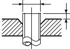
c)Insertion of Flare Nut
d)Flare Processing
Make certain that a clamp bar and copper pipe have been cleaned. By means of the clamp bar, perform the flare processing correctly. Use either a flare tool for R410A or conventional flare tool.
Flare processing dimensions differ according to the type of flare tool.
When using a conventional flare tool, be sure to secure “dimension A” by using a gauge for size adjustment.
ØD |
A |
|
|
|
|
|
Fig. 6-2-1 Flare processing dimensions |
|
|
|
Table 6-2-3 |
Dimensions related to flare processing for R410A / R22 |
|||
|
|
|
|
|
|
|
|
|
|
|
|
A (In (mm)) |
|
Outer diameter |
Thickness |
|
|
|
|
|
|
Flare tool for |
Conventional flare tool (R410A) |
||||
(In (mm)) |
(In (mm)) |
|
||||
|
|
|
||||
|
|
|
|
R410A, R22clutch type |
Clutch type |
Wing nut type |
|
|
|
|
|
||
|
|
|
|
|
|
|
1/4” |
(6.4) |
0.03” (0.8) |
|
0 – 0.02” (0 – 0.5) |
0.04” – 0.06” (1.0 – 1.5) |
0.06” – 0.08” (1.5 – 2.0) |
|
|
|
|
|
|
|
3/8” |
(9.5) |
0.03” (0.8) |
|
0 – 0.02” (0 – 0.5) |
0.04” – 0.06” (1.0 – 1.5) |
0.06” – 0.08” (1.5 – 2.0) |
|
|
|
|
|
|
|
1/2” (12.7) |
0.03” (0.8) |
|
0 – 0.02” (0 – 0.5) |
0.04” – 0.06” (1.0 – 1.5) |
0.08” – 0.10” (2.0 – 2.5) |
|
|
|
|
|
|
|
|
5/8” (15.9) |
0.04” (1.0) |
|
0 – 0.02” (0 – 0.5) |
0.04” – 0.06” (1.0 – 1.5) |
0.08” – 0.10” (2.0 – 2.5) |
|
|
|
|
|
|
|
|
Table 6-2-4 Flare and flare nut dimensions for R410A
Outer diameter |
Thickness |
|
|
|
Dimension (In (mm)) |
|
Flare nut width |
|||
|
|
|
|
|
|
|
||||
(In (mm)) |
(In (mm)) |
A |
|
B |
C |
|
D |
(In (mm)) |
||
|
|
|
|
|
|
|||||
|
|
|
|
|
|
|
|
|
|
|
1/4” |
(6.4) |
0.03” (0.8) |
0.36” |
(9.1) |
0.36” |
(9.2) |
0.26” |
(6.5) |
0.51” (13) |
0.67” (17) |
|
|
|
|
|
|
|
|
|
||
3/8” |
(9.5) |
0.03” (0.8) |
0.52” (13.2) |
0.53” (13.5) |
0.38” |
(9.7) |
0.79” (20) |
0.87” (22) |
||
|
|
|
|
|
|
|
||||
1/2” (12.7) |
0.03” (0.8) |
0.65” (16.6) |
0.63” (16.0) |
0.51” (12.9) |
0.91” (23) |
1.02” (26) |
||||
|
|
|
|
|
|
|
||||
5/8” (15.9) |
0.04” (1.0) |
0.78” (19.7) |
0.75” (19.0) |
0.63” (16.0) |
0.98” (25) |
1.14” (29) |
||||
|
|
|
|
|
|
|
|
|
|
|
|
|
Table 6-2-5 |
Flare and flare nut dimensions for R22 |
|
||||||
|
|
|
|
|
|
|
|
|
|
|
Outer diameter |
Thickness |
|
|
|
Dimension (In (mm)) |
|
Flare nut width |
|||
|
|
|
|
|
|
|
||||
(In (mm)) |
(In (mm)) |
A |
B |
C |
|
D |
(In (mm)) |
|||
|
|
|
|
|
||||||
|
|
|
|
|
|
|
|
|
|
|
1/4” |
(6.4) |
0.03” (0.8) |
0.36” |
(9.1) |
0.36” |
(9.2) |
0.26” |
(6.5) |
0.51” (13) |
0.67” (17) |
|
|
|
|
|
|
|
|
|
||
3/8” |
(9.5) |
0.03” (0.8) |
0.51” (13.0) |
0.53” (13.5) |
0.38” |
(9.7) |
0.79” (20) |
0.87” (22) |
||
|
|
|
|
|
|
|
||||
1/2” (12.7) |
0.03” (0.8) |
0.64” (16.2) |
0.63” (16.0) |
0.51” (12.9) |
0.79” (20) |
0.94” (24) |
||||
|
|
|
|
|
|
|
||||
5/8” (15.9) |
0.04” (1.0) |
0.76” (19.4) |
0.75” (19.0) |
0.63” (16.0) |
0.91” (23) |
1.06” (27) |
||||
|
|
|
|
|
|
|
||||
3/4” (19.0) |
0.04” (1.0) |
0.92” (23.3) |
0.94” (24.0) |
0.76” (19.2) |
1.34” (34) |
1.42” (36) |
||||
|
|
|
|
|
|
|
|
|
|
|
– 25 –
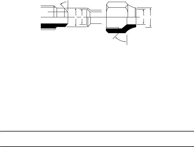
46˚ 45˚to 
B A |
C D |
43˚to |
45˚ |
|
Fig. 6-2-2 Relations between flare nut and flare seal surface
2.Flare Connecting Procedures and Precautions
a)Make sure that the flare and union portions do not have any scar or dust, etc.
b)Correctly align the processed flare surface with the union axis.
c)Tighten the flare with designated torque by means of a torque wrench. The tightening torque for R410A is the same as that for conventional R22. Incidentally, when the torque is weak, the gas leakage may occur.
When it is strong, the flare nut may crack and may be made non-removable.
When choosing the tightening torque, comply with values designated by manufacturers. Table 6-2-6 shows reference values.
NOTE
When applying oil to the flare surface, be sure to use oil designated by the manufacturer.
If any other oil is used, the lubricating oils may deteriorate and cause the compressor to burn out.
Table 6-2-6 Tightening torque of flare for R410A [Reference values]
Outer diameter (In (mm)) |
Tightening torque (ft • lbs (N • m)) |
|
|
|
|
1/4” |
(6.4) |
10 – 13 (14 – 18) |
|
|
|
3/8” |
(9.5) |
24 – 31 (33 – 42) |
|
|
|
1/2” (12.7) |
37 – 46 (50 – 62) |
|
|
|
|
5/8” (15.9) |
50 – 60 (68 – 82) |
|
|
|
|
– 26 –
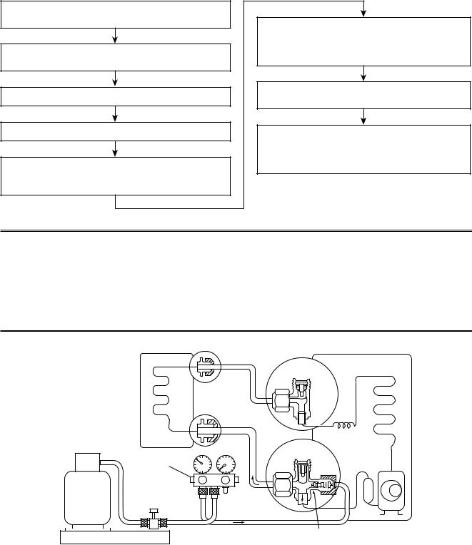
6-3. Tools
6-3-1. Required Tools
Refer to the “4.Tools” (Page 8)
6-4. Recharging of Refrigerant
When it is necessary to recharge refrigerant, charge the specified amount of new refrigerant according to the following steps.
Recover the refrigerant, and check no refrigerant remains in the equipment.
Connect the charge hose to packed valve service port at the outdoor unit’s gas side.
Connect the charge hose of the vacuum pump adapter.
Open fully both packed valves at liquid and gas sides.
Place the handle of the gauge manifold Low in the fully opened position, and turn on the vacuum pump’s power switch. Then, evacuating the refrigerant in the cycle.
When the compound gauge’s pointer has indicated –101 kpa (–76 cmHg), place the handle Low in the fully closed position, and turn off the vacuum pump’s power switch.
Keep the status as it is for 1 to 2 minutes, and ensure that the compound gauge’s pointer does not return.
Set the refrigerant cylinder to the electronic balance, connect the connecting hose to the cylinder and the connecting port of the electronic balance, and charge liquid refrigerant.
(For refrigerant charging, see the figure below.)
1)Never charge refrigerant exceeding the specified amount.
2)If the specified amount of refrigerant cannot be charged, charge refrigerant bit by bit in COOL mode.
3)Do not carry out additional charging.
When additional charging is carried out if refrigerant leaks, the refrigerant composition changes in the refrigeration cycle, that is characteristics of the air conditioner changes, refrigerant exceeding the specified amount is charged, and working pressure in the refrigeration cycle becomes abnormally high pressure, and may cause a rupture or personal injury.
(INDOOR unit) |
(Liquid side) |
(OUTDOOR unit) |
Opened
(Gas side)
Refrigerant cylinder (With siphon pipe)
Check valve
Closed
Open/Close valve for charging
Service port
Electronic balance for refrigerant charging
Fig. 6-4-1 Configuration of refrigerant charging
– 27 –
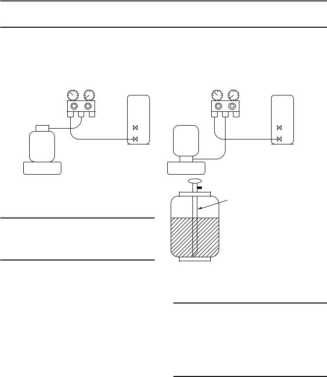
1)Be sure to make setting so that liquid can be charged.
2)When using a cylinder equipped with a siphon, liquid can be charged without turning it upside down.
It is necessary for charging refrigerant under condition of liquid because R410A is mixed type of refrigerant.
Accordingly, when charging refrigerant from the refrigerant cylinder to the equipment, charge it turning the cylinder upside down if cylinder is not equipped with siphon.
[ Cylinder with siphon ] |
[ Cylinder without siphon ] |
Gauge manifold |
Gauge manifold |
OUTDOOR unit |
OUTDOOR unit |
Refrigerant
cylinder
Electronic
balance
cylinder Refrigerant
Electronic
balance
Siphon
R410A refrigerant is HFC mixed refrigerant.
Therefore, if it is charged with gas, the composition of the charged refrigerant changes and the characteristics of the equipment varies.
Fig. 6-4-2
6-5. Brazing of Pipes
6-5-1. Materials for Brazing
1.Silver brazing filler
Silver brazing filler is an alloy mainly composed of silver and copper.
It is used to join iron, copper or copper alloy, and is relatively expensive though it excels in solderability.
1)Phosphor bronze brazing filler tends to react with sulfur and produce a fragile compound water solution, which may cause a gas leakage. Therefore, use any other type of brazing filler at a hot spring resort, etc., and coat the surface with a paint.
2)When performing brazing again at time of servicing, use the same type of brazing filler.
2.Phosphor bronze brazing filler
Phosphor bronze brazing filler is generally used to join copper or copper alloy.
3.Low temperature brazing filler
Low temperature brazing filler is generally called solder, and is an alloy of tin and lead.
Since it is weak in adhesive strength, do not use it for refrigerant pipes.
6-5-2. Flux
1.Reason why flux is necessary
•By removing the oxide film and any foreign matter on the metal surface, it assists the flow of brazing filler.
•In the brazing process, it prevents the metal surface from being oxidized.
•By reducing the brazing filler's surface tension, the brazing filler adheres better to the treated metal.
– 28 –
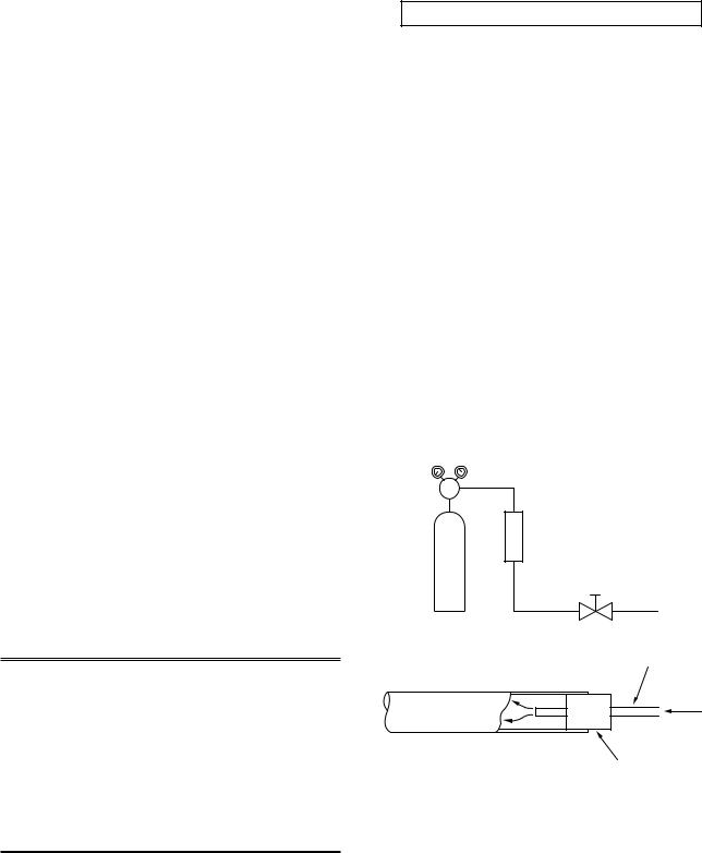
2.Characteristics required for flux
•Activated temperature of flux coincides with the brazing temperature.
•Due to a wide effective temperature range, flux is hard to carbonize.
•It is easy to remove slag after brazing.
•The corrosive action to the treated metal and brazing filler is minimum.
•It excels in coating performance and is harmless to the human body.
As the flux works in a complicated manner as described above, it is necessary to select an adequate type of flux according to the type and shape of treated metal, type of brazing filler and brazing method, etc.
3.Types of flux
•Noncorrosive flux
Generally, it is a compound of borax and boric acid.
It is effective in case where the brazing temperature is higher than 1,472°F (800°C).
•Activated flux
Most of fluxes generally used for silver brazing are this type.
It features an increased oxide film removing capability due to the addition of compounds such as potassium fluoride, potassium chloride and sodium fluoride to the borax-boric acid compound.
4.Piping materials for brazing and used brazing filler/flux
Piping |
Used brazing |
Used |
material |
filler |
flux |
|
|
|
Copper - Copper |
Phosphor copper |
Do not use |
|
|
|
Copper - Iron |
Silver |
Paste flux |
|
|
|
Iron - Iron |
Silver |
Vapor flux |
|
|
|
1)Do not enter flux into the refrigeration cycle.
2)When chlorine contained in the flux remains within the pipe, the lubricating oil deteriorates.
Therefore, use a flux which does not contain chlorine.
3)When adding water to the flux, use water which does not contain chlorine
(e.g. distilled water or ion-exchange water).
4)Remove the flux after brazing.
6-5-3. Brazing
As brazing work requires sophisticated techniques, experiences based upon a theoretical knowledge, it must be performed by a person qualified.
In order to prevent the oxide film from occurring in the pipe interior during brazing, it is effective to proceed with brazing while letting dry Nitrogen gas flow.
Never use gas other than Nitrogen gas.
1.Brazing method to prevent oxidation
1)Attach a reducing valve and a flow-meter to the Nitrogen gas cylinder.
2)Use a copper pipe to direct the piping material, and attach a flow-meter to the cylinder.
3)Apply a seal onto the clearance between the piping material and inserted copper pipe for Nitrogen in order to prevent backflow of the Nitrogen gas.
4)When the Nitrogen gas is flowing, be sure to keep the piping end open.
5)Adjust the flow rate of Nitrogen gas so that it is lower than 0.05 m³/Hr or 2.9 psi (0.02 MPa) by means of the reducing valve.
6)After performing the steps above, keep the Nitrogen gas flowing until the pipe cools down to a certain extent (temperature at which pipes are touchable with hands).
7)Remove the flux completely after brazing.
M Flow meter
Stop valve
Nitrogen gas cylinder
From Nitrogen cylinder
Pipe
Nitrogen gas
Rubber plug
Fig. 6-5-1 Prevention of oxidation during brazing
– 29 –
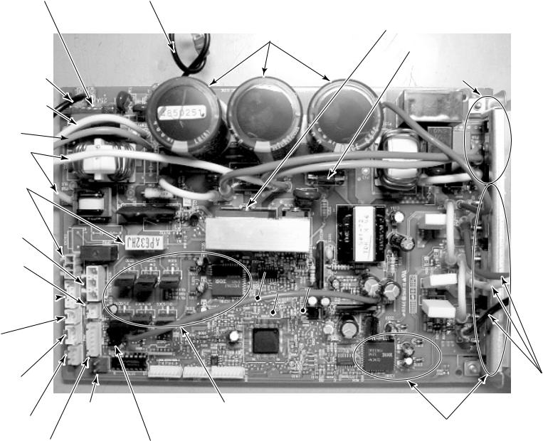
– 30 –
F01, 02, 25A fuse |
Lead wire for grounding |
|
(Black) |
L-phase power supply lead (Black)
N-phase power supply lead (White)
Serial lead (Orange) 
Reactor lead connector (White)
CN701:
4-way valve connector
RY701:
4-way valve relay
CN300:
Fan motor connector
CN602:
Outdoor temperature (TO) sensor connector
CN806:
Optional connector 
CN600: |
|
|
Heat exchange temperature |
|
|
(TE) sensor connector |
|
|
CN603: |
|
|
Suction temperature |
|
|
(TS) sensor connector |
|
|
CN601: |
CN500: |
|
Discharge temperature |
||
Case thermo. or |
||
(TD) sensor connector |
||
High pressure SW |
||
|
C12, 13, 14 electrolytic capacitor
12V
5V
GND
IC800: MCU
Fan drive circuit
Q300 to Q305: FET (QTY: 6P)
CN700: |
CN605: |
PMV connector |
Sub SW board connector |
DB02: |
UL-SP180AT2RAV- |
5009><MCC- |
CircuitPrint.17- |
High power factor diode |
|||
Q404: |
|||
High power factor circuit IGBT |
|
|
|
F03: 3.15A fuse |
|
|
|
DB01: |
|
|
|
Single-phase rectifier diode |
|
|
Board |
|
|
|
Comp. lead
(Red) (White) (Black)
Comp. drive circuit
Q200 to Q205: IGBT (QTY: 6P)
IC200: Drive IC (QTY: 1P)
SPECIFICATIONS CONTROL AND CONFIGURATION CIRCUIT .7
 Loading...