


Toshiba MMY-MAP1446FT9P-UL, MMY-MAP0726FT9P-UL, MMY-MAP1686FT9P-UL, MMY-MAP0966FT9P-UL, MMY-MAP1206FT9P-UL User Manual
AIR CONDITIONER (MULTI TYPE)
Installation Manual
Outdoor Unit
Model name:
<Heat Recovery Model>
MMY-MAP0726FT9P-UL MMY-MAP0966FT9P-UL MMY-MAP1206FT9P-UL MMY-MAP1446FT9P-UL MMY-MAP1686FT9P-UL
For OUTDOOR USE only
Pour une UTILISATION EN EXTÉRIEUR uniquement
1122001101
Installation Manual |
1 |
English |
|
|
|
|
|
|
Manuel d’installation |
32 |
Français |
|
|
|

ADOPTION OF NEW REFRIGERANT
This Air Conditioner uses R410A an environmentally friendly refrigerant.
Contents
1 Precautions for safety . . . . . . . . . . . . . . . . . . . . . . . . . . . . . . . . . . . . . . . . . . . . . . . . . . 2 2 Accessory parts . . . . . . . . . . . . . . . . . . . . . . . . . . . . . . . . . . . . . . . . . . . . . . . . . . . . . . . 3 3 Installation of R410 air conditioner. . . . . . . . . . . . . . . . . . . . . . . . . . . . . . . . . . . . . . . . 3 4 Selection of installation place. . . . . . . . . . . . . . . . . . . . . . . . . . . . . . . . . . . . . . . . . . . . 4 5 Carrying in the outdoor unit . . . . . . . . . . . . . . . . . . . . . . . . . . . . . . . . . . . . . . . . . . . . . 5 6 Installation of the outdoor unit . . . . . . . . . . . . . . . . . . . . . . . . . . . . . . . . . . . . . . . . . . . 6 7 Refrigerant piping. . . . . . . . . . . . . . . . . . . . . . . . . . . . . . . . . . . . . . . . . . . . . . . . . . . . . . 8 8 Electric wiring. . . . . . . . . . . . . . . . . . . . . . . . . . . . . . . . . . . . . . . . . . . . . . . . . . . . . . . . 16 9 Address setting . . . . . . . . . . . . . . . . . . . . . . . . . . . . . . . . . . . . . . . . . . . . . . . . . . . . . . 19 10 Test run . . . . . . . . . . . . . . . . . . . . . . . . . . . . . . . . . . . . . . . . . . . . . . . . . . . . . . . . . . . . . 27 11 Troubleshooting . . . . . . . . . . . . . . . . . . . . . . . . . . . . . . . . . . . . . . . . . . . . . . . . . . . . . . 29
– 1 –
Installing, starting up, and servicing air conditioning equipment can be hazardous due to system pressures, electrical components, and equipment location (roofs, elevated structures, etc.).
Only trained, qualified installers and service mechanics should install, start up, and service this equipment. Untrained personnel can perform basic maintenance functions such as indoor unit air filter. All other operations should be performed by trained service personnel.
Before working on the equipment, observe precautions in the literature and on tags, stickers, and labels attached to the equipment.
Follow all safety codes. Wear safety glasses and work gloves. Use care in handling, rigging, and setting bulky equipment.
Read these instructions thoroughly and follow all warnings or cautions included in literature and attached to the unit. Consult local building codes and National Electrical Code (NEC) for special requirements. Recognize safety information. This is the safety alert symbol  . When you see this symbol on the unit and in instructions or manuals, be alert to the potential for personal injury. Understand these signal words: DANGER, WARNING, and CAUTION. These words are used with the safety alert symbol.
DANGER identifies the most serious hazards which will result in severe personal injury or death. WARNING signifies hazards which could result in personal injury or death. CAUTION is used to identify unsafe practices which may result in minor personal injury or product and property damage. NOTE is used to highlight suggestions which will result in enhanced installation, reliability, or operation.
1-EN |
2-EN |

1 Precautions for safety
The manufacturer shall not assume any liability for the damage caused by not observing the description of this manual.
 WARNING
General
•Carefully read Owner’s Manual before starting the air conditioner. There are many important things to keep in mind for daily operation.
•Ask for installation to be performed by the dealer or a professional. Only a qualified installer is able to install an air conditioner. If a non-qualified person installs an air conditioner, it may result in problems such as fire, electric shock, injury, water leakage, noise and vibration.
•Do not use any refrigerant different from the one specified for complement or replacement.
Otherwise, abnormally high pressure may be generated in the refrigeration cycle, which may result in a failure or explosion of the product or an injury to your body.
•Before opening the service panel of the outdoor unit, set the circuit breaker to the OFF position. Failure to set the circuit breaker to the OFF position may result in electric shocks through contact with the interior parts.
•Before carrying out the installation, maintenance, repair or removal work, be sure to set the circuit breakers for both the indoor and outdoor units to the OFF position. Otherwise, electric shock may result.
•Wear protective gloves and safety work clothing during installation, servicing and removal.
•Do not touch the aluminium fin of the outdoor unit. You may injure yourself if you do so. If the fin must be touched for some reason, first put on protective gloves and safety work clothing, and then proceed.
•Do not climb onto or place objects on top of the outdoor unit. You may fall or the objects may fall off of the outdoor unit and result in injury.
•Before cleaning the filter or other parts of the outdoor unit, set the circuit breaker to OFF without fail, and place a “Work in progress” sign near the circuit breaker before proceeding with the work.
•The refrigerant used by this air conditioner is the R410A.
•The air conditioner must be transported in stable condition. If any part of the product are broken, contact your distributor.
Selection of installation location
•Do not install in a location where flammable gas leaks are possible. If the gas should leak and accumulate around the unit, it may ignite and cause a fire.
•During transporting the air conditioner, wear shoes with protective toe caps, protective gloves, and other protective clothing.
•To transport the air conditioner, do not take hold of the bands around the packing carton. You may injure yourself if the bands should break.
•Places where the operation sound of the outdoor unit may cause a disturbance. (Especially at the boundary line with a neighbour, install the air conditioner while considering the noise.)
Installation
•The designated bolts (M12) and nuts (M12) for securing the outdoor unit must be used when installing the unit.
•Install the outdoor unit property in a location that is durable enough to support the weight of the outdoor unit. Insufficient durability may cause the outdoor unit to fall, which may result in injury.
•Install the unit in the prescribed manner for protection against strong wind and earthquake. Incorrect installation may result in the unit falling down, or other accidents.
•Fix the screws back which have been removed for installation or other purposes.
Refrigerant piping
•Install the refrigerant pipe securely during the installation work before operating the air conditioner. If the compressor is operated with the valve open and without refrigerant pipe, the compressor sucks air and the refrigeration cycles is over pressurized, which may cause a injury.
•Tighten the flare nut with a torque wrench in the specified manner. Excessive tighten of the flare nut may cause a crack in the flare nut after a long period, which may result in refrigerant leakage.
•Ventilate the air if the refrigerant gas leaks during installation. If the leaked refrigerant gas comes into contact with fire, toxic gas may be produced.
•When the air conditioner has been installed or relocated, follow the instructions in the Installation Manual and purge the air completely so that no gases other than the refrigerant will be mixed in the refrigerating cycle. Failure to purge the air completely may cause the air conditioner to malfunction.
•Nitrogen gas must be used for the airtight test.
Electrical wiring
•Only a certified installer or qualified service person is allowed to carry out the electrical work of the air conditioner.
•When connecting the electrical wires, repairing the electrical parts or undertaking other electrical jobs, wear gloves to provide protection for electricians and from heat, insulating shoes and clothing to provide protection from electric shocks. Failure to wear this protective gear may result in electric shocks.
•When executing address setting, test run, or troubleshooting through the checking window on the electric parts box, put on insulated heat-proof gloves, insulated shoes and other clothing to provide protection from electric shock. Otherwise you may receive an electric shock.
•Use wiring that meets the specifications in the Installation Manual, NEC and the local codes.
•Check that the product is properly grounded.
•Do not connect the ground line to a gas pipe, water pipe, lightning conductor, or a telephone ground line.
•After completing the repair or relocation work, check that the ground wires are connected properly.
•Install a circuit breaker that meets the specifications in the installation manual, NEC and local codes.
•Under no circumstances must the power cable be extended. Connection trouble in the places where the cable is extended may give rise to smoking and/or a fire.
•Do not supply power from the power terminal block equipped on the outdoor unit to another outdoor unit. Capacity overflow may occur on the terminal block and may result in fire.
•Each outdoor unit should have its own power supply.
Test run
•Before operating the air conditioner after having completed the work, check that the electrical parts box cover of the indoor unit and service panel of the outdoor unit are closed, and set the circuit breaker to the ON position. You may receive an electric shock if the power is turned on without first conducting these checks.
•If there is any kind of trouble (such as when a check code display has appeared, there is a smell of burning, abnormal sounds are heard, the air conditioner fails to cool or heat or water is leaking) has occurred in the air conditioner, do not touch the air conditioner yourself but set the circuit breaker to the OFF position, and contact a qualified service person.
Take steps to ensure that the power will not be turned on (by marking “out of service” near the circuit breaker, for instance) until qualified service person arrives. Continuing to use the air conditioner in the trouble status may cause mechanical problems to escalate or result in electric shocks or other failure.
•Upon completion of the installation work, check for refrigerant leaks and check the insulation resistance and water drainage. Then conduct a test run to check that the air conditioner is operating properly.
Explanations given to user
•Upon completion of the installation work, tell the user where the circuit breaker is located. If the user does not know where the circuit breaker is, he or she will not be able to turn it off in the event that trouble has occurred in the air conditioner.
•If the fan grille is damaged, do not approach the outdoor unit but set the circuit breaker to the OFF position, and contact a qualified service person to have the repairs done. Do not set the circuit breaker to the ON position until the repairs are completed.
•After the installation work, follow the Owner’s Manual to explain to the customer how to use and maintain the unit.
Relocation
•Only a certified installer or service person is allowed to relocate the air conditioner.
•When the pump-down work is carried out shut down the compressor before disconnecting the refrigerant pipe. Disconnecting the refrigerant pipe with the service valve left open and the compressor still operating will cause air or other gas to be sucked in, raising the pressure inside the refrigeration cycle to an abnormally high level, and possibly resulting in rupture, injury or other trouble.
•Do not recover the refrigerant into the outdoor unit. Use a refrigerant recovery machine to recover the refrigerant after moving or repairing. It is impossible to recover the refrigerant into the outdoor unit. Refrigerant recovery into the outdoor unit may result in serious accidents such as explosion of the unit, injury or other accidents.
 CAUTION
New Refrigerant Air Conditioner Installation
•THIS AIR CONDITIONER USES THE ENVIRONMENTALLY FRIENDLY HFC REFRIGERANT (R410A) WHICH DOES NOT DESTROY OZONE LAYER.
•The characteristics of R410A refrigerant are; easy to absorb water, oxidizing membrane or oil, and its pressure is approx. 1.6 times higher than that of refrigerant R22. Accompanied with the new refrigerant, refrigerating oil has also been changed.
Therefore, during installation work, be sure that water, dust, former refrigerant, or refrigerating oil does not enter the refrigerating cycle.
•To prevent charging an incorrect refrigerant and refrigerating oil, the sizes of connecting sections of charging port of the main unit and installation tools are changed from those for the conventional refrigerant.
•For connecting pipes, use new and clean piping designed for R410A, and please care so that water or dust does not enter.
EN
FR
3-EN |
– 2 – |
4-EN |
|
|
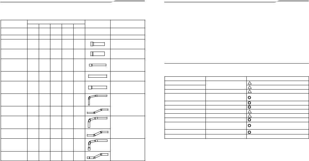
2 |
Accessory parts |
|
|
|
|
||||
Part name |
|
|
Q’ty |
|
|
Shape |
Usage |
||
MAP072 |
MAP096 |
MAP120 |
MAP144 |
MAP168 |
|||||
|
|
|
|
||||||
Owner’s Manual |
1 |
1 |
1 |
1 |
1 |
– |
(Be sure to hand it to the |
||
customers.) |
|||||||||
|
|
|
|
|
|
|
|
||
Installation Manual |
1 |
1 |
1 |
1 |
1 |
– |
This manual for installer. |
||
Attached pipe |
|
|
|
|
|
|
Suction-side gas pipe |
||
(Ø7/8" both forward |
1 |
1 |
– |
– |
– |
|
|||
|
Ø1"→Ø7/8" pipe fitting |
||||||||
and downward) |
|
|
|
|
|
|
|||
|
|
|
|
|
|
|
|||
Attached pipe |
|
|
|
|
|
|
Suction-side gas pipe |
||
(Ø1 1/8" both forward |
– |
– |
1 |
1 |
1 |
|
|||
|
Ø1"→Ø1 1/8" pipe fitting |
||||||||
and downward) |
|
|
|
|
|
|
|||
|
|
|
|
|
|
|
|||
Attached pipe |
|
|
|
|
|
|
Discharge-side gas pipe |
||
|
|
|
|
|
|
Ø5/8"→Ø3/4" pipe fitting |
|||
(Ø3/4" both forward |
1 |
– |
– |
– |
– |
|
|||
|
* Flare the connector on the |
||||||||
and downward) |
|
|
|
|
|
|
|||
|
|
|
|
|
|
outdoor unit for installation. |
|||
|
|
|
|
|
|
|
|
||
Attached pipe |
|
|
|
|
|
|
Discharge-side gas pipe |
||
(Ø3/4" both forward |
– |
1 |
1 |
– |
– |
|
* Flare the connector on the |
||
and downward) |
|
|
|
|
|
|
outdoor unit for installation. |
||
Attached pipe |
|
|
|
|
|
|
Discharge-side gas pipe |
||
|
|
|
|
|
|
Ø3/4"→Ø7/8" pipe fitting |
|||
(Ø7/8" both forward |
– |
– |
– |
1 |
1 |
|
|||
|
* Flare the connector on the |
||||||||
and downward) |
|
|
|
|
|
|
|||
|
|
|
|
|
|
outdoor unit for installation. |
|||
|
|
|
|
|
|
|
|
||
Attached pipe |
|
|
|
|
|
|
|
||
(Ø1/2" for draw-out |
1 |
1 |
1 |
– |
– |
|
Liquid pipe |
||
forward) |
|
|
|
|
|
|
|
||
|
|
|
|
|
|
|
|
* Flare the connector on the |
|
Attached pipe |
|
|
|
|
|
|
outdoor unit for installation. |
||
(Ø1/2" for draw-out |
1 |
1 |
1 |
– |
– |
|
|
||
downward) |
|
|
|
|
|
|
|
||
Attached pipe |
|
|
|
|
|
|
|
||
(Ø5/8" for draw-out |
– |
– |
– |
1 |
– |
|
Liquid pipe |
||
forward) |
|
|
|
|
|
|
|
||
|
|
|
|
|
|
|
|
* Flare the connector on the |
|
Attached pipe |
|
|
|
|
|
|
outdoor unit for installation. |
||
(Ø5/8" for draw-out |
– |
– |
– |
1 |
– |
|
|
||
downward) |
|
|
|
|
|
|
|
||
Attached pipe |
|
|
|
|
|
|
|
||
(Ø3/4" for draw-out |
– |
– |
– |
– |
1 |
|
Liquid pipe |
||
forward) |
|
|
|
|
|
|
|
Ø5/8"→Ø3/4" pipe fitting |
|
Attached pipe |
|
|
|
|
|
|
* Flare the connector on the |
||
– |
– |
– |
– |
1 |
|
outdoor unit for installation. |
|||
(Ø3/4" for draw-out |
|
|
|||||||
downward) |
|
|
|
|
|
|
|
||
– 3 –
3 Installation of R410 air conditioner
This air conditioner adopts the HFC refrigerant (R410A) which does not deplete the ozone layer.
•R410A refrigerant is vulnerable to impurities such as water, oxidizing membranes, or oils because the pressure of R410A refrigerant is higher than that of the former refrigerant by approximately 1.6 times.
As well as the adoption of the new refrigerant, the refrigerating oil has been also changed. Therefore, pay attention so that water, dust, former refrigerant, or refrigerating oil does not enter the refrigerating cycle of the new refrigerant air conditioner during installation.
•To prevent mixing of refrigerant or refrigerating oil, the size of the charge port of the main unit or connecting section of the installation tool differs to that of an air conditioner for the former refrigerant.
Accordingly, exclusive tools are required for the new refrigerant (R410A) as shown below.
•For connecting pipes, use new and clean piping materials so that water or dust does not enter.
■ Required Tools and Cautions on handling
Prepare the tools and equipment listed in the following table before starting the installation work.  : R410A exclusive
 : Generic
Tools/equipment |
Use |
|
Manifold gauge* |
Vacuuming/charging refrigerant |
|
Charging hose |
and operation check |
|
Gas leak detector |
Gas leak check |
|
Vacuum pump with backflow |
Vacuum drying |
|
prevention function |
|
|
|
|
|
Flare tool |
Flare machining of pipes |
Usable if dimensions are adjusted. |
Bender |
Bending pipes |
|
Refrigerant recovery equipment |
Refrigerant recovery |
|
Torque wrench |
Tightening flare nuts |
Ø1/2" (12.7 mm) and Ø5/8" (15.9 mm) |
Pipe cutter |
Cutting pipes |
|
Brazing torch and nitrogen |
Braze pipes |
|
cylinder |
|
|
|
|
|
Refrigerant charging scales |
Charging refrigerant |
|
4 mm hexagon wrench |
Opening liquid valve |
|
5-EN |
6-EN |
4 Selection of installation place
Upon customer’s approval, install the air conditioner in a place which satisfies the following conditions:
•Place where it can be installed horizontally.
•Place which can reserve a sufficient service space for safe maintenance or checks.
•Place where there is no problem even if the drained water overflows.
Avoid the following places:
•Salty places (seaside area) or places with much gas sulfide (hot spring area) (If selecting such a place, special maintenance is required.)
•Places where oil (including machine oil), steam, oil smoke or corrosive gas is generated.
•Places where an organic solvent is used.
•Chemical plants with a cooling system using liquid carbon dioxide.
•Places where a device generating high frequency (inverter, non-utility generator, medical apparatus, or communication equipment) is set. (Malfunction or abnormal control of the air conditioner, or interference to devices listed above may occur.)
•Places where discharged air from the outdoor unit blows against the windows of a neighbour’s house.
•Places unable to bear the weight of the unit.
•Places with poor ventilation.
•The unit will operate down to an outdoor temperature of 13 °F, however considerable performance decrease will be expected below 5 °F. Therefore please consider installation location/surroundings and system design when expected to operate between 5 °F and 13 °F.
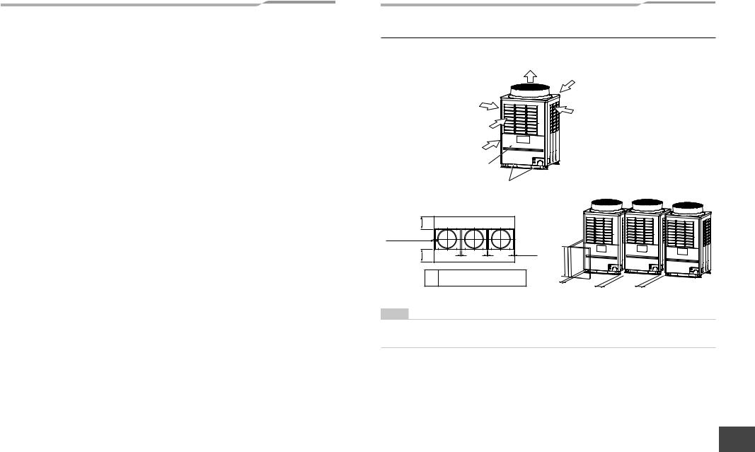
■ Installation space
Unit: in (mm)
Leave space necessary for running, installation and servicing.
Air discharge
Air intake
Air intake
Air intake
Air intake
Installation/servicing surface
Square hole for handling
(Rear side) |
Outdoor unit top view |
|
19.7" (500) |
|
|
|
or more |
|
|
|
0.4" (10) or more |
|
|
0.4" (10) |
|
|
|
|
19.7" (500) |
|
|
or more |
or more |
L |
L |
31.5" (800) |
(Front side) |
|
|
|
|
|
or less |
L Recommendation 7.9" (200mm),
at least 0.8" (20mm) or more.
0.4" (10) or more |
L |
L |
NOTE
•If there is an obstacle above the outdoor unit, leave a space of 78.7" (2000) or more to the top end of the outdoor unit.
•If there is a wall around the outdoor unit, make sure that its height does not exceed 31.5" (800).
EN
FR
7-EN |
– 4 – |
8-EN |
|
|
– 5 –
▼Combination of outdoor units
Model name |
Unit 1 |
Unit 2 |
Unit 3 |
(Standard Model) |
Header unit |
Follower unit |
Follower unit |
MMY-MAP0726FT9P-UL |
MMY-MAP0726* |
– |
– |
MMY-MAP0966FT9P-UL |
MMY-MAP0966* |
– |
– |
MMY-MAP1206FT9P-UL |
MMY-MAP1206* |
– |
– |
MMY-MAP1446FT9P-UL |
MMY-MAP1446* |
– |
– |
MMY-MAP1686FT9P-UL |
MMY-MAP1686* |
– |
– |
MMY-AP1926FT9P-UL |
MMY-MAP0966* |
MMY-MAP0966* |
– |
MMY-AP2166FT9P-UL |
MMY-MAP1206* |
MMY-MAP0966* |
– |
MMY-AP2406FT9P-UL |
MMY-MAP1446* |
MMY-MAP0966* |
– |
MMY-AP2646FT9P-UL |
MMY-MAP1446* |
MMY-MAP1206* |
– |
MMY-AP2886FT9P-UL |
MMY-MAP1446* |
MMY-MAP1446* |
– |
MMY-AP3126FT9P-UL |
MMY-MAP1686* |
MMY-MAP1446* |
– |
MMY-AP3366FT9P-UL |
MMY-MAP1206* |
MMY-MAP1206* |
MMY-MAP0966* |
MMY-AP3606FT9P-UL |
MMY-MAP1206* |
MMY-MAP1206* |
MMY-MAP1206* |
MMY-AP3846FT9P-UL |
MMY-MAP1446* |
MMY-MAP1206* |
MMY-MAP1206* |
MMY-AP4086FT9P-UL |
MMY-MAP1446* |
MMY-MAP1446* |
MMY-MAP1206* |
MMY-AP4326FT9P-UL |
MMY-MAP1446* |
MMY-MAP1446* |
MMY-MAP1446* |
MMY-AP4566FT9P-UL |
MMY-MAP1686* |
MMY-MAP1446* |
MMY-MAP1446* |
Model name |
Unit 1 |
Unit 2 |
Unit 3 |
(Space Saving Model) |
Header unit |
Follower unit |
Follower unit |
MMY-AP192S6FT9P-UL |
MMY-MAP1206* |
MMY-MAP0726* |
– |
MMY-AP240S6FT9P-UL |
MMY-MAP1206* |
MMY-MAP1206* |
– |
MMY-AP288S6FT9P-UL |
MMY-MAP1686* |
MMY-MAP1206* |
– |
MMY-AP336S6FT9P-UL |
MMY-MAP1686* |
MMY-MAP1686* |
– |
5 Carrying in the outdoor unit
 CAUTION
Handle the outdoor unit carefully, observing the following items.
•To use a forklift or other machinery for loading/unloading in transportation, insert the fork of the forklift into the rectangular holes for handling as shown below.
•To lift up the unit, insert a rope capable of bearing the weight of the unit into the rectangular holes shown below. Tie the unit from 4 sides.
(Apply padding in positions where the rope comes in contact with the outdoor unit so that no damage is caused to the outer surface of the outdoor unit.)
(There are reinforcing plates on the side surfaces, so the rope cannot be passed through.)
|
Correct |
|
Incorrect |
Incorrect |
|
|
Plaster |
|
|
|
|
board |
|
|
|
|
Rope |
|
|
Rectangular |
Side |
Plaster |
|
|
holes for |
|
board |
|
|
handling |
|
|
|
|
Front/Back |
Incorrect |
|
|
|
|
|
|
|
|
|
|
Rectangular |
Reinforcing |
|
|
|
holes for |
||
Correct |
|
plate |
|
|
|
lifting |
|
||
|
|
|
||
Fork of the forklift
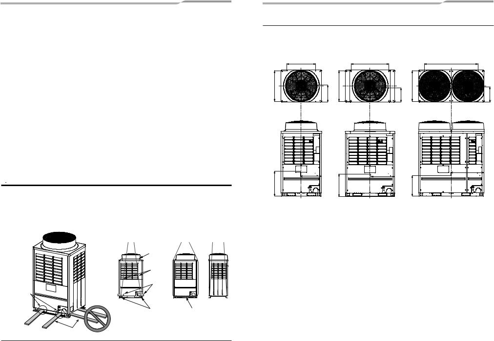
■ Weight center and weight
Unit: in (mm)
Weight center of an outdoor unit
(A) |
Anchor bolt position |
(B) |
Anchor bolt position |
(C) |
Anchor bolt position |
|
27.6" (700) |
|
36.2" (920) |
|
51.6" (1310) |
Anchor bolt position |
29.7" (755) |
Y Anchor bolt position |
29.7" (755) |
Y Anchor bolt position |
29.7" (755) |
Y |
|
X |
Z |
Z |
X |
Z |
X |
No. |
Model type |
X |
Y |
Z |
Weight |
|
(in(mm)) |
(in(mm)) |
(in(mm)) |
(lb(kg)) |
|||
|
|
|||||
(A) |
MAP0726FT9P-UL |
20.5" (520) |
15.4" (390) |
24.0" (610) |
600 (272) |
|
(B) |
MAP0966FT9P-UL |
23.8" (605) |
15.7" (400) |
23.2" (590) |
721 (327) |
|
MAP1206FT9P-UL |
||||||
|
|
|
|
|
||
(C) |
MAP1446FT9P-UL |
30.3" (770) |
16.3" (415) |
22.4" (570) |
882 (400) |
|
MAP1686FT9P-UL |
||||||
|
|
|
|
|
9-EN |
10-EN |
6 Installation of the outdoor unit
 WARNING
Install the outdoor unit securely in a location where the base can sustain the weight adequately.
If strength is insufficient, the unit may fall down resulting in human injury.
 CAUTION
•Drain water is discharged from the outdoor unit. (Especially while heating) Install the outdoor unit in a place with good drainage.
•For installation, be careful of the strength and level of the foundation so that abnormal sounds (vibration or noise) are not generated.
REQUIREMENT
Installation in a snowfall area
1.Install the outdoor unit on a higher foundation than the snowfall or set up a stand to install the unit so that snowfall will not affect the unit.
•Set up a stand higher than the snowfall.
•Apply an angled structure to the stand so that drainage will not be prevented. (Avoid using a stand with a flat surface.)
2.Mount a snowfall-hood onto the air inlet and the air outlet.
•Leave enough space for the snowfall-hood so that it will not be an obstacle for the air inlet and the air outlet.
Snowfall-hood for air  outlet (locally procured)
Snowfall-hood for air
 outlet
(4 faces)
 (locally procured)
Stand
 (locally procured)
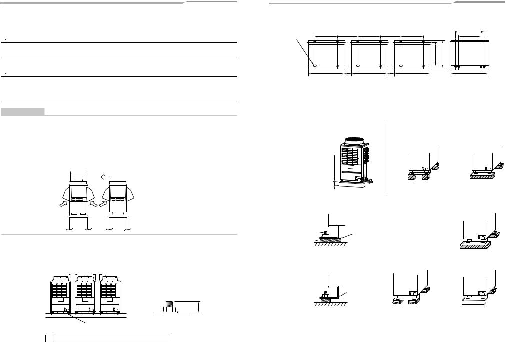
1.To install multiple outdoor units, arrange them with 7.9" (200mm) (recommendation, at least 0.8" (20mm)) or more spaces in between.
Fix each outdoor unit with M12 anchor bolts at 4 positions. 0.8" (20mm) projection is appropriate for an anchor bolt.
Unit: in (mm)
L L
• Anchor bolt positions are as shown below:
Continuous hole |
A |
L+11.4" (290) |
A |
L+11.4" (290) |
A |
C* |
(0.6" × 0.8" (15 × 20) |
|
|
A |
|||
|
|
|
|
|
||
long hole) |
|
|
|
|
|
|
|
|
|
|
|
29.7" (755) |
31.1" (790) |
B |
L |
B |
L |
B |
B |
*Only MAP144, MAP168 type has holes for additional strength.
Model type |
A |
B |
C |
L |
|
MAP0726 |
27.6" (700) |
39.0" (990) |
– |
Recommendation 7.9" (200), |
|
MAP0966, MAP1206 |
36.2" (920) |
47.6" (1210) |
– |
||
at least 0.8" (20) or more |
|||||
MAP1446, MAP1686 |
51.6" (1310) |
63.0" (1600) |
59.0" (1500) |
||
|
2. To draw out the refrigerant pipe from the underside, |
3. Do not use 4 stands on the corner to support the |
|
set the height of the stand to 19.7" (500mm) or more. |
outdoor unit. |
|
19.7" (500mm) or more |
Incorrect |
Correct |
|
|
|
4. If vibration-proof rubbers (including vibration-proof blocks) are used, fit them under the whole clamping legs.
Correct |
|
Correct |
Anchor bolt |
Install the vibration-proof |
|
Vibration-proof rubber |
rubber so that the bend part |
|
of the fixing leg is |
|
|
|
grounded. |
|
Incorrect |
Incorrect |
Incorrect |
0.8" (20)
M12 anchor bolt
4 positions/unit
L Recommendation 7.9" (200mm), at least 0.8" (20mm) or more.
11-EN
The bend part of the fixing leg is not grounded.
|
|
|
|
|
|
|
|
|
|
|
|
5. Be careful of the connecting arrangement of the header unit and follower units. Set the outdoor units in order of |
EN |
||||||||||
capacity from the one with the largest capacity. (A (Header unit) ≥ B ≥ C) |
|
||||||||||
• Be sure to use a header unit for the leading outdoor unit to be connected to the main pipe. (Figure 1, 3 and 6)
• Be sure to use a T-shaped branch joint (RBM-BT14FUL/RBM-BT24FUL: separately purchased) to connect each FR outdoor unit.
• Be careful of the direction of the outdoor unit connection piping kit for the liquid side. (As shown in Figure 2, an outdoor unit connection piping kit cannot be attached so that the refrigerant of the main pipe flows directly into
the header unit.)
12-EN
– 6 –

Discharge side gas piping / Liquid piping
▼Figure 1 |
|
|
▼Figure 2 |
|
|
Correct |
|
|
Incorrect |
|
|
Header unit |
|
|
Header unit |
|
|
A |
Follower unit |
|
A |
Follower unit |
|
|
|
|
|
||
|
B |
Follower unit |
|
B |
Follower unit |
|
|
C |
|
|
C |
 Main pipe
To the indoor unit
Suction side gas piping
▼Figure 3
Correct
Header unit
A Follower unit
B Follower unit
C
Incorrect 
Main pipe
To the indoor unit
[Inverse connection of a gas-side branch unit]
▼Figure 4
Incorrect
Header unit
A Follower unit
B Follower unit
C
– 7 –
When drawing pipes downward
▼Figure 5
Incorrect
Header unit
AFollower unit B
|
A view |
|
Suction gas joint |
Main |
Unit |
|
|
pipe |
|
To |
|
the |
|
indoor |
|
unit |
Vertical line |
Suction gas joint |
A |
[Vertical connection of branch units]
▼Figure 6 |
|
▼Figure 7 |
Correct |
|
Incorrect |
|
Header unit |
|
|
A |
Follower unit |
|
|
BFollower unit C
Main |
pipe |
|
|
Main |
|
||
To |
the |
|
To |
pipe |
|||
indoor |
|
||||||
|
|
the |
|
||||
|
|
unit |
|
indoor |
|||
|
|
|
|
||||
|
|
|
|
|
|
|
unit |
|
|
|
|
Branch |
|
|
|
|
|
|
|
unit |
|
|
To gas-side branch unit |
|
|
|
|
|
|
|
|
•When attaching a Y-shaped branch unit for the outdoor unit connection piping kit, attach it level with the ground (Be sure not to exceed ±15 degrees.). Regarding a T-shape branch joints for the liquid side, there is no restriction for its angle.
At a level position
|
(Horizontal line) |
(Horizontal line) |
A |
Within ±15 degrees |
|
(A arrow view) |
(B arrow view) |
|
|
B |
|
•In case of using the Y-shaped branching joint for connecting between outdoor units (Discharge gas joint and Suction gas joint), please keep the straight part of at least 19.7" (500mm) at the inlet.
Within ±15 |
Do not connect |
||
a branch unit |
|||
degrees |
|||
vertically. |
|||
|
|
||
|
.7" |
|
|
19 |
|
||
(500mm) |
|
||
or |
more |
|
|
|
|
||
13-EN
L- |
|
shaped |
|
pipe |
|
To |
|
gas- |
|
|
side |
|
branch |
|
unit |
To gas-side |
To gas-side |
branch unit |
branch unit |
14-EN
7 Refrigerant piping
 WARNING
•If the refrigerant gas leaks during installation, ventilate the room.
If the leaked refrigerant gas comes into contact with fire, noxious gas may be generated.
•After installation, check that the refrigerant gas does not leak.
If the refrigerant gas leaks into the room and comes into contact with fire such as a fan heater, stove, or kitchen range, noxious gas may be generated.
■ Connection of refrigerant pipe
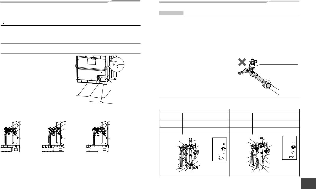
•The service valves are inside the outdoor unit. To access them, remove the front panel and the piping/ wiring panel. (M5: 9 pcs.)
•As shown in the illustration on the right, the hooks are at the right and left sides of the front panel. Lift up and remove the front panel.
•Pipes can be drawn out forward or downward from the outdoor unit.
•To draw out the pipe forward, draw it out to the outside via the piping/wiring panel, and leave a space of 19.7" (500mm) or more from the main pipe connecting the outdoor unit with the indoor unit, considering service work or other work on the unit. (For replacing the compressor, 19.7" (500mm)
or more space is required.)
•To draw out the pipe downward, remove the knockouts on the base plate of the outdoor unit, draw the pipes out of the outdoor unit, and perform piping on pipe should be 16.4 ft (5m) or less.
19 |
.7" |
|
or |
||
|
(500mm) |
(Left |
(Right |
|
more |
piping) |
||
piping) |
|||
Drawing out |
|
||
|
forward |
||
 Hook
Hook
 Front panel


 Piping/wiring panel
(Rear piping)
(Left piping) |
Drawing out |
(Right piping) |
|
|
|
|
downward |
|
the right/left or rear side. Downward length of the balance
(MAP072) |
Packed valve of liquid side
Ball valve of suction gas side |
Packed valve of |
balance pipe |
Ball valve of |
discharge gas pipe |
(MAP096, 120) |
Packed valve of liquid side |
Ball valve of suction gas side |
Packed valve of |
balance pipe |
Ball valve of |
discharge gas pipe |
(MAP144, 168) |
Packed valve of liquid side Ball valve of suction gas side
Packed valve of balance pipe
Ball valve of discharge gas pipe
REQUIREMENT
•For a brazing work of the refrigerant pipes, be sure to use nitrogen gas in order to prevent oxidation of the inside of the pipes; otherwise clogging of the refrigerating cycle due to oxidized scale may occur.
•Use clean and new pipes for the refrigerant pipes and perform piping work so that water or dust does not contaminate the refrigerant.
•Be sure to use two spanners to loosen or tighten the flare nut. If a single spanner is used, the required level of tightening cannot be obtained. Tighten the flare nut with the specified torque. (If it is hard to loosen or tighten the flare nut of the balance pipe or packed valve of the liquid side with two spanners, loosen or tighten the flare nut while holding the valve mounting plate with a spanner.)
|
Unit: ft•lbs (N•m) |
|
Outer dia. of |
Tightening torque |
|
copper pipe |
||
|
||
Ø1/4 (6.4 mm) |
10 to 13 (14 to 18) |
|
Ø3/8 (9.5 mm) |
24 to 31 (33 to 42) |
|
Ø1/2 (12.7 mm) |
37 to 46 (50 to 62) |
|
Ø5/8 (15.9 mm) |
50 to 60 (68 to 82) |
|
Ø3/4 (19.1 mm) |
74 to 88 (100 to 120) |
Do not apply refrigerating oil to the surface of the flare.
Ball valve of discharge gas side


 Do not clamp the service port
with two spanners, doing so may damage the service port.
Pipe connection method (Example)
|
Draw-out forward |
|
|
Draw-out downward |
|
|||
Suction-side gas |
Cut the L-shaped pipe, then braze the |
Suction-side gas |
Cut the L-shaped pipe, then braze the |
|||||
pipe |
socket procured locally. |
|
pipe |
socket procured locally. |
|
|||
Discharge-side |
Braze the supplied attachment pipe |
Discharge-side |
Braze the supplied attachment pipe |
|||||
gas pipe |
and elbow procured locally. |
gas pipe |
and socket procured locally. |
|||||
Liquid pipe |
Braze the supplied attachment pipe |
Liquid pipe |
Braze the supplied attachment pipe |
|||||
and socket procured locally. |
and socket procured locally. |
|||||||
|
|
|||||||
Discharge-side |
|
Discharge-side |
|
Suction-side |
Suction-side |
|||
|
gas pipe |
|
|
|||||
gas pipe |
Suction-side |
Suction-side |
|
|
||||
|
gas pipe |
gas pipe |
Liquid pipe |
|
|
gas pipe |
gas pipe |
|
|
|
|
|
|
||||
Liquid pipe |
Balance |
|
|
|
|
Balance |
|
|
pipe |
|
|
|
|
pipe |
Section |
||
|
|
|
|
|
||||
|
L-shaped |
|
|
|
|
|
||
|
Section |
|
|
|
|
to be cut |
||
|
pipe |
|
|
|
|
|||
|
to be cut |
|
|
|
Pipe |
|
||
|
Pipe |
Attachment |
|
|
|
|||
Attachment |
|
|
|
L-shaped |
|
|||
|
|
pipe |
|
|
|
|||
pipe |
Socket |
|
Attachment |
|
|
pipe |
|
|
Attachment |
Pipe |
|
pipe |
|
|
Socket |
|
|
pipe |
|
|
|
|
Pipe |
|
||
Elbow |
|
|
Socket |
|
|
|||
|
|
|
|
|
||||
Socket |
Pipe Pipe |
|
Pipe |
Socket |
|
|||
|
|
Pipe |
|
|||||
EN
FR
15-EN |
– 8 – |
16-EN |
|
|
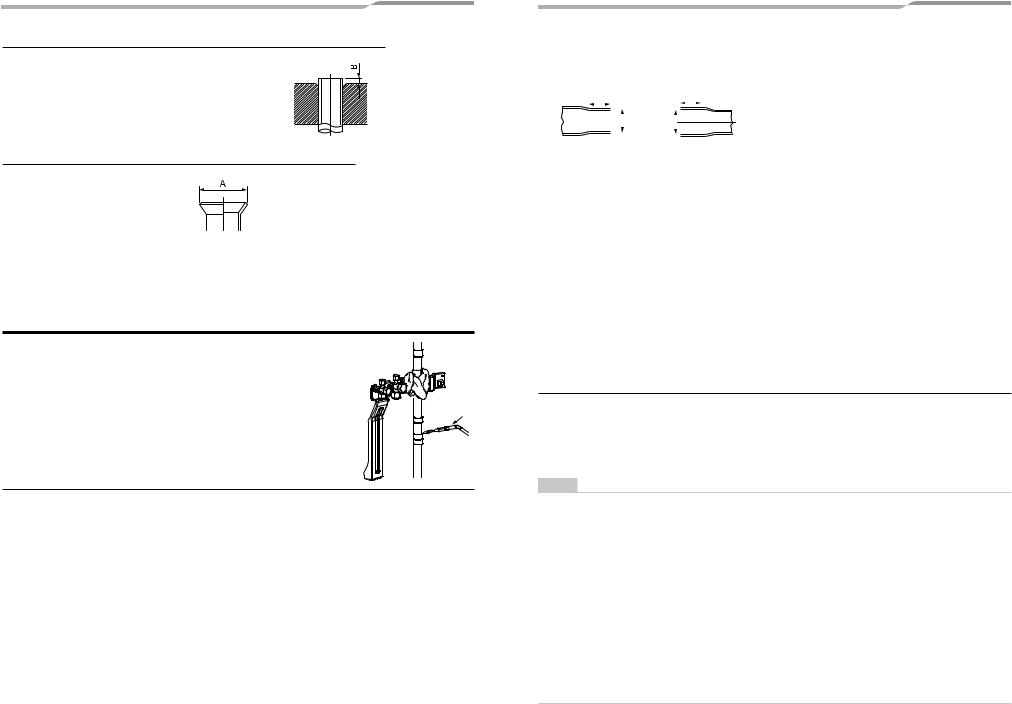
Extruding margin of copper pipe with flare machining: B (Unit: in (mm))
Copper pipe outer |
When using R410A |
When using |
dia. |
tool |
conventional tool |
3/8" (9.5) |
|
|
1/2"(12.7) |
0 - 0.02" |
0.04" - 0.06" |
5/8" (15.9) |
(0 - 0.5) |
(1.0 - 1.5) |
3/4" (19.1) |
|
|
|
|
|
Extruding margin of copper pipe with flare tools: A (Unit: in (mm))
Copper pipe outer |
A +0–0.02" (–0.4) |
dia. |
|
3/8" (9.5) |
0.52" (13.2) |
1/2"(12.7) |
0.65" (16.6) |
5/8" (15.9) |
0.78" (19.7) |
3/4" (19.1) |
0.94" (24.0) |
*When using the conventional flare tool, to connect R410A pipes with flaring, make a margin approx.
0.02" (0.5 mm) longer than that of an R22 pipe so that the flare size matches the one specified. It is convenient to use a copper pipe gauge for size adjustment of the extruding margin.
 CAUTION
Wrap the ball valve in a wet cloth to keep it cool and prevent the heat from the torch from damaging it when connecting the pipe to the ball valve on the gas line.

 Cloth
Cloth
Torch
17-EN
– 9 –
Coupling size of brazed pipe
|
|
|
|
|
Connected section |
|
|
|
|
|
|
|
|
|
|
|
|
|
|
||||||||
|
External size |
|
|
Internal size |
|
|
|
|
|
|
|
|
|
|
|||||||||||||
|
|
|
|
K |
|
|
|
|
|
|
G |
|
|
|
|
|
|
|
|
|
|
|
|||||
|
|
|
|
|
|
|
|
|
|
|
|
|
|
|
|
|
|
|
|
|
|
|
|
|
|
|
|
|
|
|
|
|
|
ØC |
|
|
ØF |
|
|
|
|
|
|
|
|
|
|
|
|
|
|
|
|
|
|
|
|
|
|
|
|
|
|
|
|
|
|
|
|
|
|
|
|
|
|
|
|
|
|
|
|
|
|
|
|
|
|
|
|
|
|
|
|
|
|
|
|
|
|
|
|
|
|
|
|
|
|
|
|
|
|
Standard |
|
|
|
|
|
|
|
|
|
|
|
|
|
|
Connected section |
|
|
|
|
Min. |
|||||||
|
|
|
External size |
|
|
|
Internal size |
|
|
|
|
|
|
||||||||||||||
outer dia. |
|
|
|
|
|
|
Min. depth of |
|
|
thickness |
|||||||||||||||||
|
|
|
|
|
|
Standard outer dia. |
|
|
|
|
|||||||||||||||||
of connected |
|
|
|
|
|
|
|
|
|
insertion |
|
Oval value |
of |
||||||||||||||
copper pipe |
|
|
|
|
(Allowable difference) |
|
|
|
|
|
|
|
|
coupling |
|||||||||||||
|
|
|
|
|
|
|
C |
|
|
|
|
|
|
|
|
F |
|
|
K |
G |
|
|
|
|
|||
in |
mm |
|
|
|
in |
mm |
|
|
|
in |
|
mm |
in |
mm |
in |
mm |
in |
mm |
in |
mm |
|||||||
Ø1/4 |
6.35 |
1/4"(±0.0012) |
|
6.35(±0.03) |
0.25" (−+00..00080016) |
6.45 (−+00..0204) |
0.28 |
7 |
0.24 |
6 |
0.0024" or less |
0.06 or less |
0.020" |
0.50 |
|||||||||||||
Ø3/8 |
9.52 |
3/8"(±0.0012) |
|
9.52(±0.03) |
0.38" (−+00..00080016) |
9.62 (−+00..0204) |
0.31 |
8 |
0.28 |
7 |
0.0031" or less |
0.08 or less |
0.024" |
0.60 |
|||||||||||||
Ø1/2 |
12.7 |
1/2"(±0.0012) |
|
12.70(±0.03) |
0.5" (−+00..00080016) |
12.81 (−+00..0204) |
0.35 |
9 |
0.31 |
8 |
0.0039" or less |
0.10 or less |
0.028" |
0.70 |
|||||||||||||
Ø5/8 |
15.88 |
5/8"(±0.0012) |
|
15.88(±0.03) |
0.63" (−+00..00080016) |
16.00 (−+00..0204) |
0.35 |
9 |
0.31 |
8 |
0.0051" or less |
0.13 or less |
0.031" |
0.80 |
|||||||||||||
Ø3/4 |
19.05 |
3/4"(±0.0012) |
|
19.05(±0.03) |
0.76" (−+00..00120012) |
19.19 (−+00..0303) |
0.43 |
11 |
0.39 |
10 |
0.0059" or less |
0.15 or less |
0.031" |
0.80 |
|||||||||||||
Ø7/8 |
22.2 |
7/8"(±0.0012) |
|
22.22(±0.03) |
0.88" (−+00..00120012) |
23.36 (−+00..0303) |
0.43 |
11 |
0.39 |
10 |
0.0063" or less |
0.16 or less |
0.032" |
0.82 |
|||||||||||||
Ø1-1/8 |
28.58 |
1-1/8"(±0.0012) |
28.58(±0.04) |
1.13" (−+00..00080024) |
28.75 (−+00..0206) |
0.51 |
13 |
0.47 |
12 |
0.0079" or less |
0.20 or less |
0.039" |
1.00 |
||||||||||||||
Ø1-3/8 |
34.92 |
1-3/8"(±0.0012) |
34.90(±0.04) |
1.38" (−+00..00160016) |
35.11 (−+00..0404) |
0.55 |
14 |
0.51 |
13 |
0.0098" or less |
0.25 or less |
0.047" |
1.20 |
||||||||||||||
Ø1-5/8 |
41.28 |
1-5/8"(±0.0012) |
41.28(±0.05) |
1.63" (−+00..00080031) |
42.28 (−+00..0208) |
0.59 |
15 |
0.55 |
14 |
0.0110" or less |
0.28 or less |
0.053" |
1.35 |
||||||||||||||
■ Selection of pipe size
Capacity code of indoor and outdoor units
Selection of pipe material
•For the indoor unit, the capacity code is decided at each capacity type. (Table 1)
•The capacity codes of the outdoor units are decided at each capacity type. The maximum number of connectable indoor units and the total value of capacity codes of the indoor units are also decided. (Table 2)
NOTE
Compared with the capacity code of the outdoor unit, the total value of capacity codes of the connectable indoor units differs based on the height difference between the indoor units.
When the height difference between the indoor units is 49 ft (15 m) or less
Total indoor capacity code must be between 80% and 135% of the capacity of the outdoor unit.
When the height difference between the indoor units is over 49 ft (15 m)
Total indoor capacity code must be between 80% and 105% of the capacity of the outdoor unit.
•If MMU-AP0072H2UL-1 or MMU-AP0122H2UL is included in the system, total indoor capacity code must be between 80% and 100% of outdoor unit capacity.
•If MMD-AP BH is included in the system, total indoor capacity code must be,
•when the height difference between the indoor units is over 49 ft (15 m): between 80% and 105%
•when the height difference between the indoor units is 49 ft (15 m) or less: between 80% and 120%
*If the system configure only the limited indoor unit type and limited number of connection indoor unit, total indoor capacity code up to 150% of the outdoor capacity code is available when the height difference between the indoor units is 49 ft (15 m) or less.
•If the minimum capacity of the connected indoor units is to be more than 50% and less than 80%, there are limiting conditions.
For more information, please refer to the engineering data book.
18-EN
 Loading...