


 Loading...
TOSHIBA Thermal Printer
B-SX6T/SX8T SERIES
 System Mode Manual
Document No. EO13-33002
Original Mar., 2006
(Revised )
PRINTED IN JAPAN
|
|
|
EO13-33002 |
|
|
|
(Revision Date: Jul. 24, 2008) |
|
|
TABLE OF CONTENTS |
|
|
|
|
Page |
1. INTRODUCTION----------------------------------------------------------------------------------------------------- |
1- 1 |
||
1.1 |
Key Operation Flow ---------------------------------------------------------------------------------------------- |
1- 1 |
|
1.2 |
Operation Panel --------------------------------------------------------------------------------------------------- |
1- 2 |
|
2. SYSTEM MODE ----------------------------------------------------------------------------------------------------- |
2- 1 |
||
2.1 |
Self-diagnostic Test ---------------------------------------------------------------------------------------------- |
2- 3 |
|
2.1.1 |
Printing Mode Selection ----------------------------------------------------------------------------------------- |
2- 4 |
|
2.1.2 |
Dispensing Mode Selection ------------------------------------------------------------------------------------ |
2- 4 |
|
2.1.3 |
Maintenance Counter/Parameter Settings Printing Out ------------------------------------------------- |
2- 5 |
|
2.1.4 |
Self-Diagnostic Test and Result Print Out ----------------------------------------------------------------- |
2-11 |
|
2.1.5 |
Print Head Element Check ------------------------------------------------------------------------------------ |
2-17 |
|
2.2 |
Parameter Setting------------------------------------------------------------------------------------------------ |
2-18 |
|
2.2.1 |
Character Code Selection ------------------------------------------------------------------------------------- |
2-19 |
|
2.2.2 |
Character Zero Selection -------------------------------------------------------------------------------------- |
2-20 |
|
2.2.3 |
Baud Rate Selection -------------------------------------------------------------------------------------------- |
2-20 |
|
2.2.4 |
Data Length Selection ------------------------------------------------------------------------------------------ |
2-21 |
|
2.2.5 |
Stop Bit Length Selection -------------------------------------------------------------------------------------- |
2-21 |
|
2.2.6 |
Parity Selection--------------------------------------------------------------------------------------------------- |
2-22 |
|
2.2.7 |
Flow Control Code Selection---------------------------------------------------------------------------------- |
2-22 |
|
2.2.8 |
LCD Language Selection -------------------------------------------------------------------------------------- |
2-23 |
|
2.2.9 |
Auto Forward Wait Selection---------------------------------------------------------------------------------- |
2-23 |
|
2.2.10 |
Head Up Cut Selection ----------------------------------------------------------------------------------------- |
2-24 |
|
2.2.11 |
Ribbon Save Function Selection ----------------------------------------------------------------------------- |
2-24 |
|
2.2.12 |
Control Code Selection----------------------------------------------------------------------------------------- |
2-25 |
|
2.2.13 |
Ribbon Type Selection ----------------------------------------------------------------------------------------- |
2-26 |
|
2.2.14 |
Strip Wait Status Selection ------------------------------------------------------------------------------------ |
2-26 |
|
2.2.15 |
FEED Key Function Selection -------------------------------------------------------------------------------- |
2-27 |
|
2.2.16 |
KANJI Code Selection ------------------------------------------------------------------------------------------ |
2-27 |
|
2.2.17 |
EURO Code Selection------------------------------------------------------------------------------------------ |
2-27 |
|
2.2.18 |
Auto Print Head Check Selection ---------------------------------------------------------------------------- |
2-28 |
|
2.2.19 |
Centronics Interface ACK/BUSY Timing Selection ------------------------------------------------------ |
2-28 |
|
2.2.20 |
Web Printer Function Selection ------------------------------------------------------------------------------ |
2-29 |
|
2.2.21 |
Media Sensor Selection ---------------------------------------------------------------------------------------- |
2-29 |
|
2.2.22 |
Input Prime Selection ------------------------------------------------------------------------------------------- |
2-30 |
|
2.2.23 |
Expansion I/O Interface Type Selection-------------------------------------------------------------------- |
2-30 |
|
2.2.24 |
Plug & Play Selection------------------------------------------------------------------------------------------- |
2-31 |
|
2.2.25 |
Label End/Ribbon End Selection ---------------------------------------------------------------------------- |
2-31 |
|
2.2.26 |
Pre-Strip Selection----------------------------------------------------------------------------------------------- |
2-33 |
|
2.2.27 |
Reverse Feed Speed Selection ------------------------------------------------------------------------------ |
2-33 |
|
2.2.28 |
Maxi Code Specification Selection -------------------------------------------------------------------------- |
2-33 |
|
2.2.29 |
Strip Motor Torque Selection --------------------------------------------------------------------------------- |
2-34 |
|
2.2.30 |
Stabilizer Function Selection---------------------------------------------------------------------------------- |
2-34 |
|
EO13-33002
(Revision Date: Jul 24, 2008)
|
|
|
Page |
2.3 Printer Parameter Fine Adjustment ----------------------------------------------------------------- |
2-35 |
||
2.3.1 Feed Amount Fine Adjustment ------------------------------------------------------------------------------- |
2-37 |
||
2.3.2 Cut/Strip Position Fine Adjustment -------------------------------------------------------------------------- |
2-38 |
||
2.3.3 Reverse Feed Amount Fine Adjustment ------------------------------------------------------------------- |
2-41 |
||
2.3.4 X Coordinate Fine Adjustment-------------------------------------------------------------------------------- |
2-42 |
||
2.3.5 Print Tone Fine Adjustment (Thermal Transfer/Thermal Direct Print) ------------------------------ |
2-44 |
||
2.3.6 Ribbon Motor Voltage Fine Adjustment (Feed/Take-up Motor) -------------------------------------- |
2-45 |
||
2.3.7 Threshold Manual Fine Adjustment (Black Mark/Feed Gap Sensor) ------------------------------- |
2-46 |
||
2.4 |
Test Print------------------------------------------------------------------------------------------------------------ |
2-47 |
|
2.4.1 Specifying the Print Condition for the Test Print --------------------------------------------------------- |
2-49 |
||
2.4.2 Test Print Pattern Selection ----------------------------------------------------------------------------------- |
2-52 |
||
2.4.3 Slant Line (1 dot)------------------------------------------------------------------------------------------------- |
2-53 |
||
2.4.4 Slant Line (3 dots) ----------------------------------------------------------------------------------------------- |
2-54 |
||
2.4.5 |
Characters--------------------------------------------------------------------------------------------------------- |
2-55 |
|
2.4.6 |
Barcode ------------------------------------------------------------------------------------------------------------ |
2-55 |
|
2.4.7 |
Non-Printing------------------------------------------------------------------------------------------------------- |
2-56 |
|
2.4.8 |
Factory Test------------------------------------------------------------------------------------------------------- |
2-56 |
|
2.4.9 |
Auto Print ---------------------------------------------------------------------------------------------------------- |
2-57 |
|
2.5 |
Sensor Adjustment ---------------------------------------------------------------------------------------------- |
2-58 |
|
2.5.1 |
Sensor Status Display ------------------------------------------------------------------------------------------ |
2-59 |
|
2.5.2 Black Mark Sensor Adjustment------------------------------------------------------------------------------- |
2-59 |
||
2.5.3 Feed Gap Sensor Adjustment -------------------------------------------------------------------------------- |
2-60 |
||
2.5.4 Black Mark Sensor and Feed Gap Sensor Adjustment (Paper End Level)------------------------ |
2-60 |
||
2.6 |
RAM Clear ---------------------------------------------------------------------------------------------------------- |
2-61 |
|
2.6.1 RAM Clear Menu Selection ----------------------------------------------------------------------------------- |
2-62 |
||
2.6.2 |
No RAM Clear ---------------------------------------------------------------------------------------------------- |
2-62 |
|
2.6.3 |
Maintenance Counter Clear ----------------------------------------------------------------------------------- |
2-62 |
|
2.6.4 |
Printer Parameter Clear ---------------------------------------------------------------------------------------- |
2-63 |
|
2.7 |
IP Address Setting----------------------------------------------------------------------------------------------- |
2-66 |
|
2.7.1 Printer IP Address, Gateway IP Address, and Subnet Mask Settings ------------------------------ |
2-67 |
||
2.7.2 |
Socket Port Setting---------------------------------------------------------------------------------------------- |
2-68 |
|
2.7.3 DHCP and DHCP ID Settings -------------------------------------------------------------------------------- |
2-68 |
||
2.7.4 DHCP Host Name Setting ------------------------------------------------------------------------------------- |
2-69 |
||
2.8 |
BASIC Setting ----------------------------------------------------------------------------------------------------- |
2-70 |
|
2.8.1 Basic Specification Selection Mode ------------------------------------------------------------------------- |
2-71 |
||
2.8.2 |
Basic File Browser----------------------------------------------------------------------------------------------- |
2-71 |
|
2.8.3 Basic Trace Selection Mode ---------------------------------------------------------------------------------- |
2-71 |
||
2.8.4 Basic Expansion Mode (Execution of Basic Program)-------------------------------------------------- |
2-72 |
||
2.9 |
RFID Module Setting -------------------------------------------------------------------------------------------- |
2-73 |
|
2.9.1 |
RFID Read Test-------------------------------------------------------------------------------------------------- |
2-74 |
|
2.9.2 RFID Module Type Selection --------------------------------------------------------------------------------- |
2-75 |
||
2.9.3 RFID Tag Type Selection -------------------------------------------------------------------------------------- |
2-76 |
||
2.9.4 RFID Error Tag Delection-------------------------------------------------------------------------------------- |
2-76 |
||
2.9.5 Maximum Number of RFID Issue Retries------------------------------------------------------------------ |
2-77 |
||
2.9.6 Maximum Number of RFID Read Retries------------------------------------------------------------------ |
2-78 |
||
2.9.7 RFID Read Retry Time-out ------------------------------------------------------------------------------------ |
2-79 |
||
EO13-33002
(Revision Date: Jul 24, 2008)
|
|
Page |
2.9.8 |
Maximum Number of RFID Write Retries ------------------------------------------------------------------ |
2-80 |
2.9.9 |
RFIDWritre Retry Time-out ------------------------------------------------------------------------------------ |
2-81 |
2.9.10 |
RFID Adjustment for Retry ------------------------------------------------------------------------------------ |
2-82 |
2.9.11 |
RFID Wireless Power Level Setting------------------------------------------------------------------------- |
2-83 |
2.9.12 |
RFID AGC Threshold ------------------------------------------------------------------------------------------- |
2-83 |
2.9.13 |
RFID Module Q Value Setting -------------------------------------------------------------------------------- |
2-84 |
2.9.14 |
AGC Threshold for Data Write Setting---------------------------------------------------------------------- |
2-85 |
2.9.15 |
AGC Threshold Lower Limit for Retry Setting ------------------------------------------------------------ |
2-86 |
3. ON LINE MODE ------------------------------------------------------------------------------------------ |
3- 1 |
|
3.1 |
Automatic Threshold Setting --------------------------------------------------------------------------------- |
3- 4 |
3.2 |
Reset Operation --------------------------------------------------------------------------------------------------- |
3- 5 |
3.3 |
Dump Mode --------------------------------------------------------------------------------------------------------- |
3- 6 |
3.4 |
BASIC Expansion Mode ---------------------------------------------------------------------------------------- |
3- 8 |
3.5 |
Automatic Calibration Setting -------------------------------------------------------------------------------- |
3- 9 |
3.6 |
LAN Enable/Disable Setting ---------------------------------------------------------------------------------- |
3-11 |
3.7 |
Real Time Clock (RTC) Setting ------------------------------------------------------------------------------ |
3-12 |
4. PROGRAM DOWN LOAD ----------------------------------------------------------------------------- |
4- 1 |
||
4.1 |
Outline of Features ----------------------------------------------------------------------------------------------- |
4- 1 |
|
4.2 |
Download Program Installation ------------------------------------------------------------------------------ |
4- 1 |
|
4.2.1 |
System Requirements ------------------------------------------------------------------------------------------- |
4- 1 |
|
4.2.2 |
Setup----------------------------------------------------------------------------------------------------------------- |
4- 2 |
|
4.3 |
Firmware Download ---------------------------------------------------------------------------------------------- |
4- 2 |
|
5. RFID ANALYZE TOOL --------------------------------------------------------------------------------- |
5- 1 |
||
5.1 |
System Requirement--------------------------------------------------------------------------------------------- |
5- 1 |
|
5.2 |
Set up ----------------------------------------------------------------------------------------------------------------- |
5- 2 |
|
5.3 |
Application Functions ------------------------------------------------------------------------------------------- |
5- 3 |
|
5.3.1 |
Main Menu---------------------------------------------------------------------------------------------------------- |
5- 3 |
|
5.3.2 |
File Menu ----------------------------------------------------------------------------------------------------------- |
5- 4 |
|
5.3.3 |
Tool Menu ---------------------------------------------------------------------------------------------------------- |
5- 7 |
|
5.3.4 |
Help Menu --------------------------------------------------------------------------------------------------------- |
5-12 |
|
5.4 |
Operating Procedure-------------------------------------------------------------------------------------------- |
5-13 |
|
CAUTION!
1.This manual may not be copied in whole or in part without prior written permission of TOSHIBA TEC.
2.The contents of this manual may be changed without notification.
Copyright © 2006
by TOSHIBA TEC CORPORATION All Rights Reserved
570 Ohito, Izunokuni-shi, Shizuoka-ken, JAPAN
1. INTRODUCTION
EO13-33002
(Revision Date: Jul. 24, 2008)
1.1 Key Operation Flow
1. INTRODUCTION
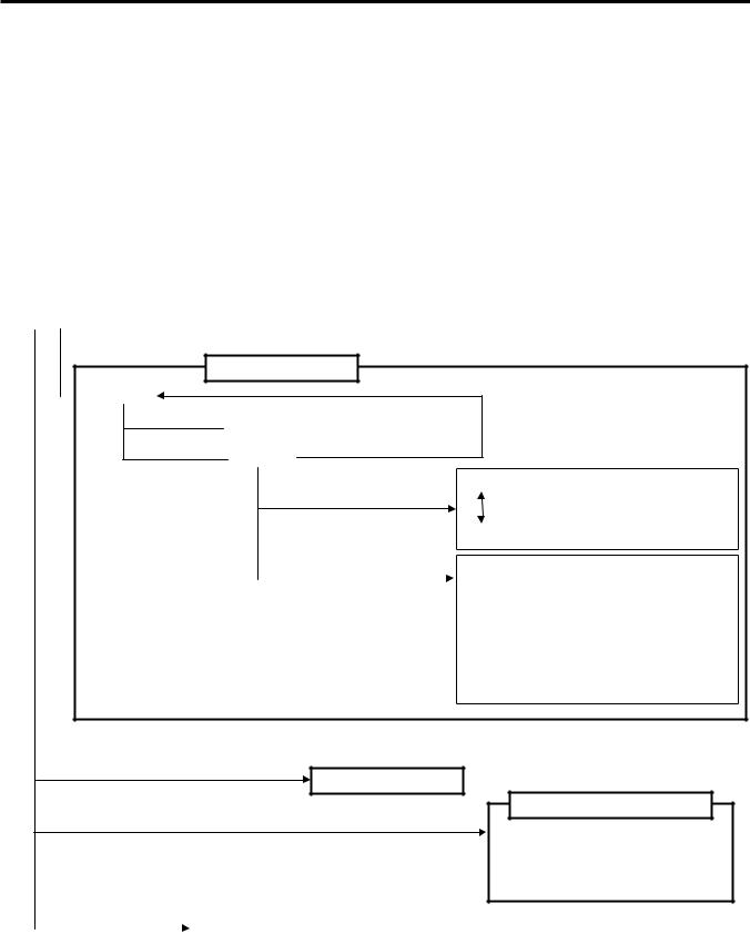
This document describes key operations using the keys and LCD display on the printer that you can operate on a printer alone. Key operations are performed in the following four printer setting modes:
•Online mode where a pause, reset, automatic threshold setting, etc. are performed.
•Download mode where a firmware downloading is performed.
•System mode for service personnel where a self-diagnosis, printer parameter settings, RAM clear, IP address setting etc. are performed.
•System mode for end user where a self-diagnosis, printer parameter settings, fine adjustment, etc., which are same functions as those in System mode for service personnel, are performed.
NOTE: This document uses the B-SX8T for examples of the display.
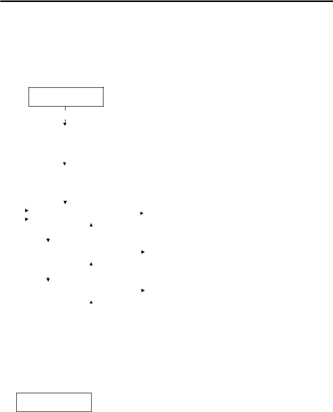
1.1 Key Operation Flow
Power OFF
Turn the power on.
Online mode
 Online
[FEED] key
[PAUSE] key
 Feeds one label.
[RESTART] key
 Pause
Pause
Hold down the [PAUSE] key |
Feed gap sensor automatic threshold setting |
for a few seconds. |
[FEED] key or [RESTART] key |
|
Hold down the [RESTART] key |
Black mark sensor threshold setting |
|
|
for a few seconds. |
• Reset |
|
• Parameter Setting |
|
• Fine adjustment |
|
• Dump mode |
|
• Expand mode (Basic expansion mode) |
|
• Automatic calibration mode |
|
• LAN Enable/Disable |
|
• RTC Setting |
While holding down the [FEED],
[RESTART], and [PAUSE] keys, turn the power on.
Download mode
While holding down the [FEED] and [RESTART] keys, turn the power on.
While holding down the |
|
System mode for service personnel |
|
||
|
|
||||
|
|
|
|||
• Self-test |
|||||
[FEED] and [PAUSE] |
|||||
• Parameter setting |
|||||
keys, turn the power on. |
|||||
• Fine adjustment |
|||||
|
|
||||
|
|
• Test print |
|||
|
|
||||
|
|
• Sensor adjustment |
|||
|
|
• RAM clear |
|||
|
|
• IP Address setting |
|||
|
|
• Basic setting |
|||
|
|
• For factory |
|||
|
|
• RFID Module Setting |
|||
|
|
|
|
|
|
System mode for end users
• Self-test
•Parameter setting
•Fine adjustment
•Test print
1- 1
1. INTRODUCTION
EO13-33002
1.2 Operation Panel
1.2 Operation Panel
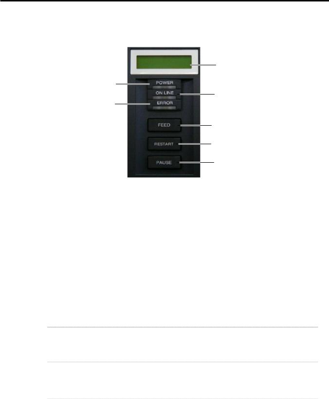
The figure below illustrates the Operation Panel and key functions.
POWER LED (Green)
ERROR LED (Red)
LCD Message
Display
ON LINE LED (Green)
[FEED] key
[RESTART] key
[PAUSE] key
The LCD Message Display is a 16-character x 2-line display, which shows messages in alphanumeric characters and symbols to indicate the printer’s status. .
There are three LEDs on the Operation Panel.
LED |
Illuminates when… |
POWER |
The printer is turned on. |
ON LINE |
The printer is ready to print. |
ERROR |
The printer is in an error state. |
The [FEED], [RESTART] and [PAUSE] keys function as described below.
FEED |
Feeds or ejects one media. |
|
Adjusts media to a proper position if the media is not properly positioned by feeding |
|
one or two blank media before printing. |
|
Prints data in the image buffer on one media according to the system mode setting. |
|
In system mode, this key is used to select various parameters or to set a fine |
|
adjustment value in the negative direction (-). |
RESTART |
Resumes printing when the printer is in a pause state or an error state. |
|
Restores the same state as when the power is turned off and on again. |
|
In system mode, this key is used to select various parameters or to set a fine |
|
adjustment value in the positive direction (+). |
|
|
PAUSE |
Stops printing temporarily. |
|
Programs threshold values. |
|
In system mode, this key is used as an enter key. |
1- 2
2. SYSTEM MODE
2. SYSTEM MODE
EO13-33002
2. SYSTEM MODE
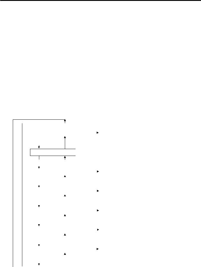
System mode consists of ten main menus: Self-diagnostic test, Parameter setting, Printer parameter fine adjustment, Test print, Sensor adjustment, RAM clear, IP address setting, Basic setting, and Factory mode.
Each menu is used for the following purposes:
•To check and print the system status, the Maintenance Counter, and the Print Head Element.
•To set the parameters for the communication with the host computer, and the printer functions such as the language for LCD message, Feed key function, etc.
•To make fine adjustment related to the media issue.
•To perform a test print for checking print quality.
•To check the status of the sensors and to set the threshold of the media sensor for pre-printed media.
•To perform a Maintenance Counter clear and Parameter clear.
•To set the IP address
•To set the Basic setting
•To perform the factory mode
To enter System mode, turn on the printer while pressing the [FEED] and [PAUSE] keys at the same time. Hold both keys until “<1>DIAG. Vx.x” message appears on the display.
|
|
|
|
[RESTART] |
|
|
|
This is the start of the Self-Diagnostic Test |
|
|
|
|
|
|
|
|
|
|
|
|
<1>DIAG. Vx.x |
|
[PAUSE] |
|
|||||
|
|
|
menu. → Section 2.1 |
||||||
|
|
|
|
|
|
|
|
|
|
|
[FEED] |
|
|
|
|
|
|
||
<2>PARAMETER SET  [PAUSE]
[FEED] [RESTART]
|
|
|
|
|
|
|
|
|
|
|
|
|
|
|
|
|
|
|
|
|
|
|
|
|
|
|
|
|
|
|
|
|
<3>ADJUST SET |
|
|
[PAUSE] |
|
|
|||||||||
|
|
|
|
|
|||||||||||
|
|
|
|
|
|
|
|
|
|
|
|
|
|
|
|
|
|
|
|
|
|
|
|
|
|
|
|
|
|
|
|
|
[FEED] |
|
|
|
|
|
|
|
|
|
|
|
|
|
|
|
|
|
[RESTART] |
|
|
|
|
|
|
|
|||||
|
|
|
|
|
|
|
|
|
|
|
|
|
|||
|
|
|
|
|
|
|
|
|
|
|
|
|
|
|
|
|
<4>TEST PRINT |
|
|
[PAUSE] |
|
|
|||||||||
|
|
|
|
|
|||||||||||
|
|
|
|
|
|
|
|
|
|
|
|
|
|
|
|
|
|
|
|
|
|
|
|
|
|
|
|
|
|
|
|
|
[FEED] |
|
|
|
|
|
|
|
|
|
|
|
|
|
|
|
|
|
[RESTART] |
|
|
|
|
|
|
|
|||||
|
|
|
|
|
|
|
|
|
|
|
|
|
|||
|
|
|
|
|
|
|
|
|
|
|
|
|
|
|
|
|
<5>SENSOR ADJ. |
|
|
[PAUSE] |
|
|
|||||||||
|
|
|
|
|
|||||||||||
|
|
|
|
|
|
|
|
|
|
|
|
|
|
|
|
|
|
|
|
|
|
|
|
|
|
|
|
|
|
|
|
|
|
|
|
|
|
|
|
|
|
|
|
|
|
|
|
|
[FEED] |
|
|
|
[RESTART] |
|
|
|
|
|
|
|
|||
|
|
|
|
|
|
|
|
|
|
|
|
|
|
|
|
|
|
|
|
|
|
|
|
|
|
|
|
|
|
|
|
|
<6>RAM CLEAR |
|
|
|
[PAUSE] |
|
|
||||||||
|
|
|
|
|
|
||||||||||
|
|
|
|
|
|
|
|
|
|
|
|
|
|
|
|
|
|
|
|
|
|
|
|
|
|
|
|
|
|
|
|
|
|
|
|
|
|
|
|
|
|
|
|
|
|
|
|
|
[FEED] |
|
|
|
|
|
|
|
|
|
|
|
|
|
|
|
|
|
[RESTART] |
|
|
|
|
|
|
|
|||||
|
|
|
|
|
|
|
|
|
|
|
|
|
|||
|
|
|
|
|
|
|
|
|
|
|
|
|
|
|
|
|
<7>IP ADDRESS |
|
[PAUSE] |
|
|
|
|||||||||
|
|
|
|
|
|||||||||||
|
|
|
|
|
|
|
|
|
|
|
|
|
|
|
|
|
|
|
|
|
|
|
|
|
|
|
|
|
|
|
|
|
|
|
|
|
|
|
|
|
|
|
|
|
|
|
|
|
[FEED] |
|
|
|
|
|
|
|
|
|
|
|
|
|
|
|
|
|
[RESTART] |
|
|
|
|
|
|
|
|||||
|
|
|
|
|
|
|
|
|
|
|
|
|
|||
|
|
|
|
|
|
|
|
|
|
|
|
|
|
|
|
This is the start of the Parameter Setting menu. → Section 2.2
This is the start of the Printer Parameter Fine Adjustment menu. → Section 2.3
This is the start of the Test Print menu.
→ Section 2.4
This is the start of the Sensor Adjustment menu. → Section 2.5
This is the start of the RAM Clear menu.
→ Section 2.6
This is the start of the IP Address Setting menu. → Section 2.7
Continued on the next page.
2- 1

2. SYSTEM MODE
EO13-33002 (Revision Date: Jul. 24, 2008)
2. SYSTEM MODE
Continued from the previous page.
|
|
|
|
|
|
|
|
|
|
|
|
|
|
|
|
|
|
|
|
|
|
|
|
|
|
|
|
<8>BASIC |
|
|
|
[PAUSE] |
|
|
||||
|
|
|
|
|
|
|
||||||
|
|
|
|
|
|
|
|
|
|
|
|
|
|
|
|
|
|
|
|
|
|
|
|
|
|
|
|
|
|
|
|
|
|
|
|
|
|
|
|
|
[FEED] |
|
[RESTART] |
|
|
|
|
|
|||
|
|
|
|
|
|
|
|
|
|
|
|
|
|
|
|
|
|
|
|
|
|
|
|
|
|
|
|
<9>FOR FACTORY |
|
|
[PAUSE] |
|
|
|||||
|
|
|
|
|
|
|||||||
|
|
|
|
|
|
|
|
|
|
|
|
|
|
|
|
|
|
|
|
|
|
|
|
|
|
|
|
[FEED] |
|
[RESTART] |
|
|
|
|
|
|||
|
|
|
|
|
|
|
|
|
|
|
|
|
|
|
|
|
|
|
|
|
|
|
|
|
|
|
|
<10>RFID |
|
|
|
|
[PAUSE] |
|
|
|||
|
|
|
|
|
|
|
|
|||||
|
|
|
|
|
|
|
|
|
|
|
|
|
|
|
|
|
|
|
|
|
|
|
|
|
|
|
|
|
|
|
|
|
|
|
|
|
|
|
|
|
[FEED] |
|
|
|
|
|
|
|
|
||
|
|
|
|
|
|
|
|
|
|
|
|
|
|
|
|
|
|
|
|
|
|
|
|
|
|
|
|
|
|
|
|
|
|
|
|
|
|
|
This is the start of the Basic Setting menu.
→ Section 2.8
This is the start of the Factory Mode menu.
This is the RFID Module Setting menu.
→ Section 2.9
NOTES: 1. System Mode menu can be selected with the [RESTART] or [FEED] key.
2.Pressing the [PAUSE] key allows you to enter the sub menus of each System Mode menu. Flowcharts of each menu’s sub menus are provided on the following pages.
3.“x.x” of “DIAG. Vx.x” indicates firmware version and revision.
2- 2
2. SYSTEM MODE
EO13-33002
2.1 Self-diagnostic Test
2.1 Self-diagnostic Test
Outline of Self-diagnostic Test
In the Self-diagnostic test mode, the printer automatically checks and prints out the printer system information such as the sensor status or interface, and the maintenance counter. Also it performs a print head broken element check.
The Self-diagnostic test contains the following sub menus:
<1>DIAG. Vx.x
[PAUSE]
|
|
|
|
<1>DIAG. Vx.x |
|
|
|
|
|
|
|
|
|
Selection of the printing mode. |
||||||||||
|
|
|
|
PRT TYPE TRANSFR |
|
|
|
|
|
|
|
|
|
|||||||||||
|
|
|
|
|
|
|
|
|
|
|
|
|
|
|||||||||||
|
|
|
|
|
|
|
|
|
|
|
|
|
|
|
|
|
|
|
|
|
|
|
|
|
|
|
|
|
|
|
|
|
|
|
|
|
|
|
|
|
|
|
|
|
|
|
|
|
|
|
|
|
|
|
|
|
[PAUSE] |
|
|
|
|
|
|
|
|
|
|
|
|
|||||
|
|
|
|
|
|
|
|
|
|
|
|
|
|
|
|
|
|
|
|
|
|
|
|
|
|
|
|
|
|
|
|
|
|
|
|
|
|
|
|
||||||||||
|
|
|
|
<1>DIAG. Vx.x |
|
|
|
|
|
|
|
|
|
Selection of the dispensing mode. |
||||||||||
|
|
|
|
TYPE[S] NO CUT |
|
|
|
|
|
|
|
|
|
|||||||||||
|
|
|
|
|
|
|
|
|
|
|
|
|
|
|||||||||||
|
|
|
|
|
|
|
|
|
|
|
|
|
|
|
|
|
|
|
||||||
|
|
|
|
|
|
|
|
|
|
|
|
|
|
|
|
|
|
|
|
|
|
|
|
|
|
|
|
|
|
|
|
[PAUSE] |
|
|
|
|
|
|
|
|
|
|
|
||||||
|
|
|
|
|
|
|
|
|
|
|
|
|
|
|
|
|
|
|
|
|
|
|
|
|
|
|
|
|
|
|
|
|
|
|
|
|
|
|
|
|
|
|
|
|
|
|
|
|
|
|
|
|
|
<1>DIAG. Vx.x |
|
|
|
|
|
|
|
|
|
|
||||||||||
|
|
|
|
|
[PAUSE] |
|
|
|
|
Prints out the Maintenance Counter /Parameter Settings. |
||||||||||||||
|
|
|
|
|
|
|
|
|
||||||||||||||||
|
|
|
|
MAINTENANCE CONT. |
|
|
|
|
|
|||||||||||||||
|
|
|
|
|
|
|
|
|
|
|
|
|
|
|||||||||||
|
|
|
|
|
|
|
|
|
|
|
|
|||||||||||||
|
|
|
|
|
|
|
|
|
|
|
|
|
|
|
|
|
|
|
|
|
|
|||
|
|
|
|
|
|
|
|
|
|
|
|
|
|
|
|
|
|
|
|
|
|
|
|
|
|
|
|
|
|
|
|
|
|
|
|
|
|
|
|
|
|
|
|
|
|
|
|
|
|
|
|
|
|
|
|
[FEED] |
|
|
|
|
[RESTART] |
|
|
|
|
|
||||||||
|
|
|
|
|
|
|
|
|
|
|
|
|
|
|
|
|
|
|
|
|||||
|
|
|
|
<1>DIAG. Vx.x |
|
|
|
|
|
|
|
|
|
Performs a Self-Diagnostic Test, and prints out the result. |
||||||||||
|
|
|
|
|
|
[PAUSE] |
|
|
||||||||||||||||
|
|
|
|
AUTO DIAGNOSTIC |
|
|
|
|
||||||||||||||||
|
|
|
|
|
|
|
|
|
|
|
|
|
|
|||||||||||
|
|
|
|
|
|
|
|
|
|
|
|
|
|
|
|
|
|
|
|
|
|
|
|
|
|
|
|
|
|
|
|
|
|
|
|
|
|
|
|
|
|
|
|
|
|
|
|
|
|
|
|
|
|
|
|
[FEED] |
|
|
|
[RESTART] |
|
|
|
|
|
|||||||||
|
|
|
|
|
|
|
|
|
|
|
|
|
|
|
|
|
|
|
|
|||||
|
|
|
|
<1>DIAG. Vx.x |
|
|
|
|
|
|
|
|
|
Checks to see if there is any problem with the print head. |
||||||||||
|
|
|
|
|
[PAUSE] |
|
|
|
||||||||||||||||
|
|
|
|
HEAD CHECK |
|
|
|
|||||||||||||||||
|
|
|
|
|
|
|
|
|
|
|
|
|
|
|||||||||||
|
|
|
|
|
|
|
|
|
|
|
|
|
|
|
|
|
|
|
|
|
|
|
|
|
|
|
|
|
|
|
[FEED] |
|
|
|
|
|
|
|
|
|
|
|
|
|
|
|
|
|
|
|
|
|
|
|
|
|
|
|
|
[RESTART] |
|
|
|
|
|
|
||||||||
|
|
|
|
|
|
|
|
|
|
|
|
|
|
|
|
|
||||||||
|
|
|
|
|
|
|
|
|
|
|
|
|
|
|
|
|
|
|
|
|
|
|
|
|
NOTE: Use the [FEED] or [RESTART] key to select a desired option.
How to Enter Self-diagnostic Test Mode
Turn on the printer while pressing the [FEED] and [PAUSE] keys at the same time. Hold both keys until the “<1>DIAG. Vx.x” message appears in the display.
<1>DIAG. Vx.x
2- 3

2. SYSTEM MODE
EO13-33002
2.1 Self-diagnostic Test
2.1.1 Printing Mode Selection
While “PRT TYPE TRANSFR” is displayed on the LCD, press the [PAUSE] key. The type of printing mode can be selected:
“TRANSFR” (Thermal transfer) or “DIRECT” (Thermal direct).
After selecting the printing mode to be used, press the [PAUSE] key.
|
|
|
|
|
|
|
|
|
|
|
|
|
|
<1>DIAG. Vx.x |
Thermal transfer: When transparent ribbon is used. |
|
|
|
|
|
|
PRT TYPE TRANSFR |
|
|
[RESTART] |
|
|
||||
|
|
|
|
||||
|
|
||||||
|
|
|
|
|
|
|
|
|
|
|
|
|
|
<1>DIAG. Vx.x |
Thermal transfer: When non-transparent ribbon is used. |
|
|
|
|
|
|
PRT TYPE NO TRAN |
|
|
|
[FEED] |
|
|
|
||
|
|
|
|
|
|
||
|
|
|
|
|
|
<1>DIAG. Vx.x |
Thermal direct: When thermal paper is used. |
|
|
|
|
|
|
PRT TYPE DIRECT |
|
|
|
|
|
|
|
|
|
|
|
|
|
|
|
|
|
NOTE: When using the ribbon, be sure to select “Thermal Transfer”. When using the thermal media, be sure to select the “Thermal Direct”.
2.1.2 Dispensing Mode Selection
When “TYPE[S] NO CUT” is displayed, press the [PAUSE] key. The type of dispensing mode can be selected:
“[S] NO CUT” (Batch issue) or “[C] WITH CUT” (Cut issue)
After selecting the dispensing mode to be used, press the [PAUSE] key.
|
|
|
|
|
|
|
|
|
|
|
|
|
<1>DIAG. Vx.x |
|
|
|
|
|
|
TYPE[S] NO CUT |
|
[RESTART] |
|
||||
|
|
|
|
|
|
|
|
|
|
|
|
|
<1>DIAG. Vx.x |
|
|
|
|
|
|
TYPE[C] WITH CUT |
|
|
|
|
|
|
|
|
|
|
|
|
|
|
|
|
[FEED] |
|
|
||
|
|
|
|
|
|
|
|
|
|
|
|
|
|
[S] NO CUT (Batch issue): To issue media in batch mode.
[C] WITH CUT (Cut issue): When an optional cutter module is installed.
NOTE: When using the cutter module, be sure to select “[C] WITH CUT”. When the cutter module is not installed, be sure to select “[S] NO CUT”.
2- 4
2. SYSTEM MODE
EO13-33002
2.1 Self-diagnostic Test
2.1.3 Maintenance Counter/Parameter Settings Print Out
When “MAINTENANCE CONT” is displayed, the printer is ready to print out the Maintenance Counter/Parameter Settings. Press the [PAUSE] key to start.
|
<1>DIAG. Vx.x |
|
|
|
|
|
|
|
<1>DIAG. Vx.x |
|
|
|
<1>DIAG. Vx.x |
||
|
|
|
|
[PAUSE] |
|
|
|
|
|
|
|||||
|
MAINTENANCE CONT |
|
|
|
|
CHECKING & PRINT |
|
|
|
|
|
||||
|
|
|
|
|
|
|
|
|
|
|
|||||
|
(1) |
|
|
|
|
|
|
|
|
|
|
|
|
|
|
• Print Sample |
|
TOTAL FEED |
|
|
1.1km |
[QM] |
|
||||||||
|
|
(2) |
|
FEED |
|
|
1.1km |
|
|
|
|
|
|||
|
|
(3) |
|
|
|
0.5km |
|
|
|
|
|
||||
|
|
(4) |
|
CUT |
|
|
96 |
|
|
|
|
|
|||
|
|
(5) |
|
HEAD U/D |
|
|
12320 |
|
|
|
|
|
|||
|
|
(6) |
|
RIBBON |
|
|
3h |
|
|
|
|
|
|||
|
|
(7) |
|
SOLENOID |
|
|
2h |
|
|
|
|
|
|||
|
|
(8) |
|
232C ERR |
|
|
255 |
|
|
|
|
|
|||
|
|
(9) |
|
SYSTEM ERR |
|
|
0 |
|
|
|
|
|
|||
|
|
(10) |
|
POWER FAIL |
|
|
0 |
|
|
|
|
|
|||
|
|
(11) |
|
[PC] |
|
|
[KEY] |
|
|
|
|
|
|||
|
|
|
FEED |
+2.0mm |
FEED |
|
+0.0mm |
|
|||||||
|
|
(12) |
|
CUT |
+0.0mm |
CUT |
|
+1.0mm |
|
||||||
|
|
(13) |
|
BACK |
+0.0mm |
BACK |
|
+0.0mm |
|
||||||
|
|
(14) |
|
TONE(T) |
+0 step |
TONE(T) |
|
+0 step |
|
||||||
|
|
(15) |
|
TONE (D) |
+0 step |
TONE(D) |
|
+0 step |
|
||||||
|
|
(16) |
|
RBN(FW) |
-10 |
RBN (FW) |
-8 |
|
|
|
|||||
|
|
(17) |
|
RBN (BK) |
+0 |
RBN (BK) |
+0 |
|
|
|
|||||
|
|
(18) |
|
X ADJ. |
+0.0mm |
|
|
|
|
|
|
||||
|
|
(19) |
|
THRESHOLD (R) |
1.0V |
|
|
|
|
|
|||||
|
|
(20) |
|
THRESHOLD (T) |
1.4V |
|
|
|
|
|
|||||
|
|
(21) |
|
FONT |
|
|
[PC-850] [0] |
|
|
|
|
|
|||
|
|
(22) |
|
SPEED |
|
|
[9600] |
|
|
|
|
|
|||
|
|
(23) |
|
DATA LENG. |
|
|
[8] |
|
|
|
|
|
|||
|
|
(24) |
|
STOP BIT |
|
|
[1] |
|
|
|
|
|
|||
|
|
(25) |
|
PARITY |
|
|
[EVEN] |
|
|
|
|
|
|||
|
|
(26) |
|
CONTROL |
|
|
[XON+READY AUTO] |
|
|||||||
|
|
(27) |
|
MESSAGE |
|
|
[ENGLISH] |
|
|
|
|
|
|||
|
|
(28) |
|
FORWARD WAIT |
[ON] +0.0mm |
|
|
|
|
|
|||||
|
|
(29) |
|
HEAD UP CUT |
|
|
[ON] |
|
|
|
|
|
|||
|
|
(30) |
|
RIBBON SAVE |
|
|
[ON:LABEL] |
|
|
|
|
|
|||
|
|
(31) |
|
CODE |
|
|
[AUTO] |
|
|
|
|
|
|||
|
|
(32) |
|
RIBBON |
|
|
[TRANS] |
|
|
|
|
|
|||
|
|
(33) |
|
PEEL OFF STATUS |
[ON] |
|
|
|
|
|
|||||
|
|
(34) |
|
FEED KEY |
|
|
[FEED] |
|
|
|
|
|
|||
|
|
(35) |
|
KANJI |
|
|
[TYPE1] |
|
|
|
|
|
|||
|
|
(36) |
|
EURO CODE |
|
|
[B0] |
|
|
|
|
|
|||
|
|
(37) |
|
AUTO HD CHK |
|
|
[OFF] |
|
|
|
|
|
|||
|
|
(38) |
|
ACK/BUSY |
|
|
[TYPE1] |
|
|
|
|
|
|||
|
|
(39) |
|
WEB PRINTER |
|
|
[OFF] |
|
|
|
|
|
|||
|
|
(40) |
|
SENSOR POSITION |
[CENTER] |
|
|
|
|
|
|||||
|
|
(41) |
|
INPUT PRIME |
|
|
[ON] |
|
|
|
|
|
|||
|
|
(42) |
|
EX. I/O MODE |
|
|
[TYPE1] |
|
|
|
|
|
|||
|
|
(43) |
|
PLUG & PLAY |
|
|
[OFF] |
|
|
|
|
|
|||
|
|
(44) |
|
LBL/RBN END |
|
|
[TYPE1] |
|
|
|
|
|
|||
|
|
(45) |
|
PRE PEEL OFF |
[ON] +0.0mm |
|
|
|
|
|
|||||
|
|
(46) |
|
BACK SPEED |
|
|
[STD] |
|
|
|
|
|
|||
|
|
(47) |
|
MAXI CODE SPEC. |
[TYPE1] |
|
|
|
|
|
|||||
|
|
(48) |
|
PEEL OFF TRQ |
[R3] |
|
|
|
|
|
|||||
|
|
|
|
------------------------------------------------------------------------------ |
|
||||||||||
|
|
|
|
||||||||||||
|
|
|
|
|
|||||||||||
2- 5

2. SYSTEM MODE
EO13-33002
(Revision Date: Jul. 24, 2008)
2.1 Self-diagnostic Test
(49) |
------------------------------------------------------------------------------- |
|||
STABILIZER |
[ON] |
|
||
(50) |
AUTO CALIB. |
[OFF] |
|
|
(51) |
LAN |
[ON SNMP ON] |
|
|
(52) |
PRTR IP ADDRESS |
[192.168.010.020] |
|
|
(53) |
GATE IP ADDRESS |
[000.000.000.000] |
|
|
(54) |
SUBNET MASK |
[255.255.255.000] |
|
|
(55) |
MAC ADDRESS |
[00-80-91-34-00-CC] |
||
(56) |
TTF AREA |
[1280KB] |
|
|
(57) |
EXT CHR AREA |
[ 256KB] |
|
|
(58) |
BASIC AREA |
[ 128KB] |
|
|
(59) |
PC SAVE AREA |
[ 128KB] |
|
|
(60) |
SOCKET PORT |
[OFF][08000] |
|
|
(61) |
BASIC |
[OFF] |
|
|
(62) |
BASIC TRACE |
[OFF] |
|
|
(63) |
DHCP |
[OFF] |
|
|
(64) |
DHCP ID |
[FFFFFFFFFFFFFFFFFFFF] |
||
(65) |
|
[FFFFFFFFFFFF] |
|
|
DHCP HOST NAME |
[ |
|
] |
|
(66) |
RTC BATT. CHK |
[ON] |
|
|
(67) |
RTC RENEWAL |
[PAGE] |
|
|
(68) |
RFID MODULE |
[U2] |
|
|
(69) |
RFID TAG TYPE |
[NONE |
] |
|
(70) |
RFID ERR CHECK |
[OFF] |
|
|
(71) |
RFID RETRY |
[ |
3] |
|
(72) |
RFID RD CYCLE |
[ |
5] [2.0sec] |
|
(73) |
RFID WT CYCLE |
[ |
5] [2.0sec] |
|
(74) |
RFID ADJ RETRY |
[+00mm] |
|
|
(75) |
RFID POWER LEV |
[ 18] |
|
|
(76) |
RFID AGC THR. |
[0] |
|
|
(77) |
RFID Q VAL |
[0] |
|
|
(78) |
RFID WT AGC |
[ |
0] |
|
(79) |
RFID WT AGC MIN |
[ |
0] |
|
(80) |
RFID WT OK TAGS |
|
0 |
|
(81) |
RFID VOID PRINT TAGS |
|
0 |
|
|
|
|
|
|
NOTE: Print conditions:
Print speed: 4”/sec., Sensor: No sensor, Printing mode: Thermal transfer/Direct thermal(*1), Media length: 240 mm, Issue mode: Batch printing
(*1) Depends on the printing mode setting.
2- 6

2. SYSTEM MODE
EO13-33002
(Revision Date: Jul. 24, 2008)
2.1 Self-diagnostic Test
• Descriptions of the Maintenance Counter
# |
Item |
Count Condition |
Range |
(1) |
Total media distance |
Counts when the feed motor is driven to feed, print or issue media. |
0.0 to 3200.0 km |
|
covered |
(Counted also during a reverse feed.) See NOTE 2. |
|
(2) |
Media distance |
Destination printed on the same line indicates one selected for a |
0.0 to 3200.0 km |
|
covered |
parameter clear. |
|
(3) |
Print distance |
Counts while printing. (Reverse feed is not counted.) See NOTE 3. |
0.0 to 200.0 km |
(4) |
Cut count |
Counts every cut. See NOTE 4. |
0 to 1000000 times |
(5) |
Head up and down |
Counts every head up and down cycle by means of the solenoid which |
0 to 2000000 times |
|
cycle count |
is used for the ribbon save function. See NOTE 4. |
|
(6) |
Ribbon motor driving |
Counts when the ribbon motor is driven to feed, print or issue media. |
0 to 2000 hours |
|
time |
(The driving time is also counted during a reverse feed.) See NOTE 5. |
|
(7) |
Solenoid drive time for |
Counts when the ribbon save function is activated. See NOTE 5. |
0 to 1000 hours |
|
head up |
|
|
(8) |
RS-232C hardware |
Counts when a parity, overrun or framing error occurs. See NOTE 6. |
0 to 255 times |
|
error count |
|
|
(9) |
System error count |
Counts when a system error occurs. |
0 to 15 times |
(10) |
Momentary power |
Counts when a momentary power interruption occurs. |
0 to 15 times |
|
failure count |
|
|
(80) |
Number of successful |
Counts when an RFID write has succeeded. |
0 to 9999999 times |
|
RFID write |
|
|
(81) |
Number of failure in |
Counts when an RFID write has failed. |
0 to 9999999 times |
|
RFID write |
|
|
NOTES:
1.Item from (2) through (10) are initialized to “0” after RAM clear.
2.If the media distance covered is 50.0 cm or less, it is rounded down and no data is added to the memory at power off.
3.If the print distance is 5.5 m or less, it is rounded down and no data is added to the memory at power off.
4.If the count is 31 or less, it is rounded down and no data is added to the memory at power off.
5.If the driving time is 27 sec. or less, it is rounded down and no data is added to the memory at power off.
6.When a sent command results in an error, the same number as the data capacity of the command is counted by byte.
2- 7

2. SYSTEM MODE
EO13-33002
(Revision Date: Mar. 26, 2009)
2.1 Self-diagnostic Test
• Descriptions of the Parameters
Item |
# |
Description |
Specification |
|
FEED |
(11) |
Print start position fine adjustment (PC), (KEY) |
-50.0 mm to +50.0 mm |
|
CUT |
(12) |
Cut/strip position fine adjustment (PC), (KEY) |
-50.0 mm to +50.0 mm |
|
BACK |
(13) |
Reverse feed amount fine adjustment (PC), (KEY) |
-9.9 mm to +9.9 mm |
|
TONE(T) |
(14) |
Print tone fine adjustment (Thermal transfer), (PC), (KEY) |
-10 step to +10 step |
|
TONE(D) |
(15) |
Print tone fine adjustment (Thermal direct), (PC), (KEY) |
-10 step to +10 step |
|
RBN(FW) |
(16) |
Ribbon take-up motor driving voltage fine adjustment |
-15 step to +0 step |
|
|
|
(PC), (KEY) |
|
|
RBN(BK) |
(17) |
Ribbon feed motor driving voltage fine adjustment (PC), |
-15 step to +10 step |
|
|
|
(KEY) |
|
|
X ADJ. |
(18) |
X coordinate fine adjustment |
-99.9 mm to +99.9 mm |
|
THRESHOLD<R> |
(19) |
Threshold manual fine adjustment for the black mark |
0.0V to 4.0V |
|
|
|
sensor |
|
|
THRESHOLD<T> |
(20) |
Threshold manual fine adjustment for the feed gap sensor |
0.0V to 4.0V |
|
FONT |
(21) |
Character code |
PC-850 PC-851 PC-1252 LATIN9 PC-852 |
|
|
|
|
PC-855 PC-1253 Arabic PC-857 PC-1250 |
|
|
|
|
PC-1254 PC-8 PC-1251 PC-1257 PC-866 |
|
|
|
|
UTF-8 |
|
|
|
Character “0” |
0: without slash |
|
|
|
|
0: with slash |
|
SPEED |
(22) |
Baud rate |
2400: 2400 bps |
19200: 19200 bps |
|
|
|
4800: 4800 bps |
38400: 38400 bps |
|
|
|
9600: 9600 bps |
115200: 115200 bps |
DATA LENG. |
(23) |
Data length |
7: 7 bits |
|
|
|
|
8: 8 bits |
|
STOP BIT |
(24) |
Stop bit length selection |
1: 1 bit |
|
|
|
|
2: 2 bits |
|
PARITY |
(25) |
Parity |
NON: None |
|
|
|
|
ODD: ODD |
|
|
|
|
EVEN: EVEN |
|
CONTROL |
(26) |
Flow control code |
XON/XOFF: XON/XOFF |
|
|
|
|
READY/BUSY: READY/BUSY (DTR) |
|
|
|
|
XON+READ AUTO: |
|
|
|
|
XON/XOFF+READY/BUSY (DTR) |
|
|
|
|
XON/XOFF AUTO: XON/XOFF |
|
|
|
|
READY/BUSY RTS: RTS |
|
MESSAGE |
(27) |
Language selection for LCD message |
ENGLISH: English |
|
|
|
|
GERMAN: German |
|
|
|
|
FRENCH: French |
|
|
|
|
DUTCH: Dutch |
|
|
|
|
SPANISH: Spanish |
|
|
|
|
JAPANESE: Japanese |
|
|
|
|
ITALIAN: Italian |
|
FORWARD WAIT |
(28) |
Auto forward wait |
ON: Available |
|
|
|
|
OFF: Unavailable |
|
|
|
|
NOTE: The stop position fine adjustment |
|
|
|
|
value is also printed out. |
|
HEAD UP CUT |
(29) |
Head up cut in cut issue mode |
ON: Activated |
|
|
|
|
OFF: Not activated |
|
RIBBON SAVE |
(30) |
Ribbon saving function |
ON(TAG): Activated |
|
|
|
|
(When the head lever is set to |
|
|
|
|
the tag position.) |
|
|
|
|
ON(LBL): Activated |
|
|
|
|
(When the head lever is set to |
|
|
|
|
the label position.) |
|
|
|
|
OFF: Not activated |
|
CODE |
(31) |
Control code selection |
AUTO: Automatic selection |
|
|
|
|
ESC LF NUL: ESC LF NUL mode |
|
|
|
|
{ | }: Mainframe mode |
|
|
|
|
xx xx xx: Optional code |
|
|
|
|
(The values are given in HEX.) |
|
2- 8
2. SYSTEM MODE |
|
|
|
|
|
EO13-33002 |
||
|
|
|
|
|
|
|
(Revision Date: Mar. 26, 2009) |
|
|
|
|
|
|
|
|
2.1 Self-diagnostic Test |
|
|
|
|
|
|
|
|
|
|
|
|
|
|
|
|
|
|
|
|
Item |
# |
|
Description |
|
Specification |
|
|
|
RIBBON |
(32) |
Ribbon type selection |
TRANS: Transparent ribbon |
|
|||
|
|
|
|
|
|
NON TRANS: Non transparent ribbon |
|
|
|
PEEL OFF STATUS |
(33) |
Strip wait status selection |
ON: Available |
|
|||
|
|
|
|
|
|
OFF: Unavailable |
|
|
|
FEED KEY |
(34) |
Feed key function |
FEED: Feeds one label |
|
|||
|
|
|
|
|
|
PRINT: Prints image buffer on one label |
|
|
|
KANJI |
(35) |
Kanji code type (Not supported by QM model) |
TYPE 1: Windows code |
|
|||
|
|
|
|
|
|
TYPE 2: Original code |
|
|
|
EURO CODE |
(36) |
Euro font code |
20H to FFH |
|
|||
|
AUTO HD CHK |
(37) |
Auto print head broken element check |
ON: Available |
|
|||
|
|
|
|
|
|
OFF: Unavailable |
|
|
|
ACK/BUSY |
(38) |
Centronics interface ACK/BUSY timing setting |
TYPE1: A rise of ACK signal and a release |
|
|||
|
|
|
|
|
|
|
of BUSY occur at the same time. |
|
|
|
|
|
|
|
TYPE2: A fall of ACK signal and a release |
|
|
|
|
|
|
|
|
|
of BUSY occur at the same time. |
|
|
WEB PRINTER |
(39) |
Web printer function |
ON: Available |
|
|||
|
|
|
|
|
|
OFF: Unavailable |
|
|
|
SENS POSI |
(40) |
Media sensor |
CENTER: Fixed sensor |
|
|||
|
|
|
|
|
|
EDGE: Movable sensor |
|
|
|
INPUT PRIME |
(41) |
Input prime selection |
ON: Available |
|
|||
|
|
|
(Reset operation when |
INIT |
signal is ON) |
OFF: Unavailable |
|
|
|
EX. I/O MODE |
(42) |
Expansion I/O interface operating mode |
TYPE1: Standard mode |
|
|||
|
|
|
|
|
|
TYPE2: Inline mode |
|
|
|
PLUG&PLAY |
(43) |
Plug & Play setting |
ON: Available |
|
|||
|
|
|
|
|
|
OFF: Unavailable |
|
|
|
LBL/RBN END |
(44) |
Print processing setting at the label/ribbon error detection |
TYP1: |
Printing is paused in the middle of |
|
||
|
|
|
|
|
|
|
printing. |
|
|
|
|
|
|
|
TYP2: |
Printing is paused after the label is |
|
|
|
|
|
|
|
|
issued. |
|
|
PRE PEEL OFF |
(45) |
Pre-Strip setting |
OFF: Unavailable |
|
|||
|
BACK SPEED |
(46) |
Reverse Feed Speed setting |
STD: 3”/second |
|
|||
|
|
|
|
|
|
LOW: 2”/second |
|
|
|
MAXI CODE SPEC. |
(47) |
MAXI code specification selection |
TYPE1: |
Compatible with the current |
|
||
|
|
|
|
|
|
|
version |
|
|
|
|
|
|
|
TYPE2: |
Special specification |
|
|
PEEL OFF TRQ |
(48) |
Strip motor torque |
R0: Standard |
|
|||
|
STABILIZER |
(49) |
Stabilizer function |
ON: Stabilizer function is used. |
|
|||
|
|
|
|
|
|
OFF: Stabilizer function is not used. |
|
|
|
AUTO CALB. |
(50) |
Automatic calibration |
OFF: Disabled |
|
|||
|
|
|
|
|
|
ON TRANS: Enabled with the transmissive |
|
|
|
|
|
|
|
|
|
sensor |
|
|
|
|
|
|
|
ON REFLECT: Enabled with the reflective |
|
|
|
|
|
|
|
|
|
sensor |
|
|
LAN |
(51) |
Enabling or disabling the LAN |
ON SNMP ON: LAN Enabled |
|
|||
|
|
|
|
|
|
|
SNMP Enabled |
|
|
|
|
|
|
|
ON SNMP OFF: LAN Enabled |
|
|
|
|
|
|
|
|
|
SNMP Disabled |
|
|
|
|
|
|
|
OFF: |
LAN Disabled |
|
|
PRTR IP ADDRESS |
(52) |
Printer IP address |
***.***.***.*** |
|
|||
|
GATE IP ADDRESS |
(53) |
Gateway IP address |
***.***.***.*** |
|
|||
|
SUBNET MASK |
(54) |
Subnet mask |
***.***.***.*** |
|
|||
|
MAC ADDRESS |
(55) |
MAC (Media Access Control) address for LAN controller |
¶¶-¶¶-¶¶-¶¶-¶¶-¶¶ |
|
|||
|
|
|
on the MAIN PC Board |
|
|
|
||
|
TTF AREA |
(56) |
True type font registration area size |
0 KB to 3072 KB (unit of 128 KB) |
|
|||
|
EXT CHR AREA |
(57) |
External character registration area size |
0 KB to 3072 KB (unit of 128 KB) |
|
|||
|
BASIC AREA |
(58) |
BASIC file store area size |
0 KB to 1792 KB (unit of 128 KB) |
|
|||
|
PC SAVE |
(59) |
PC saving area size |
0 KB to 3072 KB (unit of 128 KB) |
|
|||
|
SOCKET PORT |
(60) |
Socket port number |
ON: Available |
|
|||
|
|
|
|
|
|
OFF: Unavailable |
|
|
|
|
|
|
|
|
Port No. 0 to 65535 |
|
|
2- 9
2. SYSTEM MODE |
|
|
EO13-33002 |
||
|
|
|
|
(Revision Date: Mar. 26, 2009) |
|
|
|
|
|
2.1 Self-diagnostic Test |
|
|
|
|
|
|
|
|
|
|
|
|
|
|
Item |
# |
Description |
Specification |
|
|
BASIC |
(61) |
BASIC interpreter setting |
ON: Available |
|
|
|
|
|
OFF: Unavailable |
|
|
BASIC TRACE |
(62) |
BASIC interpreter trace setting |
ON: Available |
|
|
|
|
|
OFF: Unavailable |
|
|
DHCP |
(63) |
DHCP function setting |
ON: Available |
|
|
|
|
|
OFF: Unavailable |
|
|
DHCP ID |
(64) |
DHCP ID setting |
Max. 16 characters |
|
|
DHCP HOST NAME |
(65) |
DHCP host name |
Max. 16 characters |
|
|
RTC BATT. CHK |
(66) |
RTC Low Battery Check setting |
ON: Available |
|
|
|
|
|
OFF: Unavailable |
|
|
RTC RENEWAL |
(67) |
RTC data renewal timing |
BATCH: per batch |
|
|
|
|
|
PAGE: per page |
|
|
RFID MODULE |
(68) |
RFID module type |
NONE: No RFID kit is installed. |
|
|
|
|
|
U2: U2 B-SX708-RFID-U2-EU-R, |
|
|
|
|
|
B-SX708-RFID-U2-CN-R |
|
|
RFID TAG TYPE |
(69) |
RFID tag type |
NONE: 11 |
|
|
|
|
|
EPC C1 Gen2: 24 |
|
|
RFID ERR CHECK |
(70) |
RFID error tag detection |
ON: An error tag detection is performed. |
|
|
|
|
|
OFF: An error tag detection is not |
|
|
|
|
|
performed. |
|
|
RFID RETRY |
(71) |
Maximum number of RFID issue retries |
0 to 255 |
|
|
RFID RD CYCLE |
(72) |
Maximum number of RFID read retries |
0 to 255 |
|
|
|
|
RFID read retry time-out |
0 sec. to 9.9 sec. |
|
|
RFID WT CYCLE |
(73) |
Maximum number of RFID write retries |
0 to 255 |
|
|
|
|
RFID write retry time-out |
0 sec. to 9.9 sec. |
|
|
RFID ADJ RETRY |
(74) |
RFID adjustment for retry |
-99 mm to +99 mm |
|
|
RFID POWER LEV |
(75) |
RFID wireless power level setting |
9 to 18 |
|
|
RFID AGC THR. |
(76) |
RFID AGC Threshold Setting |
0 to 15 |
|
|
RFID Q VAL |
(77) |
RFID Q VAL (Q value) |
0 to 5 |
|
|
RFID WT AGC |
(78) |
RFID WT AGC (AGC threshold for data write) |
0 to 15 |
|
|
RFID WT AGC MIN |
(79) |
RFID WT MIN AGC (AGC threshold lower limit for retry) |
0 to 15 |
|
2- 10

2. SYSTEM MODE
EO13-33002
(Revision Date: Jul. 24, 2008)
2.1 Self-diagnostic Test
2.1.4 Self-Diagnostic Test and Result Print Out
When the Maintenance Counter/Parameter Settings is printed, the message returns to “<1>DIAG. Vx.x”. Press the [PAUSE] key twice.
The Self-Diagnostic Test is ready. Press the [PAUSE] key to start.
<1>DIAG. Vx.x AUTO DIAGNOSTIC
The printer starts a self-diagnosis, and prints out the result. During printing, the message below appears on the display.
<1>DIAG. Vx.x CHECKING & PRINT
After printing is completed, the display returns to “<1>DIAG. Vx.x”.
NOTE: If an error occurs, an error message appears, the printer stops printing. After clearing the error, press the [PAUSE] key to return the display to “<1>DIAG.Vx.x”. The printer does not restart printing automatically.
• Print Sample |
(1) |
PROGRAM |
B-SX8T |
|
|
|
MAIN |
15OCT2005 V1.0A: 1A00 |
|
|
|
BOOT |
20SEP2005 V1.0: 8500 |
|
|
(2) |
FONT |
AD00 |
|
|
(3) |
KANJI |
GOTHIC :9F00 |
|
|
|
|
MINCHO :7400 |
|
|
(4) |
EEPROM |
OK |
|
|
(5) |
SDRAM |
16MB |
|
|
(6) |
SENSOR1 |
00000000, 00000111 |
|
|
(7) |
SENSOR2 |
[H]23°C |
[A]22°C |
|
|
|
[R]4.2V |
[T]2.5V |
|
(8) |
PE LV. |
[R]1.2V |
[T]4.3V |
|
(9) |
M THRE. |
[R]5.0V |
[T]5.0V |
|
|
|
[RANK]1 305DPI |
|
|
(10) |
EXP.I/O |
NG |
|
|
(11) |
EX.232C |
NG |
|
|
(12) |
SIO |
NG NG |
|
|
(13) |
STRIP |
NG |
|
|
(14) |
RFID |
OK #00RV972 (EU0) |
|
|
|
|
|
|
NOTES: 1. Print conditions: Print speed: 4”/sec., Sensor: No sensor, Printing method: Thermal transfer/Direct thermal(*1), Media length: 87 mm, Issue mode: Batch printing
(*1) Depends on the printing mode setting.
2.Software version No., Part No. of ROM and checksum vary according to the software version of PROGRAM ROM.
3.The last two digits of the checksum are usually “00”.
4.When Kanji ROM is not installed, the checksum becomes “0000”.
5.The symbol “°” of “°C” may not be printed depending on the type of character code.
2-11

2. SYSTEM MODE
EO13-33002
2.1 Self-diagnostic Test
• Descriptions
(1) Program ROM Check (Model Name, Date, Version, Part number, Checksum)
PROGRAM B-SX8T
Program area
Model name
Main area |
|
MAIN 15OCT2002 |
V1.0 A : 1A00 |
||||||||||||||||
|
|
|
|
|
|
|
|
|
|
|
|
|
|
|
|
|
|
Checksum |
|
|
|
|
|
|
|
|
|
|
|
|
|
|
|
|
|
|
|
||
|
|
|
|
|
|
|
|
|
|
|
|
|
|
|
|
|
|||
Creation date |
|
|
|
|
|
|
|
|
|
Revision No.: Space or A to Z |
|||||||||
|
|
|
|
|
|
|
|
|
|
|
|||||||||
|
|
Software version No. |
|
|
|
|
|
|
|
|
|||||||||
|
|
|
|
|
|
|
|
|
|
||||||||||
|
|
|
|
|
|
|
|
|
|
|
|
|
|||||||
|
|
|
|
|
|
|
|
|
|
|
|
|
|||||||
Boot area |
|
BOOT 20SEP2002 |
|
|
V1.0: 8500 |
|||||||||||
|
|
|
|
|
|
|
|
|
|
|
|
|
|
|
Checksum |
|
|
|
|
|
|
|
|
|
|
|
|
|
|
|
|
||
|
|
|
|
|
|
|
|
|
|
|
|
|
|
|||
Creation date |
|
|
|
|
|
|
|
|
|
|
|
|||||
|
|
|
|
|
|
|
|
|
|
|
||||||
|
|
Software version No. |
|
|
|
|
|
|
|
|
|
|||||
|
|
|
|
|
|
|
|
|
|
|
||||||
(2) Alphanumeric Font ROM Check
|
|
FONT |
5600 |
|
Checksum of Font area |
||||||||||||||
|
|
|
|
|
|
|
|
|
|
|
|||||||||
|
|
|
|
|
|
|
|
|
|
|
|||||||||
|
|
|
|
|
|
Font area |
|||||||||||||
(3) Kanji ROM Check |
|||||||||||||||||||
|
|
|
|
|
|
|
|
|
|
|
|
|
|||||||
|
|
KANJI |
|
NONE : 0000 |
|||||||||||||||
Kanji area |
|
|
|
|
|
|
|
|
|
|
|
|
|
|
|
Checksum |
|||
|
|
|
|
|
|
|
|
|
|
|
|
|
|||||||
|
|
|
|
|
|
|
|
|
|
|
|
|
|||||||
|
|
|
|
|
|
|
|
|
|
|
|
|
|
NONE: Kanji ROM is not installed. |
|||||
|
|
|
|
|
|
|
|
|
|
|
|
|
|||||||
|
|
|
|
|
|
|
|
|
|
|
|
|
|
GOTHIC: Gothic bit map Kanji ROM is installed. |
|||||
|
|
|
|
|
|
|
NONE : 0000 |
||||||||||||
|
|
|
|
|
|
|
|
|
|
|
|
|
|
|
|
|
|
Checksum |
|
|
|
|
|
|
|
|
|
|
|
|
|
|
|
|
|
|
|
||
|
|
|
|
|
|
|
|
|
|
|
|
|
|
NONE: Kanji ROM is not installed. |
|||||
|
|
|
|
|
|
|
|
|
|
|
|
|
|
||||||
|
|
|
|
|
|
|
|
|
|
|
|
|
|
MINCHO: Mincho bit map Kanji ROM is installed. |
|||||
|
|
|
|
|
|
|
|
|
|
|
|
|
|
CHINESE: Chinese character bit map Kanji ROM is installed. |
|||||
(4) EEPROM Check
EEPROM OK
 OK: Data in the check area can be properly read/written.
NG (No good): Data in the check area cannot be properly read/written. EEPROM (Backup Memory)
2-12

2. SYSTEM MODE
EO13-33002
2.1 Self-diagnostic Test
(5) SDRAM Capacity
SDRAM 16MB
 Capacity of DRAM
System/drawing memory
(6)Sensor 1 Check
The status of the Strip Sensor, Ribbon Feed Motor Sensor, Ribbon Take-up Motor Sensor, Cutter Home Position Switch, Head Up Sensor, and Pinch Roller Sensor are printed.
SENSOR1 0 0 0 0 0 0 0 0 , 0 1 1 1 0 0 1 1
|
|
|
|
|
|
Pinch roller sensor status |
|
|
|
|
|
|
|
|
|
|
|
|
|
1: The pinch roller is closed. |
Fixed to 0. |
|
|
|
|||
|
|
|
|
NOTE:If either the pinch roller or the print head |
||
|
|
|
|
|
|
|
|
|
|
|
|
|
is opened, printing is not performed. |
|
|
|
|
|
|
|
|
|
|
|
|
|
|
|
|
Head up sensor status |
|
|
|
|
|
|
|
|
|
|
|
|
|
|
|
|
|
||
|
|
|
|
|
|
|
|
|
|
|
|
|
|
|
|
1: The print head is closed. |
|
|
|
|
|
|
|
|
|
|
|
|
|
|
|
|
|
NOTE: If either the pinch roller or the print head |
|
|
|
|
|
|
|
|
|
|
|
|
|
|
|
|
|
is opened, printing is not performed. |
|
|
|
|
|
|
|
|
|
|
|
|
|
|
|
Cutter home position sensor status |
|||
|
|
|
|
|
|
|
|
|
|
|
|
|
|
||||
|
|
|
|
|
|
|
|
|
|
|
|
|
|
|
0: Home position |
||
|
|
|
|
|
|
|
|
|
|
|
|
|
|
|
1: Other position |
||
|
|
|
|
|
|
|
|
|
|
|
|
Fixed to 0. |
|||||
|
|
|
|
|
|
|
|
|
|
|
|
||||||
|
|
|
|
|
|
|
|
|
|
Ribbon take-up motor sensor status |
|||||||
|
|
|
|
|
|
|
|
|
|
||||||||
|
|
|
|
|
|
|
|
|
|
0: The detecting point is positioned outside the slit. |
|||||||
|
|
|
|
|
|
|
|
|
|
1: The detecting point is positioned inside the slit. |
|||||||
|
|
|
|
|
|
|
|
|
Ribbon feed motor sensor status |
||||||||
|
|
|
|
|
|
|
|
|
|||||||||
|
|
|
|
|
|
|
|
|
0: The detecting point is positioned outside the slit. |
||||||||
|
|
|
|
|
|
|
|
|
1: The detecting point is positioned inside the slit. |
||||||||
|
|
|
|
|
|
|
|
|
|||||||||
|
|
|
|
|
|
|
Fixed to 0. |
||||||||||
|
|
|
|
|
|
||||||||||||
|
|
|
|
|
|
|
|||||||||||
|
|
|
|
Strip sensor status |
|||||||||||||
|
|
|
|
||||||||||||||
|
|
|
|
0: The label is not detected. |
|||||||||||||
|
|
|
|
1: The label is detected. |
|||||||||||||
|
|
|
|
|
|
|
|
|
|
|
|
|
|
|
|
|
|
Sensor/Switch |
|
|
|
|
|
|
|
|
|
|
|
|
Print status description |
|
|||
Pinch roller sensor |
Detects the Open or Close status of the pinch roller. Only when |
|
|||||||||||||||
|
|
the pinch roller and the print head are both closed, printing is |
|
||||||||||||||
|
|
performed. |
|
||||||||||||||
Head up sensor |
Detects the Open or Close status of the print head. Only when |
|
|||||||||||||||
|
|
the pinch roller and the print head are both closed, printing is |
|
||||||||||||||
|
|
performed. |
|
||||||||||||||
Cutter home position sensor |
Indicates whether or not the cutter is at the home position. |
|
|||||||||||||||
Ribbon take-up motor sensor |
Controls ribbon motor rotation by detecting the slit on the ribbon |
|
|||||||||||||||
Ribbon feed motor sensor |
take-up motor and the ribbon feed motor. Indicates the position |
|
|||||||||||||||
|
|
of the slit sensor. |
|
||||||||||||||
Strip sensor |
Detects whether or not the label is at the paper outlet in strip |
|
|||||||||||||||
|
|
printing mode. When the label is not detected, the printer feeds |
|
||||||||||||||
|
|
the label at the print start position. |
|
||||||||||||||
2-13

2. SYSTEM MODE
EO13-33002
2.1 Self-diagnostic Test
(7)Sensor 2 Check
The status of the Print Head Thermistor, Ambient Temperature Thermistor, Black Mark Sensor, and Feed Gap Sensor, Print Head resistance rank, and print head resolution are printed.
|
SENSOR2 [H]23°C [A]22°C [R]4.2V |
[T]2.5V |
||||||||||
|
|
|
|
|
|
|
|
|
|
|
|
Feed gap sensor status: |
|
|
|
|
|
|
|
|
|
|
|
|
|
|
|
|
|
|
|
|
|
|
|
|
|
0.0 to 5.0V |
|
|
|
|
|
|
|
|
|
|
|
Black mark sensor status: |
|
|
|
|
|
|
|
|
|
|
|
|
||
|
|
|
|
|
|
|
|
|
|
|
0.0 to 5.0V |
|
|
|
|
|
|
|
|
|
Ambient temperature thermistor status: |
||||
|
|
|
|
|
|
|
|
|||||
|
|
|
|
|
|
|
|
0°C to 86°C |
||||
|
|
|
|
|
|
|
|
If it is undetectable, “--°C “ is printed. |
||||
|
|
|
|
|
Print head thermistor status: |
|||||||
|
|
|
|
|||||||||
|
|
|
|
|
0°C to 86°C |
|
|
|
|
|||
|
|
|
|
|
|
|
|
|
|
Print status description |
||
|
Sensor/Thermistor |
|
|
|
|
|
|
|
||||
|
Print head thermistor |
|
|
|
A thermistor built in the print head detects a print head |
|||||||
|
|
|
|
|
|
|
temperature. The current supplied to the print head (= print tone) |
|||||
|
|
|
|
|
|
|
is controlled on the basis of this temperature. |
|||||
|
|
|
|
|
|
|
When the print head overheats (80°C or over), the printer |
|||||
|
|
|
|
|
|
|
displays “EXCESS HEAT TEMP” message and stops printing to |
|||||
|
|
|
|
|
|
|
protect the print head. |
|||||
|
Ambient temperature thermistor |
|
|
|
Temperature inside the printer (around the media) is detected. |
|||||||
|
|
|
|
|
|
|
The current supplied to the print head (= print tone) is controlled |
|||||
|
|
|
|
|
|
|
on the basis of this temperature. When the temperature of 61°C |
|||||
|
|
|
|
|
|
|
is detected, an error message, “EXCESS HEAT TEMP”, is |
|||||
|
|
|
|
|
|
|
displayed and the printer stops. |
|||||
|
Black mark sensor |
|
|
|
Real time voltage detected by the black mark sensor is |
|||||||
|
|
|
|
|
|
|
displayed/printed. |
|||||
|
Feed gap sensor |
|
|
|
Real time voltage detected by the feed gap sensor is |
|||||||
|
|
|
|
|
|
|
displayed/printed. |
|||||
|
Print head resistance rank |
|
|
|
There is individual variability in average resistance of the thermal |
|||||||
|
|
|
|
|
|
|
element. The current supplied to the print head is controlled on |
|||||
|
|
|
|
|
|
|
the basis of this value to obtain the optimal print tone. |
|||||
(8) Paper End Level Check |
|
|
|
|
|
|
|
|
|
|||
|
PE LV. |
|
[R]1.2V |
[T]4.3V |
||||||||
 Transmissive sensor no paper level: 0.0 to 5.0 V
Reflective sensor no paper level: 0.0 to 5.0 V
Paper End Level
2-14
2.SYSTEM MODE
(9)Manual Threshold Check
EO13-33002
2.1 Self-diagnostic Test
M THRE. [R]5.0V |
[T]5.0V |
[RANK]1 305DPI |
Resolution of head installed
Thermal head resistance rank: (See the table below.)
Transmissive sensor manual threshold level: 0.0 to 5.0 V
Reflective sensor manual threshold level: 0.0 to 5.0 V
Manual Threshold Check
Resistance |
Average resistance |
Resistance |
Average resistance |
rank |
(ohm) |
rank |
(ohm) |
0 |
1432 to 1454 |
8 |
1242 to 1265 |
1 |
1409 to 1431 |
9 |
1219 to 1241 |
2 |
1385 to 1408 |
10 |
1195 to 1218 |
3 |
1361 to 1384 |
11 |
1171 to 1194 |
4 |
1337 to 1360 |
12 |
1147 to 1170 |
5 |
1314 to 1336 |
13 |
1124 to 1146 |
6 |
1290 to 1313 |
14 |
1100 to 1123 |
7 |
1266 to 1289 |
15 |
1076 to 1099 |
(10)Expansion I/O Interface Check
Result of a loop back check performed on an expansion I/O interface, which may connect to an external equipment like a labeller, is printed.
EXP.I/O OK
 Loopback test
OK: The circuit has no problem.
NG (Not good): The circuit has a problem or loopback jig is not attached.
Expansion I/O PC board
Connect the jig like below to the Expansion I/O PC board’s connector and perform a loop back check.
R
R
R
R
R
R
1 |
2 |
3 |
4 |
|
|
5 |
6 |
7 |
|
8 |
9 |
10 |
11 |
12 |
|
|
|
|
|
|
|
|
|
|
|
|
|
|
|
|
|
13 |
14 |
15 |
16 |
|
17 |
18 |
19 |
|
20 |
21 |
22 |
23 |
24 |
|
|
|
|
|
|
|
|
|
|
|
|
|
|
|
|
||
|
|
|
Vcc |
|
|
|
|
|
GND |
|
|
||||
|
|
|
|
|
|
|
|
|
|
|
|
|
|
|
|
|
|
|
|
|
LED |
|
R |
|
|
|
|
|
|
|
|
|
|
|
|
|
|
|
|
|
|
|
R = 300 ohms |
||||
|
|
|
|
|
|
|
|
|
|
|
|||||
|
|
|
|
|
|
|
|
|
|
|
Connector: FCN-781P024-G/P |
||||
2-15
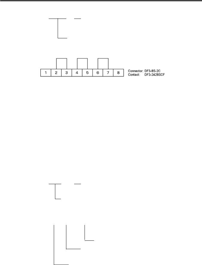
2. SYSTEM MODE
EO13-33002
(Revision Date: Jul. 24, 2008)
2.1 Self-diagnostic Test
(11) Internal Serial Interface Check
EX.232C NG
 OK: The circuit has no problem.
NG (Not good): The circuit has a problem or loopback jig is not attached.
Internal Serial Interface
Connect the jig like below to the serial interface connector and perform a loop back check.
(12)SIO Interface check
Result of optional serial interface check is printed.
SIO NG |
|
NG |
|
|||||||||
|
|
|
|
|
|
|
|
|
|
|
DIN |
OK: The circuit has no problem. |
|
|
|
|
|
|
|
|
|
|
|
||
|
|
|
|
|
|
|
|
|
|
|
|
NG (Not good): The circuit has a problem or loopback jig |
|
|
|
|
|
|
|
|
|
|
|
|
is not attached. |
|
|
|
|
|
|
|
DSUB OK: The circuit has no problem. |
|||||
|
|
|
|
|
|
|
||||||
|
|
|
|
|
|
|
|
|
|
|
NG (Not good): The circuit has a problem or loopback jig is not |
|
|
|
|
|
|
|
|
|
|
|
|
|
attached. |
|
|
|
|
Optional Serial Interface |
||||||||
|
|
|
|
|||||||||
(13)Strip sensor check
Result of a check of the strip sensor on optional strip module is printed.
STRIP NG
 OK: No problem
NG (Not good): There is a problem or a jig is not attached.
Strip sensor
(14) RFID module check |
|
|
|
|
|
|||||
Results of a RFID module check is printed. |
|
|
|
|
|
|||||
|
RFID OK #00RV972 |
|
(EU0) |
|||||||
|
|
|
|
|
|
|
|
|
|
Destination EU0: Europe |
|
|
|
|
|
|
|
|
|
|
|
RFID module version (Printed only when the result is OK.)
OK: The RFID module has no problem.
NG (No good): The RFID module has a problem or loop back jig is not attached.
RFID module
2-16

2. SYSTEM MODE
EO13-33002
2.1 Self-diagnostic Test
2.1.5 Print Head Element Check
This function is used to check for any broken thermal elements of the print head.
If blurred print or missing dots occurs, this check helps you find whether the thermal elements are actually broken or the print head is just stained.
Also, use this check just after a replacement of a print head to find an initial failure.
When the Self-Diagnostic Test result is printed, the message returns to “<1>DIAG. Vx.x”. Press the [PAUSE] key three times and [FEED] key twice.
The printer is ready to check the print head to see if there is any problem with the print head. Press the [PAUSE] key to start.
<1>DIAG. Vx.x |
|
|
|
|
<1>DIAG. Vx.x |
|
[PAUSE] |
|
|
||
HEAD CHECK |
|
|
|
CHECKING |
|
|
|
|
|
If there is no problem with the print head, the print head check is complete. Press the [PAUSE] key to return to “<1>DIAG. Vx.x”.
<1>DIAG. Vx.x NORMAL END
If there is a problem with the print head, the following message is displayed.
<1>DIAG. Vx.x HEAD ERROR
Press the [PAUSE] key to return to “<1>DIAG. Vx.x”.
NOTES: 1. Make sure that the Top Cover is closed before starting the print head check.
2.If “HEAD ERROR” appears, the print head element may be damaged. Replace the print head.
3.The print head element check can be performed at the power on time. For selecting this function, refer to Section 2.2 Parameter Setting.
2-17

2. SYSTEM MODE
EO13-33002
2.2 Parameter Setting
2.2 Parameter Setting
Outline of Parameter Setting
In the Parameter Setting mode, various kinds of parameters, such as communication, key, LCD, etc. can be set. This will allow a use of the printer to comply with your operating conditions.
The Parameter Setting menu contains the following:
<2>PARAMETER SET
[PAUSE]
<2>PARAMETER SET FONT CODE PC-850
[PAUSE]
<2>PARAMETER SET ZERO FONT 0
[PAUSE]
<2>PARAMETER SET
SPEED 9600bps
[PAUSE]
<2>PARAMETER SET DATA LENG. 8bits
[PAUSE]
<2>PARAMETER SET STOP BIT 1bit
[PAUSE]
<2>PARAMETER SET PARITY EVEN
[PAUSE]
<2>PARAMETER SET XON+READY AUTO
[PAUSE]
<2>PARAMETER SET LCD ENGLISH
[PAUSE]
<2>PARAMETER SET FORWARD WAIT OFF
[PAUSE]
<2>PARAMETER SET HEAD UP CUT OFF
[PAUSE]
<2>PARAMETER SET RBN SAVE ON (TAG)
[PAUSE]
<2>PARAMETER SET CODE ESC,LF,NUL
[PAUSE]
<2>PARAMETER SET RIBBON NON TRANS
[PAUSE]
<2>PARAMETER SET PEEL OFF STS OFF
[PAUSE]
Character code selection
Character zero selection
Baud rate selection
Data length selection
Stop bit length selection
Parity selection
Flow control code selection
LCD language selection
Auto forward wait selection
Head up cut selection
Ribbon save function selection
Control code selection
Ribbon type selection
Strip wait status selection
<2>PARAMETER SET FEED KEY FEED
[PAUSE]
<2>PARAMETER SET KANJI CODE TYPE1
[PAUSE]
<2>PARAMETER SET EURO CODE B0
[PAUSE]
<2>PARAMETER SET AUTO HD CHK OFF
[PAUSE]
<2>PARAMETER SET ACK/BUSY TYPE1
[PAUSE]
<2>PARAMETER SET WEB PRINTER OFF
[PAUSE]
<2>PARAMETER SET SENS POSI CENTER
[PAUSE]
<2>PARAMETER SET INPUT PRIME OFF
[PAUSE]
<2>PARAMETER SET EX.I/O TYPE1
[PAUSE]
<2>PARAMETER SET PLUG & PLAY OFF
[PAUSE]
<2>PARAMETER SET LBL/RBN END TYPE1
[PAUSE]
<2>PARAMETER SET PRE PEEL OFF OFF
[PAUSE]
<2>PARAMETER SET BACK SPEED STD
[PAUSE]
<2>PARAMETER SET MAXI CODE TYPE1
[PAUSE]
<2>PARAMETER SET PEEL OFF TRQ R0
[PAUSE]
<2>PARAMETER SET STABILIZER ON
[PAUSE]
Feed key function selection
Kanji code selection
Euro code selection
Auto print head check selection
Centronics ACK/BUSY timing selection
Web printer function selection
Media sensor selection
Input prime selection
Expansion I/O interface type selection
Plug & Play selection
Label end/Ribbon end selection
Pre-strip selection
Reverse feed speed selection
Maxi code specification selection
Strip motor torque selection
Stabilizer function selection
NOTE: Baud rate, Data length, Parity, and Transmission control code should be set to the same values as those of the host computer. Failure to do this causes improper operation.
2-18
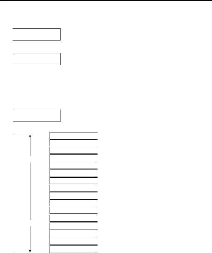
2. SYSTEM MODE
How to Enter Parameter Setting Mode
EO13-33002
2.2 Parameter Setting
Turn on the printer while pressing the [FEED] and the [PAUSE] keys at the same time. Hold both keys until the “<1>DIAG. Vx.x” message appears.
<1>DIAG. Vx.x
Press the [FEED] key. The printer is at the start of the Parameter Setting menu.
<2>PARAMETER SET
2.2.1 Character Code Selection
This parameter is to choose a character code used for printing. Printed characters differ depending on a chosen character code and font. For details of characters, refer to the B-SX6T/SX8T Series External Equipment Interface Specification (Printer Command Manual).
When “<2>PARAMETER SET” appears, press the [PAUSE] key.
<2>PARAMETER SET FONT CODE PC-850
Use the [FEED] or [RESTART] key to select a desired option.
FONT CODE PC-8
FONT CODE PC-857
FONT CODE PC-852 [RESTART] FONT CODE PC-850
FONT CODE Arabic
FONT CODE LATIN9
FONT CODE PC1257
FONT CODE PC1254
FONT CODE PC1253
FONT CODE PC1252
FONT CODE PC1251
FONT CODE PC1250
[FEED]
FONT CODE PC-850
FONT CODE PC-851
FONT CODE PC-866
FONT CODE UTF-8
After selecting a character code, press the [PAUSE] key.
NOTES: 1. When pressing the [FEED] and [RESTART] keys at the same time in the parameter setting, the message returns to “<2>PARAMETER SET”.
2.If holding the [FEED] or [RESTART] key for 0.5 seconds or longer in the parameter setting the key is entered continuously.
3.A changed parameter becomes effective by pressing the [PAUSE].
2-19
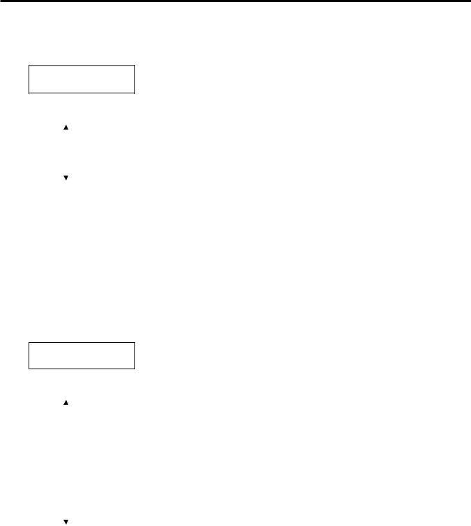
2. SYSTEM MODE
EO13-33002
2.2 Parameter Setting
2.2.2 Character Zero Selection
This parameter is to choose the way to indicate zero between “0” and “Ø”. When “<2>PARAMETER SET” appears, press the [PAUSE] key twice.
<2>PARAMETER SET ZERO FONT 0
Use the [FEED] or [RESTART] key to select a desired option.
|
|
|
|
|
|
|
|
|
|
|
|
|
|
|
|
|
|
|
[RESTART] |
|
ZERO FONT |
0 |
(Without slash) |
|||
|
|
|
|
|
|
|
|
|
|
|
|
|
|
|
|
|
|
|
|
[FEED] |
|
|
|
|
||
ZERO FONT |
Ø |
(With slash) |
||||||
|
|
|
|
|
|
|
|
|
|
|
|
|
|
|
|
|
|
After selecting a character zero, press the [PAUSE] key.
NOTE: The following fonts do not support a zero with slash.
Bit Map Font: OCR-A, OCR-B, GOTHIC 725 Black, Kanji, Chinese
Outline Font: Price Font 1, Price Font 2, Price Font 3, DUTCH 801 Bold, BRUSH 738 Regular, GOTHIC 725 Black, True Type Font
2.2.3 Baud Rate Selection
This parameter is to choose a baud rate of the RS-232C interface. When the printer communicates with a host computer by serial interface, be sure to match the setting with the host.
When “<2>PARAMETER SET” appears, press the [PAUSE] key until the following display appears.
<2>PARAMETER SET
SPEED 9600bps
Use the [FEED] or [RESTART] key to select a desired option.
|
|
|
|
|
|
SPEED 115200 bps |
|
|
|
|
|
|
|||
|
|
|
|
|
|
|
|
|
|
|
|
|
|
|
|
|
[RESTART] |
|
SPEED 38400 bps |
||||
|
|
|
|
|
|
|
|
|
|
|
|
|
|
SPEED 19200 bps |
|
|
|
|
|
|
|
|
|
|
|
|
|
|
|
|
|
|
|
|
|
|
|
SPEED |
9600 bps |
|
|
|
|
|
|
|
|
|
|
|
|
|
|
|
|
|
|
[FEED] |
|
|
SPEED |
4800 bps |
|
|
|
|
|
|
|
|
|
|
|
|
|
|
|
|
|
|
|
|
|
|
|
SPEED |
2400 bps |
|
|
|
|
|
|
|
|
|
|
|
|
|
|
|
|
After selecting a baud rate, press the [PAUSE] key.
2-20
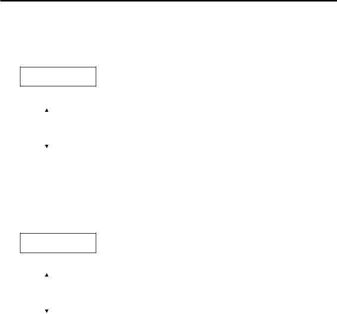
2. SYSTEM MODE
EO13-33002
2.2 Parameter Setting
2.2.4 Data Length Selection
This parameter is to choose a communication data length of the RS-232C interface.
7 bits is used when transmitting alphanumeric data only. 8 bits is used to when transmitting special characters. Be sure to match a setting with a host computer.
When “<2>PARAMETER SET” appears, press the [PAUSE] key until the following display appears.
<2>PARAMETER SET DATA LENG. 8bits
Use the [FEED] or [RESTART] key to select a desired option.
|
|
|
|
|
|
|
|
|
|
|
|
|
|
|
[RESTART] |
|
DATA LENG. 8bits |
|||
|
|
|
|
|
|
|
|
|
[FEED] |
|
DATA LENG. 7bits |
||
|
|
|
|
|
|
|
|
|
|
|
|
|
|
|
|
|
|
|
|
|
After selecting a data length, press the [PAUSE] key.
2.2.5 Stop Bit Length Selection
This parameter is to choose a stop bit length of the RS-232C interface. Be sure to match a setting with a host computer.
When “<2>PARAMETER SET” appears, press the [PAUSE] key until the following display appears.
<2>PARAMETER SET STOP BIT 1bit
Use the [FEED] or [RESTART] key to select a desired option.
|
|
|
|
|
|
|
|
|
|
|
|
|
|
|
|
|
[RESTART] |
|
STOP BIT |
1bit |
|||
|
|
|
|
|
|
|
|
|
|
[FEED] |
|
STOP BIT |
2bits |
||
|
|
|
|
|
|
|
|
|
|
|
|
|
|
|
|
|
|
|
|
|
|
|
|
After selecting a stop bit, press the [PAUSE] key.
2-21
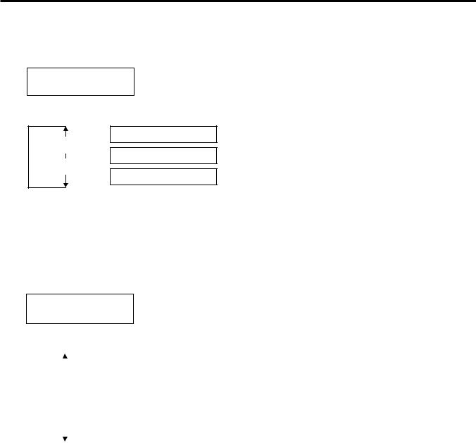
2. SYSTEM MODE
EO13-33002
2.2 Parameter Setting
2.2.6 Parity Selection
This parameter is to choose the parity of the RS-232C interface.
When “<2>PARAMETER SET” appears, press the [PAUSE] key until the following display appears.
<2>PARAMETER SET PARITY NONE
Use the [FEED] or [RESTART] key to select a desired option.
PARITY EVEN
[RESTART]
PARITY ODD
[FEED]
PARITY NONE
After selecting the parity, press the [PAUSE] key.
2.2.7 Flow Control Code Selection
This parameter is to choose a flow control code of the RS-232C interface.
When “<2>PARAMETER SET” appears, press the [PAUSE] key until the following display appears.
<2>PARAMETER SET XON+READY AUTO
Use the [FEED] or [RESTART] key to select a desired option.
|
|
|
|
|
|
XON/XOFF AUTO |
XON/XOFF mode |
|
|
|
|
|
|||
|
|
|
|
|
|||
|
|
|
|
|
|
|
XON/XOFF+READY/BUSY (DTR) mode |
|
|
|
|
|
|
|
|
|
|
|
|
|
|
XON+READY AUTO |
|
|
[RESTART] |
||||||
|
|
|
|
||||
|
|
|
|
|
|
|
READY/BUSY (DTR) mode |
|
|
|
|
|
|
READY/BUSY |
|
|
|
|
|
|
|
|
|
|
|
[FEED] |
|
|
|
XON/XOFF mode |
|
|
|
|
|
XON/XOFF |
|||
|
|
|
|
|
|
||
|
|
|
|
|
|
|
RTS mode |
|
|
|
|
|
|
|
|
|
|
|
|
|
|
READY/BUSY RTS |
|
|
|
|
|
|
|||
|
|
|
|
|
|||
|
|
|
|
|
|
|
|
After selecting a flow control code, press the [PAUSE] key.
NOTE: The following is the detailed descriptions for each transmission control code.
1)XON/XOFF AUTO
At the power on time, the printer outputs XON. At the power off time, the printer outputs XOFF.
2)XON+READY AUTO
At the power on time, the printer outputs XON. At the power off time, the printer outputs XOFF.
3)READY/BUSY
At the power on time, the DTR signal output from the printer turns to High level (READY). At the power off time, the printer does not output XOFF.
4)ON/XOFF
At the power on time, the printer outputs XON. At the power off time, the printer does not output XOFF.
5)READY/BUSY RTS
At the power on time, the RTS signal output from the printer turns to High level (READY). At the power off time, the printer does not output XOFF.
2-22
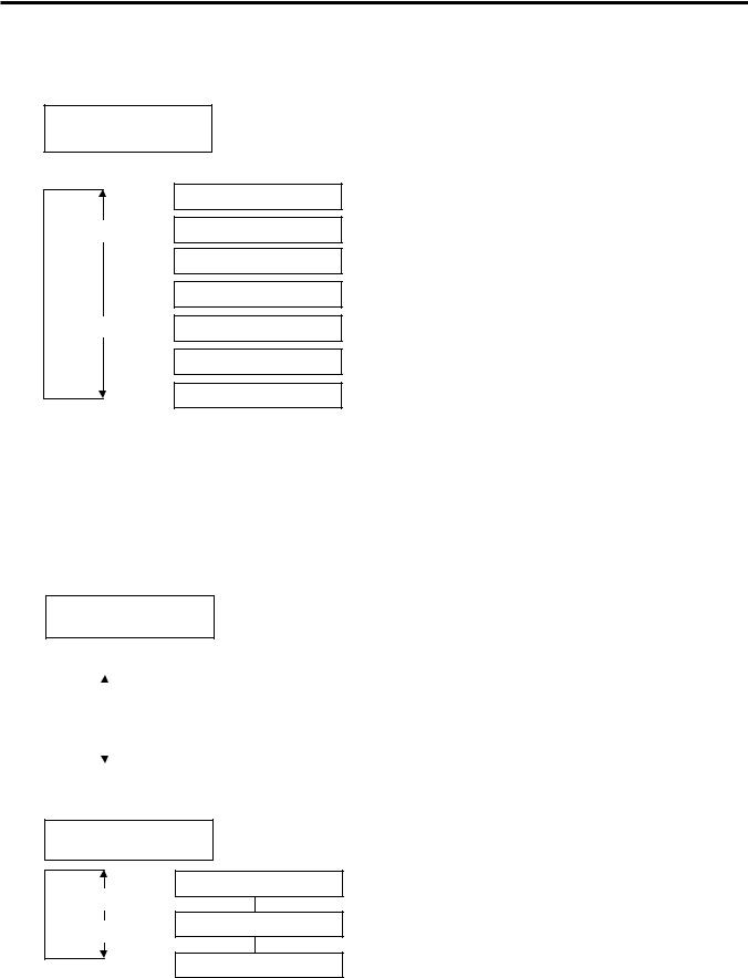
2. SYSTEM MODE
EO13-33002
2.2 Parameter Setting
2.2.8 LCD Language Selection
This parameter is to choose a language in which the LCD message is displayed.
When “<2>PARAMETER SET” appears, press the [PAUSE] key until the following display appears.
<2>PARAMETER SET LCD ENGLISH
Use the [FEED] or [RESTART] key to select a desired option.
ENGLISH
[RESTART] ITALIAN
JAPANESE
SPANISH
[FEED] DUTCH
FRENCH
GERMAN
After selecting a language, press the [PAUSE] key.
2.2.9 Auto Forward Wait Selection
This parameter is to choose whether to activate the Auto Forward Wait function or not.
This function, used in the cut mode, automatically feeds the media forward for about 14 mm if there is more than 1-second idle time after printing, to prevent the top edge of the media from curling.
When “<2>PARAMETER SET” appears, press the [PAUSE] key until the following display appears.
<2>PARAMETER SET FORWARD WAIT OFF
Use the [FEED] or [RESTART] key to select a desired option.
|
|
|
|
|
|
|
Activated |
|
|
|
|
|
|
FORWARD WAIT ON |
|
|
[RESTART] |
|
|||||
|
|
|
|
|
|
|
|
|
|
[FEED] |
|
|
FORWARD WAIT OFF |
Not activated |
|
|
|
|
|
|
|
|
|
|
|
|
|
|
|
|
|
When ON is selected, pressing the [PAUSE] key will result that the LCD Message Display shows the stop position fine adjustment value setting screen.
<2>PARAMETER SET
POSITION +0.0mm
[RESTART] |
POSITION +5.0mm |
|
|
[FEED] |
POSITION +0.0mm |
|
|
|
POSITION -5.0mm |
[FEED] key: |
Pressing the [FEED] key one time causes a –0.1 mm change, up to –5.0 mm. |
[RESTART] key: Pressing the [RESTART] key one time causes a +0.1 mm change, up to +5.0 mm.
After selecting an auto forward wait, press the [PAUSE] key.
2-23
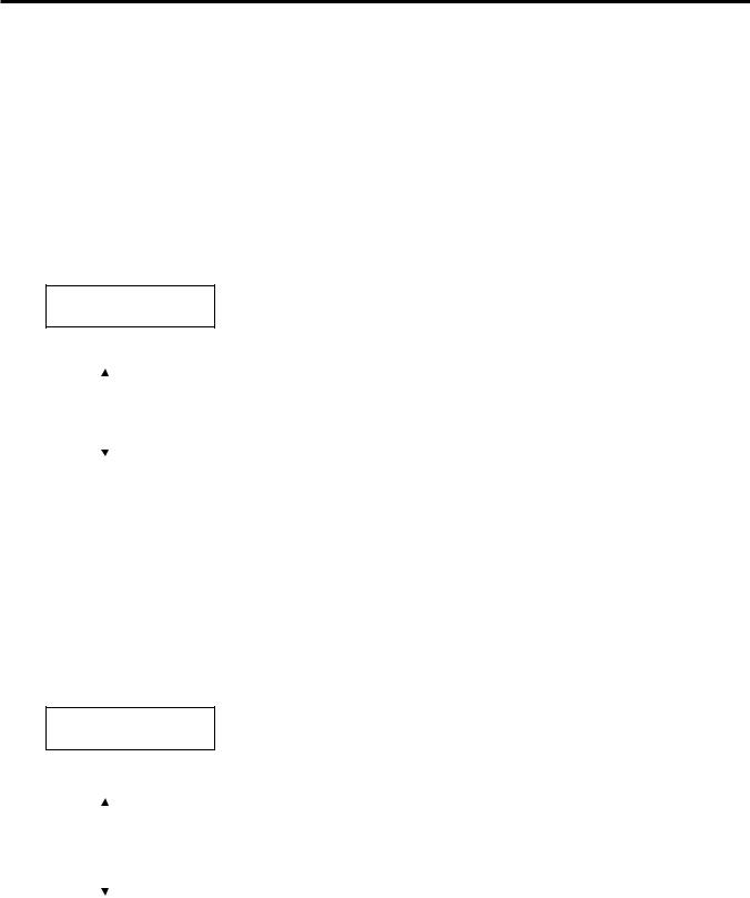
2. SYSTEM MODE
EO13-33002
2.2 Parameter Setting
NOTES: 1. If the printer is not used for a few days, the top edge of the media may become curly, which may cause a paper jam. The Auto Forward Wait Function prevents this problem since the media feed amount is increased so that the media stops past the platen.
2.When the Stop Position Fine Adjustment Value is set in + direction, the media will stop past the media outlet.
When the value is set in – direction, the media will stop inside the media outlet.
3.This setting will be useful to fine adjust the cut position of labels.
2.2.10Head Up Cut Selection
This parameter is to choose whether to activate the head up action in the cut issue.
This function prevents ribbon smudges by raising the print head during a reverse feed to the print start position.
When “<2>PARAMETER SET” appears, press the [PAUSE] key until the following display appears.
<2>PARAMETER SET HEAD UP CUT OFF
Use the [FEED] or [RESTART] key to select a desired option.
|
|
|
|
|
|
|
|
Activated |
|
|
|
|
|
|
HEAD UP CUT |
ON |
|
|
[RESTART] |
|
||||||
|
|
|
|
|
|
|
|
|
|
|
[FEED] |
|
|
HEAD UP CUT |
OFF |
Not activated |
|
|
|
|
|
|
|
|
|
|
|
|
|
|
|
|
|
|
|
After selecting the head up action in cut issue, press the [PAUSE] key.
NOTES: 1. For the B-SX6T, this function is available only when an optional ribbon saving module (B-SX908-R- QM-R) is installed
2. The print head may not be raised depending on the rise of the solenoid’s temperature.
2.2.11Ribbon Save Function Selection
This parameter is to choose whether to activate the Ribbon Saving function or not.
This function enables reducing the ribbon loss caused by taking up unused ribbon during non-print areas. When “<2>PARAMETER SET” appears, press the [PAUSE] key until the following display appears.
<2>PARAMETER SET RBN SAVE ON (TAG)
Use the [FEED] or [RESTART] key to select a desired option.
|
|
|
|
|
|
RBN SAVE ON (TAG) |
Activated (When the head lever is set to position 2.) |
|
|
|
|
|
|
|
|||
|
[RESTART] |
|
|
|
||||
|
|
|||||||
|
|
|
|
|
|
RBN SAVE ON (LBL) |
Activated (When the head lever is set to position 1.) |
|
|
|
[FEED] |
|
|
Not activated |
|||
|
||||||||
RBN SAVE OFF |
||||||||
|
|
|
|
|
|
|||
|
|
|
|
|
|
|
|
|
After selecting the ribbon save function, press the [PAUSE] key.
NOTES: 1. For the B-SX6T, this function is available only when an optional ribbon saving module (B-SX908-R- QM-R) is installed.
2.If this parameter is set to ON without installing a ribbon saving module, the ribbon will be slack during paper feed or printing, and as a result, printing cannot be performed properly.
Also, be sure to conform the choice to the actual head lever position. Failure to do this may disable proper ribbon saving function.
2-24
Loading...