


 Loading...
TOSHIBA Thermal Printer
B-EV4 SERIES
 Printer Manual
Document No. EO18-33025
Original Nov, 2008 (Revised )
This manual includes the contents of the Product Description, and Maintenance Manual.
PRINTED IN JAPAN

|
|
|
|
EO18-33025 |
|
|
|
|
(Revision Date: Mar. 27, 2009) |
|
|
|
TABLE OF CONTENTS |
|
|
|
|
|
Page |
1. |
OUTLINE------------------------------------------------------------------------------------------------------------- |
|
1- 1 |
|
|
1.1 |
Features of the B-EV4D/EV4T-------------------------------------------------------------------------- |
1- 1 |
|
|
|
1.1.1 |
Front View ------------------------------------------------------------------------------------------ |
1- 1 |
|
|
1.1.2 |
Rear View ------------------------------------------------------------------------------------------ |
1- 1 |
|
|
1.1.3 |
Interior View---------------------------------------------------------------------------------------- |
1- 2 |
|
1.2 |
Indications of the Model Name ------------------------------------------------------------------------- |
1- 4 |
|
|
1.3 |
Basic Specifications --------------------------------------------------------------------------------------- |
1- 5 |
|
|
1.4 |
Key and LED ------------------------------------------------------------------------------------------------ |
1- 8 |
|
|
1.5 |
Supply Specifications ------------------------------------------------------------------------------------- |
1- 9 |
|
|
|
1.5.1 |
Media Type----------------------------------------------------------------------------------------- |
1- 9 |
|
|
1.5.2 Detection Area of the Transmissive Sensor ---------------------------------------------- |
1-10 |
|
|
|
1.5.3 Detection Area of the Reflective Sensor--------------------------------------------------- |
1-10 |
|
|
|
1.5.4 |
Ribbon---------------------------------------------------------------------------------------------- |
1-11 |
2. |
ELECTRONIC SPECIFICATIONS ---------------------------------------------------------------------------- |
2- 1 |
||
|
2.1 |
Block Diagram ---------------------------------------------------------------------------------------------- |
2- 1 |
|
|
2.2 |
Main PC Board Layout------------------------------------------------------------------------------------ |
2- 2 |
|
|
2.3 |
Description of the MAIN PC Board -------------------------------------------------------------------- |
2- 3 |
|
3. |
REPLACING THE IMPORTANT PARTS ------------------------------------------------------------------- |
3- 1 |
||
|
3.1 |
Replacing the Top Cover--------------------------------------------------------------------------------- |
3- 2 |
|
|
|
3.1.1 |
B-EV4T model------------------------------------------------------------------------------------- |
3- 2 |
|
|
3.1.2 |
B-EV4D model ------------------------------------------------------------------------------------ |
3 -3 |
|
3.2 |
Replacing the Lower Cover------------------------------------------------------------------------------ |
3- 6 |
|
|
3.3 |
Replacing the Main PC Board -------------------------------------------------------------------------- |
3- 7 |
|
|
3.4 |
Replacing the Platen Ass’y ------------------------------------------------------------------------------ |
3- 9 |
|
|
3.5 |
Replacing the Print Head Ass’y------------------------------------------------------------------------ |
3-10 |
|
|
|
3.5.1 |
B-EV4T model------------------------------------------------------------------------------------ |
3-10 |
|
|
3.5.2 |
B-EV4D model ----------------------------------------------------------------------------------- |
3-12 |
|
3.6 |
Replacing the Stepping Motor ------------------------------------------------------------------------- |
3-15 |
|
|
3.7 |
Replacing the Gear Cover ------------------------------------------------------------------------------ |
3-17 |
|
|
3.8 |
Replacing the Feed Button PC Board---------------------------------------------------------------- |
3-19 |
|
|
3.9 |
Replacing the Cover Open Sensor ------------------------------------------------------------------- |
3-20 |
|
|
3.10 |
Replacing the Ribbon Sensor -------------------------------------------------------------------------- |
3-21 |
|
|
3.11 |
Replacing the Black Mark Sensor--------------------------------------------------------------------- |
3-22 |
|
|
3.12 |
Replacing the Feed Gap Sensor (Lower) ----------------------------------------------------------- |
3-24 |
|
|
3.13 |
Replacing the Feed Gap Sensor (Upper) ----------------------------------------------------------- |
3-26 |
|
4. |
TROUBLESHOOTING ------------------------------------------------------------------------------------------- |
4- 1 |
||
|
4.1 |
LED Status--------------------------------------------------------------------------------------------------- |
4- 1 |
|
|
4.2 |
Print Quality-------------------------------------------------------------------------------------------------- |
4- 2 |
|
5. |
MAINTENANCE---------------------------------------------------------------------------------------------------- |
5- 1 |
||
6. |
FIRMWARE DOWNLOAD MODE----------------------------------------------------------------------------- |
6- 1 |
||
CAUTION!
1.This manual may not be copied in whole or in part without prior written permission of TOSHIBA TEC.
2.The contents of this manual may be changed without notification.
Copyright © 2008
by TOSHIBA TEC CORPORATION All Rights Reserved
570 Ohito, Izunokuni-shi, Shizuoka-ken, JAPAN
1. OUTLINE
EO18-33025
1.1 Feature of the B-EV4D/EV4T
1. OUTLINE
1.1 Feature of the B-EV4D/EV4T
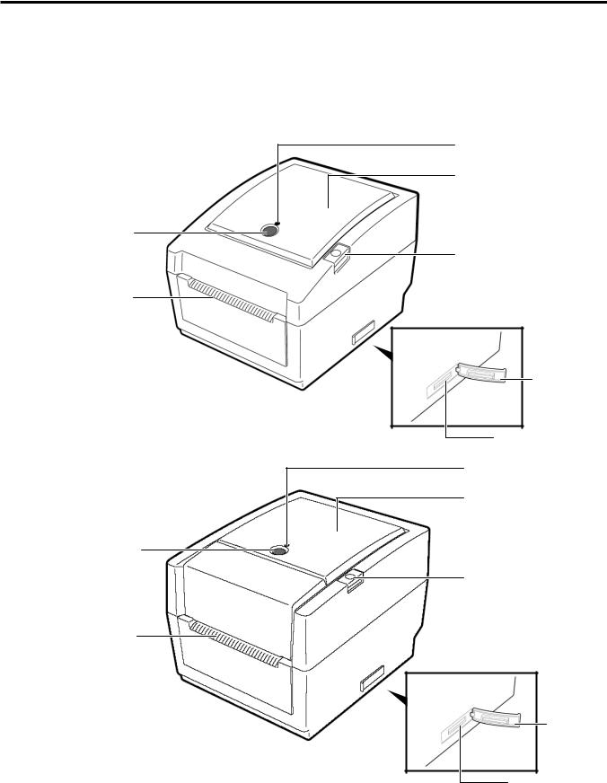
1.1.1 Front View
(1) B-EV4D
STATUS Lamp
Media View Window
FEED Button
Top Cover Release Button
Media Outlet
SD Card
Slot Cover
SD Card Slot
(2) B-EV4T
STATUS Lamp
Media View Window
FEED Button
Top Cover Release Button
Media Outlet
SD Card
Slot Cover
SD Card Slot
1-1

1. OUTLINE
EO18-33025
1.1 Feature of the B-EV4D/EV4T
1.1.2 Rear View
Fanfold paper slot
Ethernet interface
USB Interface
Connector
Parallel Interface
Connector (Centronics)
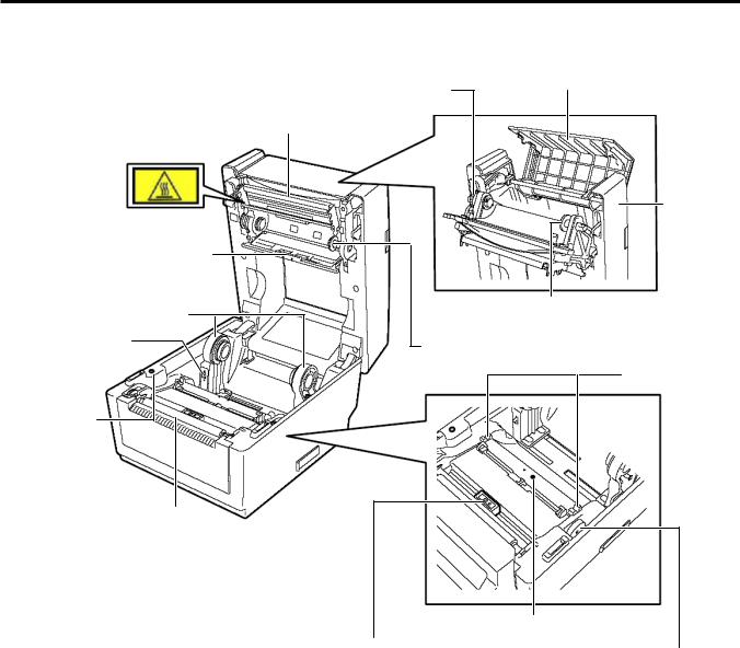
1.1.3 Interior
(1) B-EV4D
Print Head
Media Holder
Media Holder Lock Switch
Cover Open Sensor 
Media Guide
Power Switch
Power Jack
Serial Interface Connector (RS-232C)
Top Cover
Feed Gap Sensor (Receiver)
Media Guide
Adjustment Dial
Black Mark Sensor
Feed Gap Sensor (Transmitter)
Platen
1-2
1. OUTLINE
EO18-33025
1.1 Feature of the B-EV4D/EV4T
(2) B-EV4T
Feed Gap Sensor
(Receiver)
Media Holder
Media Holder
Lock Switch
Cover Open
Sensor
Ribbon Access Cover
Ribbon Rewind Gear
Print Head
Top Cover
Spring Guide Wheel (Take-up side)
Spring Guide Wheel (Supply side)
Media Guide
Platen
Feed Gap Sensor (Transmitter)
Black Mark Sensor
Media Guide
Adjustment Dial
1-3

1. OUTLINE
EO18-33025
1.2 Indication of the Model Name
1.2 Indication of the Model Name
B - E V 4 D - G S 14 - QM - R
 RoHS compliance model
Destination country/Region code QM: Standard for World Wide
Interface
14: USB, Serial, Parallel and Ethernet
Issue mode S: Standard
Dot density of the print haed. G: 8dots/mm (203dpi)
T: 12dots/mm (300dpi)
Print mode
D: Direct thermal print T: Thermal transfer print
Print width 4: 4inch
1-4

1. OUTLINE
EO18-33025
1.3 Basic Specifications
1.3 Basic Specifications
Model |
|
B-EV4D |
B-EV4T |
|
General |
Construction |
Double walled casing & Clam shell design |
||
Maintenance |
No tool required to repair thermal head and platen |
|||
Characteristics |
||||
Paper holder |
No roll spindle & No paper holder spring |
|||
Printer |
Print method |
Direct thermal printing |
Direct thermal/thermal transfer |
|
characteristics |
|
printing |
||
|
|
|||
Resolution |
GS model: 203 dpi (8 dots/mm) |
|
||
|
|
|||
|
TS model 300 dpi (12 dots/mm) |
|
||
|
|
|
||
|
Print width |
GS model: 203 dpi Max. 4.25” (108 mm) |
||
|
TS model: 300 dpi Max. 4.17”(106mm) |
|||
|
|
|||
|
|
GS model: 203 dpi, Max. 39” (999 mm) |
||
|
Print length |
|||
|
TS model: 300 dpi, Max. 39” (999 mm) |
|||
|
|
|||
|
Print Speed |
GS model: 203 dpi, 2, 3, 4, 5”/sec, 2, 3 ips for peel-off |
||
|
TS model: 300 dpi, 2, 3, 4”/sec, 2 ips for peel-off |
|||
|
|
|||
|
RAM |
8 MB SDRAM |
|
|
|
Flash ROM |
4 MB |
|
|
|
User area |
832 KB |
|
|
|
Optional memory |
SD Card |
|
|
|
Media sensors |
Feed gap sensor |
|
|
|
|
Black mark sensor |
|
|
|
|
Cover open (Reflective) |
|
|
|
|
Ribbon end (Reflective encoder sensor) |
||
|
I/F (User installable) |
RS-232C (Max. 115.2Kbps) |
|
|
|
|
Centronics (SPP) |
|
|
|
|
USB 2.0 (Support Full Speed) |
|
|
|
|
LAN 10/100Base |
|
|
|
Barcode Linear |
UPC-A, UPC-E, EAN8/13, |
|
|
|
(Same as B-SA4 |
UPC-A add on 2&5, |
|
|
|
series) |
EAN-8/13 add on 2&5, |
|
|
|
|
Code39, Code93, |
|
|
|
|
Code128, EAN128, |
|
|
|
|
NW7, MSI, |
|
|
|
|
Industrial 2 of 5, |
|
|
|
|
ITF, Postnet, |
|
|
|
|
RM4SCC, KIX-code, |
|
|
|
|
Plessey, RSS14 |
|
|
|
Printer Language |
TPCL (Refer to External Equipment I/F manual) |
||
|
2D Barcode |
Data Matrix, PDF417 |
|
|
|
(Same as B-SV4 |
Maxicode, QR code |
|
|
|
series) |
Micro PDF417 |
|
|
1-5

1. OUTLINE
EO18-33025
(Revision Date: Mar. 27, 2009)
1.3 Basic Specifications
Model |
|
B-EV4D |
|
B-EV4T |
||
Printer |
Fonts |
Bitmap: Alpha-numeric 20 types |
+ Kanji 4 types |
|||
characteristics |
Outline: 2 types |
|
|
|
||
|
|
Writable characters, Optional TTF |
||||
|
LED |
One LED w/ 3 colors (w/ silk screen print of “STATUS”) |
||||
|
Key |
Feed key (w/ silk screen print of “ FEED”) |
||||
|
Switch |
Power S/W |
|
|
|
|
|
|
1” (25.4 mm) to 4.41” (112 mm) |
|
|
||
Media |
Label width |
|
|
|||
characteristics |
Label length |
203 dpi: 0.6” (15 mm) to 39” (999 mm) |
||||
|
300 dpi: 0.6” (15mm) to 39” (999 mm) |
|||||
|
|
|||||
|
Label length (Strip |
25.4~152.4 mm (1”~6”) |
|
|
||
|
mode) |
|
|
|||
|
|
|
|
|
||
|
Label length (Cutter |
25.4~999 mm (1”~39”) |
|
|
||
|
mode) |
|
|
|||
|
Max. 5” (127 mm) |
|
|
|||
|
Roll diameter |
|
|
|||
|
Core diameter |
1” (25.4 mm) to 1.5” (38 mm) |
|
|
||
|
Media thickness |
0.0024” (0.06 mm) to 0.0075” (0.19 mm) |
||||
|
Media types |
Roll-fed, Fanfold, Die-cut, |
|
|
||
|
Continuous, Tag stock, Receipt |
|
|
|||
|
|
|
Max. 40 mm |
|||
Ribbon |
Outside diameter |
---------- |
|
|||
characteristics |
Standard length |
---------- |
|
110 m |
||
|
Ribbon width |
---------- |
|
1.33” (33.8 mm) to 4.30” (110 |
||
|
|
mm) |
||||
|
|
|
|
|
||
|
ID core |
---------- |
|
0.5” (12.7 mm) |
||
Operating |
Operating |
41 degF (5 degC) to 104 degF (40 degC) |
||||
|
temperature |
|||||
characteristics |
|
|
|
|
||
Storage temperature |
-40 degF (-40 degC) to 140 degF (60 degC) |
|||||
|
||||||
|
Operating humidity |
25 to 85 % (Non-condensing R.H) |
||||
|
Storage humidity |
10 to 90 % (Non-condensing R.H) |
||||
|
|
AC Adapter: 100-240 VAC, 50/60 Hz ± 10% |
||||
|
|
Power consumption |
|
|
||
|
|
G Type (203dpi) |
During standby: 100mA (2.4W) |
|||
|
Electrical |
|
During a print job: 3A (72W) |
|||
|
T Type (300dpi) During standby: 100mA (2.4W) |
|||||
|
|
|||||
|
|
Rush Current |
During a print job: 2.5A (60W) |
|||
|
|
≤45A |
|
|
||
|
|
110V input: |
|
|
||
|
|
220V inpt: |
≤90A |
|
|
|
|
Agency approvals |
FCC Class B |
|
|
|
|
|
|
C-Tick |
|
|
|
|
|
|
CE |
|
|
|
|
|
|
TUV |
|
|
|
|
|
|
UL, cUL |
|
|
|
|
|
|
CCC |
|
|
|
|
|
|
VCCI Class B (Japanese model), PSE (AC adapter, Japanese |
||||
|
|
model) |
|
|
|
|
|
Environmental |
RoHS |
|
|
|
|
|
complaint |
WEEE |
|
|
|
|
1-6

1. OUTLINE
EO18-33025
1.3 Basic Specifications
Model |
|
B-EV4D |
B-EV4T |
|
Physical |
Width |
7.8” (198 mm) |
7.8” (198 mm) |
|
characteristics |
Height |
6.7” (169.5 mm) |
6.8” (173 mm) |
|
Depth |
10.2” (258 mm) |
10.2” (258 mm) |
||
|
||||
|
Weight |
2.5Kg or less |
2.5Kg or less |
|
Related products |
Options |
Full cutter module (B-EV204-F-QM-R) |
||
|
|
Partial cutter module (B-EV204-P-QM-R) |
||
|
|
Strip module (B-EV904-H-QM-R) |
|
|
|
|
External Media Holder (B-EV904-PH-QM-R) |
||
|
|
AC Adapter Cover Kit (B-EV904-AC-QM-R) |
||
|
Accessories |
Start–up CDROM |
|
|
|
|
Power Adapter |
|
|
|
|
Supply Loading Instruction |
|
|
|
|
Safety Precautions |
|
|
1-7
1. OUTLINE
1.4 Key and LED
EO18-33025
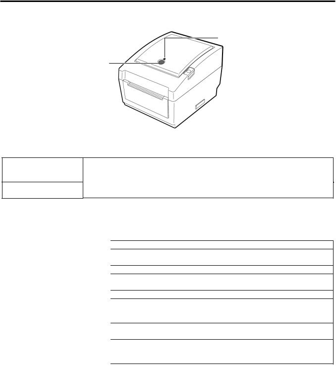
1.4 Key and LED
STATUS Lamp
FEED Button
The [FEED] button operates as FEED button or PAUSE button depending on the printer statuses.
As the FEED button
As the PAUSE button
Pressing this button when the printer is in online state causes a media feed. Pressing this button after removing a cause of an error returns the printer to online state.
Pressing this button during printing stops printing after completing the current label. The printer resumes printing when this button is pressed again.
The indicator lamp lights up or flashes in different colors depending on the printer statuses. The main indicator lamp statuses and the corresponding printer statuses are shown inside the top cover.
Color |
Status |
Printer status |
|
Green |
Lights up |
Stand-by |
|
Green |
Flashes fast |
Communicating with a host. |
|
Green |
Flashes slowly |
Printing is temporarily stopped (paused). |
|
Green/Red |
Flashes slowly |
The print head temperature exceeded the upper limit. |
|
Red |
Lights up |
A communication error occurred. (Only when the RS-232C is used.) |
|
Red |
Flashes fast |
A paper jam occurred. |
|
Red |
Flashes at |
The media is ended. |
|
medium speed |
|
||
|
An issue or feed was attempted with the top cover opened. |
||
Red |
Flashes slowly |
||
Orange |
Flashes fast |
A paper jam occurred din the cutter unit. (Only when the cutter unit is |
|
fitted.) |
|||
|
|
||
Orange |
Flashes at |
The ribbon is ended. |
|
medium speed |
|
||
|
The top cover is open. |
||
None |
Unlit |
1-8
1. OUTLINE
EO18-33025
1.5 Supply Specifications
1.5 Supply Specifications
1.5.1 Media Type
The table below shows the size and shape of the media that can be used on this printer.
Label |
Black Mark |
Tag paper |
Black Mark |
(on reverse side) |
(on reverse side) |
|
g |
g |
|
Cut position |
|
|
e |
e |
|
f |
|
|
|
|
d |
Feed Direction |
h |
c |
|
d |
|
|
c |
|
|
|
|
|
|
|
Unit: mm (inch) |
|
|
|
|
|
|
|
|
|
|
|
Issue mode |
Batch mode |
|
Strip mode |
|
Cut mode |
||
Item |
|
|
||||||
|
|
|
|
|
||||
c Width including backing paper |
|
|
25.4 to 112 (1.0 to 4.41) |
|
|
|||
d Media width |
|
22.4 to 109 (0.88 to 4.29) |
|
|||||
|
|
203 dpi |
10 to 999 |
|
25.4 to 152.4 |
|
25.4 to 999 |
|
|
Label |
(0.39 to 39.3) |
|
(1.0 to 6) |
|
(1.0 to 39.3) |
||
|
|
|
|
|||||
|
300 dpi |
10 to 457.2 |
|
25.4 to 152.4 |
|
25.4 to 457.2 |
||
|
|
|
|
|||||
e Media pitch |
|
(0.39 to 18.0) |
|
(1.0 to 6) |
|
(1.0 to 18.0) |
||
|
|
|
|
|||||
|
203 dpi |
10 to 999 |
|
----- |
|
25.4 to 999 |
||
|
|
|
|
|||||
|
Tag |
(0.39 to 39.3) |
|
|
(1.0 to 39.3) |
|||
|
|
|
|
|
||||
|
300 dpi |
10 to 457.2 |
|
----- |
|
25.4 to 457.2 |
||
|
|
|
|
|||||
|
|
(0.39 to 18.0) |
|
|
(1.0 to 18.0) |
|||
|
|
|
|
|
|
|||
|
|
203 dpi |
8 to 997 |
|
23.4 to 150.4 |
|
19.4 to 993 |
|
f Media length |
(0.31 to 39.25) |
|
(0.92 to 5.92) |
|
(1.0 to 39.1) |
|||
|
|
|
||||||
300 dpi |
8 to 455.2 |
|
23.4 to 150.4 |
|
19.4 to 451.2 |
|||
|
|
|
|
|||||
|
|
(0.31 to 17.9) |
|
(0.92 to 5.92) |
|
(1.0 to 17.76) |
||
|
|
|
|
|
||||
g Gap/black mark length |
2.0 to 10.0 (0.08 to 0.39) |
|
6.0 to 10.0 |
|||||
|
(0.24 to 0.39) |
|||||||
|
|
|
|
|
|
|
||
h Black mark width |
|
|
Min. 8.0 (0.31) |
|
|
|||
Thickness |
|
0.06 to 0.19 (0.0024 to 0.0075) |
|
|||||
Max. outer roll diameter |
|
Ø127 (5) |
|
|
||||
Ø214 (8.42): When the optional External Media Roll Hanger is used. |
||||||||
|
|
|
||||||
Roll direction |
Outside (standard), Inside (Refer to NOTE 3) |
|||||||
Inner core diameter |
25.4 to 38.1, or 76.2 (1 to 1.5, or 3) (See NOTE 2.) |
|||||||
1-9
1. OUTLINE
NOTES:
EO18-33025
1.5 Supply Specifications
1.To ensure print quality and print head life use only TOSHIBA TEC approved media.
2.When using a media roll of 76.2-mm (3”) inner core diameter, the 3”-Diameter Media Shaft included in the optional External Media Roll Hanger is required.
3.Precaution for use of labels
When labels are used for printing, please only use outside wound labels. Use of an inside wound label causes a paper jam.
|
Outside wound |
Inside wound |
|
|
|
Label |
Usable |
Not usable |
|
|
|
Tag Paper |
Usable |
Usable |
|
|
|
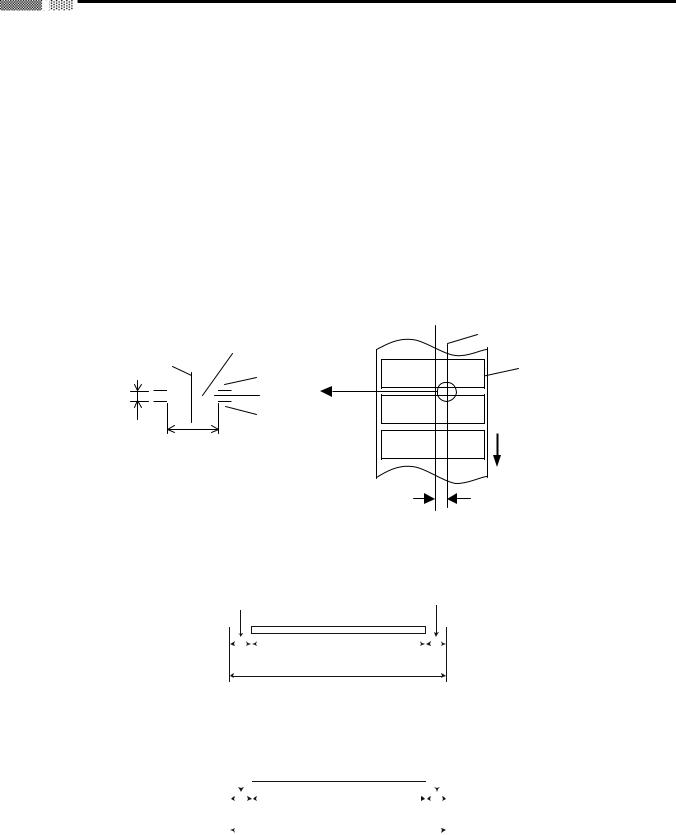
1.5.2 Detection Area of the Transmissive Sensor
The Transmissive sensor is fixed and positioned at 6.35 mm right of the center of the media path. The Transmissive Sensor detects a gap between labels, as illustrated below.
|
Area to be detected. |
Sensor position |
|
|
|
Sensor position |
Print side |
|
|
Label |
|
|
|
|
Min. 2 mm |
Gap |
|
(Min. 6 mm: |
Label |
|
cut mode) |
|
|
|
|
|
|
Min. 8 mm |
Media feed direction |
|
|
|
6.35mm
1.5.3 Detection Area of the Reflective Sensor
The figure below illustrates the relation between the head effective print width and media width. (for GS14 Type)
Out of print range |
|
|
|
|
Print head element |
|
|
|
|
|
Out of print range |
|
|
|
|
|
|
|
|
|
|||
|
|
|
|
|
|
||||||
|
|
|
|
|
|
|
|
|
|
|
|
|
|
|
|
|
|
|
|
|
|
|
|
|
|
|
|
|
|
|
|
|
|
|
|
|
|
|
|
|
|
|
|
|
|
|
|
|
|
|
|
|
|
|
|
|
|
|
|
|
2 mm |
108.0 mm±0.2mm |
|
2 mm |
|||||||
|
|
|
|
|
(Head Effective Print Range) |
|
|
|
|
|
|
112.0 mm (Max. media width)
(for TS14 Type)
|
|
|
|
|
|
|
|
|
|
|
|
|
Out of print range |
Out of print range |
|
|
|
|
|
Print head element |
|
|
|
|
|
|
|
|
|
|
|
|
|
|
|
|
|
|
|||
|
|
|
|
|
|
|
|
|
|
|
|
||
|
|
|
|
|
|
|
|
|
|
|
|
|
|
|
|
|
|
|
|
|
|
|
|
|
|
|
|
|
|
|
|
|
|
|
|
|
|
|
|
|
|
|
|
|
|
|
|
|
|
|
|
|
|
|
|
|
|
|
|
|
|
|
|
|
|
|
|
|
|
|
|
3 mm |
106.0 mm±0.2mm |
|
3 mm |
|
|
||||||
|
|
|
|
|
|
(Head Effective Print Range) |
|
|
|
|
|
|
|
|
|
|
|
|
|
|
|
|
|
|
|
|
|
|
|
|
|
|
|
|
|
|
|
|
|
|
|
112.0 mm (Max. media width)
1-10
1. OUTLINE
EO18-33025
1.5 Supply Specifications
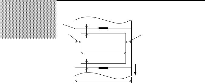
The figure below shows the effective print area on the media.
Start line
1.5mm from the left edge of media
1mm |
Guaranteed print area |
1mm |
1.5mm from the right edge of media
Media feed direction
Media width
(Backing paper width is not included.)
NOTES:
1.Be sure not to print on the 1.5-mm wide area from the media edges (shaded area in the above figure).
2.The centre of media should be positioned at the centre of the print head.
3.Print quality is not guaranteed within 3 mm from the print head stop position (including 1-mm slow-up.)
4.Average print (black) rate should be 15% or less. For bar code print area, the print rate should be 30% or less.
5.Line weight should be 3 to 12 dots.
1.5.4 Ribbon
Type |
Spool type |
|
|
Width |
33.8 mm to 110 mm |
|
|
Length |
Depends on its thickness and outside diameter of core. |
|
|
Max. outside diameter |
40 mm |
|
|
Inside diameter of core |
12.7 mm |
|
|
Roll direction |
Outside |
|
|
NOTES:
1.To ensure print quality and print head life use only TOSHIBA TEC specified ribbons.
2.Too much difference in width between media and ribbon may cause ribbon wrinkles. To avoid ribbon wrinkles use a ribbon for proper media width shown in the above table. Do not use a ribbon that is narrower than media.
3.When discarding ribbons, please follow the local rule.
1-11
2. ELECTRONICS SPECIFICATIONS
EO18-33025
2.1 Block Diagram
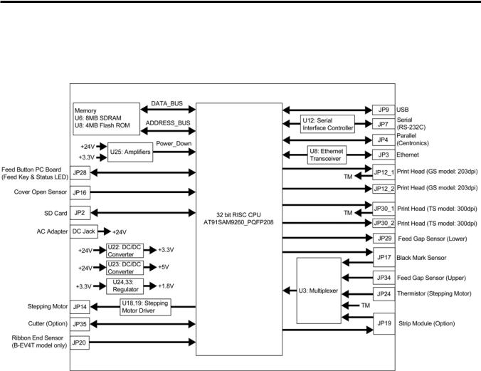
2. ELECTRONIC SPECIFICATIONS
2.1 Block Diagram
2-1
2. ELECTRONICS SPECIFICATIONS
EO18-33025
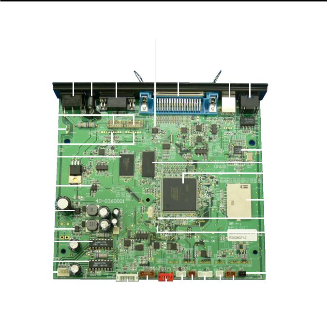
2.2 Main PC Board Layout
2.2 Main PC Board Layout
JP7: Serial (RS-232C) |
|
|
|
U12: Serial Interface Controller |
|||||||||
|
|
|
|||||||||||
|
|
|
|
JP4: Parallel (Centronics) |
|||||||||
DC Jack |
|
|
|
|
|
|
|||||||
|
|
|
|
|
|
|
|
JP9: USB |
|||||
SW1: Power Switch |
|
|
|
|
|
|
|
|
|
|
|||
|
|
|
|
|
|
|
|
|
|
|
|
|
|
|
|
|
|
|
|
|
|
|
|
|
|
|
JP3: Ethernet |
|
|
|
|
|
|
|
|
|
|
|
|
|
(10BASET/100BASETX) |
|
|
|
|
|
|
|
|
|
|
|
|
|
|
|
|
|
|
|
|
|
|
|
|
|
|
|
|
|
|
|
|
|
|
JP12: Print Head |
|
|
|
|
|
|
|
|
|
|
|
|
|
|
|
|
|
|
|
|
|
|
|
|
|
|
|||||||||
|
|
|
|
|
GS model: 203dpi |
|
|
|
|
|
|
|
|
|
|
|
|
|
|
|
|
|
|
|
|
|
|
|
|
|
|
||||||||||
|
|
|
|
|
|
|
|
|
|
|
|
|
|
|
|
|
|
|
|
|
|
|
|
|
|
|
|
|
|
|
|
||||||||||
|
|
|
|
|
|
|
|
|
|
|
|
|
|
|
|
|
|
|
|
|
|
|
|
|
|
|
|
|
|
|
|
|
|
|
|
|
|
|
|
|
|
|
|
|
|
|
|
|
|
|
|
|
|
|
|
|
|
|
|
|
|
|
|
|
|
|
|
|
|
|
|
|
|
|
|
|
|
|
|
|
|
|
|
|
|
|
Ground Terminal |
|
|
|
|
|
|
|
|
|
|
|
|
|
|
|
|
|
|
|
|
|
|
|
|
|
|
|
|
|
|
|
|
|
|
|
|||
|
|
|
|
|
|
|
|
|
|
|
|
|
|
|
|
|
|
|
|
|
|
||||||||||||||||||||
|
|
|
|
|
|
|
|
|
|
|
|
|
|
|
|
|
|
|
|
|
|
|
|
|
|
|
|
||||||||||||||
|
|
|
|
|
JP30: Print Head |
|
|
|
|
|
|
|
|
|
|
|
|
|
|
|
|
|
|
|
|
|
|
||||||||||||||
|
|
|
|
TS model: 300dpi |
|
|
|
|
|
|
|
|
|
|
|
|
|
|
|
|
|
|
|
|
|
||||||||||||||||
|
|
|
|
|
|
|
|
|
|
|
|
|
|
|
|
|
|
|
|
|
|
||||||||||||||||||||
|
|
|
|
|
|
|
|
U8: Ethernet Transceiver |
|||||||||||||||||||||||||||||||||
|
|
|
|
|
|
|
|
|
|
|
|
|
|
|
|
|
|
|
|
|
|
|
|
|
|
|
|
|
|
|
|
||||||||||
|
|
|
|
|
|
|
|
|
|
|
|
|
|
|
|
|
|
|
|
|
|
|
|
|
|
|
|
|
|
|
|
|
|
|
|||||||
|
|
|
|
|
|
U5: Flash ROM |
|
|
|
|
|
|
|
|
|
|
|
|
|
|
|||||||||||||||||||||
|
|
|
|
|
|
|
|
|
|
|
|
|
|
|
|
|
|
|
|
|
|
|
|
|
|
|
|
|
|
|
|
|
|
|
|||||||
|
|
|
|
|
|
|
|
|
|
|
|
|
|
|
|
|
|
|
|
|
|
|
|
|
|
|
|
|
|
|
|
|
|
|
|||||||
|
|
|
|
|
|
|
|
|
|
|
|
|
|
|
|
|
|
|
|
|
|
|
|
|
|
|
|
U6: SDRAM |
|
|
|
|
|||||||||
|
|
|
|
|
|
|
|
|
|
|
|
|
|
|
|
|
|
|
|
|
|
|
|
|
|
|
|
|
|
|
|
|
|
|
|
|
|||||
|
|
|
|
|
|
|
|
|
|
|
|
|
|
|
|
|
|
|
|
|
|
|
|
|
|
|
|
|
|
|
|
|
|
|
|
|
|
|
|||
|
|
|
|
|
|
|
|
|
|
|
|
|
|
|
|
|
|
|
|
|
|
|
|
|
|
|
|
|
|
|
|
|
|
|
|
|
|
|
|
|
|
|
|
|
|
|
|
|
|
|
|
|
|
|
|
|
|
|
|
|
|
|
|
|
|
|
|
|
|
|
|
|
|
|
|
|
|
U2: 32bit RISC CPU |
|||||
|
|
|
|
|
|
|
|
|
|
|
|
|
|
|
|
|
|
|
|
|
|
|
|
|
|
|
|
|
|
|
|
|
|
|
|
|
|||||
|
|
|
|
|
|
|
|
|
|
|
|
|
|
|
|
|
|
|
|
|
|
|
|
|
|
|
|
|
|
|
|
|
|
|
|
AT91SAM9260 |
|
||||
|
|
|
|
|
|
U25: Amplifier |
|
|
|
|
|
|
|
|
|
|
|
|
|
|
|
|
|
|
|
|
|
|
|
|
|
|
|
||||||||
|
|
|
|
|
|
|
|
|
|
|
|
|
|
|
|
|
|
|
|
|
|
|
|
|
|
||||||||||||||||
|
|
|
|
|
|
|
|
|
|
|
|
|
|
|
|
|
|||||||||||||||||||||||||
|
|
|
|
|
|
(Reset Detect) |
|
|
|
|
|
|
|
|
|
|
|
|
|
|
|
|
|
|
|
|
|
|
|
|
|
|
|
|
|
|
|
|
|||
|
|
|
|
|
|
|
|
|
|
|
|
|
|
|
|
|
|
|
|
|
|
|
|
|
|
|
|
|
|
|
|
|
|
|
|
|
|
|
|
|
|
|
|
|
|
|
|
|
|
|
|
|
|
|
|
|
|
|
|
|
|
|
|
|
|
|
|
|
|
|
|
|
|
|
|
|
|
|
|
|
|
|
|
|
|
|
|
|
|
|
|
|
|
|
|
|
|
|
|
|
|
|
|
|
|
|
|
|
|
|
|
|
|
|
|
|
|
|
|
|
JP2: SD Card Slot |
||||
|
|
|
|
|
|
|
|
|
|
|
|
|
|
|
|
|
|
|
|
|
|
|
|
|
|
|
|
|
|
|
|
|
|
|
|||||||
|
|
|
|
|
|
|
|
|
|
|
|
|
|
|
|
|
|
|
|
|
|
|
|
|
|
|
|
|
|
|
|
|
|
|
|
|
|
|
|
|
|
|
|
|
|
|
|
|
|
|
|
|
|
|
|
|
|
|
|
|
|
|
|||||||||||||||||||||
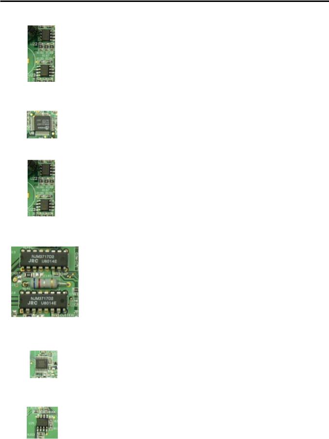
|
|
U22: DC/DC Converter |
|
|
|
|
|
|
|
|
|
|
|
|
|
|
|||||||||||||||||||||||||
|
|
|
|
|
|
|
|
|
|
|
|
|
|
|
|
|
|
|
|
|
|
|
|
|
|
|
|
|
|
|
|
|
|||||||||
|
|
|
|
|
|
|
|
|
|
|
|
|
|
|
|
|
|
|
|
|
|
|
|
|
|
|
|
|
|
|
|
|
|
|
|
||||||
|
|
|
|
|
|
|
|
|
|
|
|
|
|
|
|
|
|
|
|
|
|
|
|
|
|
|
|
|
|
|
|
|
|
U33: Regulator |
|||||||
|
|
|
|
|
|
|
|
|
|
|
|
|
|
|
|
|
|
|
|
|
|
|
|
|
|
|
|
|
|
|
|
|
|||||||||
|
|
|
|
|
|
|
|
|
|
|
|
|
|
|
|
|
|
|
|||||||||||||||||||||||
|
|
|
|
|
|
|
|
|
|
|
|
|
|
|
|
|
|
|
|
|
|
|
|
|
|||||||||||||||||
|
|
U23: DC/DC Converter |
|
|
|
|
|
|
|
|
|
|
|
|
|
|
|
|
|||||||||||||||||||||||
|
|
|
|
|
|
|
|
|
|
|
|
|
|
|
|
|
|
|
|
|
|
|
|
|
|
|
|
|
|
|
|
|
|
|
|||||||
|
|
|
|
|
|
|
|
|
|
|
|
|
|
|
|
|
|
|
|
|
|
|
|
|
|
|
U24: Regulator |
|
|
|
|||||||||||
|
|
|
|
|
|
|
|
|
|
|
|
|
|
|
|
|
|
|
|
|
|
|
|
|
|
|
|
|
|
|
|
|
|
|
|
|
|||||
|
|
|
|
|
|
|
|
|
|
|
|
|
|
|
|
|
|
|
|
|
|
|
|
|
|
|
|
||||||||||||||
U19: Stepping Motor Driver |
|
|
|
|
|
|
|
|
|
|
|
|
|
|
|
|
|
|
|
|
|
|
|
|
|
||||||||||||||||
|
|
|
|
|
|
|
|
|
|
|
|
|
|
|
|
|
|||||||||||||||||||||||||
|
|
|
|
|
|
|
|
|
|
|
|
|
|
|
|
|
|
|
|
|
|
|
|
|
|
|
|
|
|
|
|
|
|
|
|
|
|
|
|
|
|
U18: Stepping Motor Driver |
|
|
|
|
|
|
|
|
|
|
|
|
|
|
|
|
|
|
|
|
|
|
|
|
|
|
|
|
|||
|
|
|
|
|
|
|
|
|
|
|
|
|
|
|
|
||||||||||||||||
|
|
|
|
|
|
|
|
|
|
|
|
|
|
|
|
|
|
|
|
|
|
|
|
|
|
|
|
|
|
|
|
|
|
|
|
|
|
|
|
|
|
|
|
|
|
|
|
|
|
|
|
|
|
|
|
|
|
|
|
|
|
JP24: Thermistior |
|
|
JP14: Stepping Motor |
|
|
|
|
|
|
|
|
|
|
|
|
|
|
|
|
||||||||||||||
|
|
|
|
||||||||||||||||||||||||||||
|
|
|
|
|
|
|
|
|
|
|
|
|
|
|
|
|
|
|
|
|
|
|
|
|
|
|
|
|
|||
|
|
|
|
|
|
|
|
|
|
|
|
|
|
|
|
|
|
|
|
|
|
|
|
|
|
|
|
|
|
(Stepping Motor) |
|
|
|
|
|
|
|
|
|
|
|
|
|
|
|
|
|
|
|
|
|
|
|
|
|
|
|
|
|
|
|
|
|
|
|
|
|
|
|
|
|
|
|
|
|
|
|
|
|
|
|
|
|
|
|
|
|
|
|
|
|
|
|
||
|
|
|
|
|
|
|
JP35: Cutter Module |
|
|
|
|
|
|
|
|
|
JP20: Ribbon End Sensor |
|
|||||||||||||
|
|
|
|
|
|
|
|
|
|
|
|
|
|
|
|
|
|
||||||||||||||
|
|
|
|
|
|
|
|
|
|
|
|
|
|
|
|
|
|
|
|
|
|
|
|
|
|
|
|
(B-EV4T model) |
|
||
|
|
|
|
|
|
JP28: Feed Key/Status LED |
|
|
|
|
|
|
|
|
|
|
|
|
|
|
|
|
|
||||||||
|
|
|
|
|
|
|
|
|
|
|
|
|
|
|
|
|
|
|
|
|
|
|
|
|
|||||||
|
|
|
|
|
|
|
|
|
|
|
|
|
|
|
|
|
|||||||||||||||
|
|
|
|
|
|
|
|
|
|
|
|
|
|
|
|
|
|
|
|
|
|
|
|
|
|
|
|
||||
|
|
|
|
|
|
|
|
|
|
|
|
|
|
|
|
|
|
|
|
|
|
|
|
|
|
JP34: Feed Gap Sensor (Upper) |
|
||||
|
|
|
|
|
|
|
|
|
|
|
|
|
|
|
|
|
|
|
|
|
|
|
|
|
|
|
|||||
|
|
|
|
|
|
|
|
|
JP19: Strip Module |
|
|
|
|
|
|
|
|
|
|
|
|
|
|||||||||
|
|
|
|
|
|
|
|
|
|
|
|
|
|
|
|
|
|
|
|
|
|
|
|
|
|||||||
|
|
|
|
|
|
|
|
|
|
|
|
JP17: Black Mark Sensor |
|
||||||||||||||||||
|
|
|
|
|
|
|
|
|
|
|
|
|
|
|
|
|
|
|
|
|
|
|
|
||||||||
|
|
|
|
|
|
|
|
|
JP16: Cover Open Sensor |
|
|
|
|||||||||||||||||||
|
|
|
|
|
|
|
|
|
|
|
|
|
|
|
|
||||||||||||||||
|
|
|
|
|
|
|
|
|
|
|
|
|
JP29: Feed Gap Sensor (Lower) |
|
|||||||||||||||||
|
|
|
|
|
|
|
|
|
|
|
|
|
|
|
|
|
|
|
|
|
|
||||||||||
|
|
|
|
|
|
|
|
|
|
|
|
|
|
|
|
|
|
|
|
|
|
||||||||||
2-2
2. ELECTRONICS SPECIFICATIONS
EO18-33025
2.3 Description of the Main PC Board
2.3Description of the MAIN PC Board
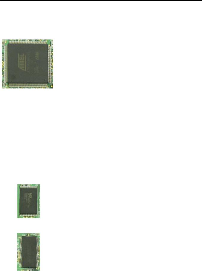
This PC board, the brain of the printer, is comprised of the following components.
32bit RISC CPU (U2): |
Type: AT91SAM9260 |
|
The 32bit RISC CPU operates the following processing: |
|
Controlling the interfaces |
|
• Serial Interface (RS-232C) |
|
• Parallel Interface (Centronics) |
|
• Eternet (10BASET/100BASETX) |
|
Controlling the Status LED |
|
Detect the [Feed] key |
|
Controlling the read/write operation on the memory |
|
• Flash ROM |
|
• SDRAM |
|
• SD Card |
|
Controlling the options |
|
• Cutter Module |
|
• Strip Module |
|
Control and detect sensor statuses |
|
• Ribbon Sensor |
|
• Cover Open Sensor |
|
• Feed Gap Sensor |
|
• Black Mark Sensor |
|
• Motor Temperature Thermistor |
|
Controlling the Print Head |
Flash ROM (U5): |
Type: MX29LV320CBTC-70G |
|
Capacity: 32M bit |
|
The programmed data of the boot program, main program, C/G, writable |
|
character are written into the flash ROM. |
SDRAM (U6): |
Type: IS42S16400B-6TL |
|
Capacity: 64M bit |
|
It is used for drawing the print data and used as a work area. |
2-3
2. ELECTRONICS SPECIFICATIONS
EO18-33025
2.3 Description of the Main PC Board
DC/DC Converter (U22, 23): |
Type: TS34063 |
|
It generates the voltages (+5V, +3.3V) from the power supply voltage |
|
(AC adapter). |
|
+5V and +3.3V are used as the operating voltage for each circuit. |
Eternet Transceiver (U8): |
Type: DM9161 |
|
This IC is used for controlling the Ethernet (10BASET/10BASETX). |
Regulator (U24, U33): |
Type: TS68N28CX5, TS9007DCX |
|
It generates the voltages (+1.8) from the DC/DC converter voltage |
|
(+3.3V). |
Stepping Motor Driver (U18, U19): Type: PBL3717
This IC is used for controlling the Stepping Motor.
Serial Interface Controller (U12): Type: SP3232ECY
This IC is used for controlling the Serial Interface (RS-232C).
Reset detect circuit (U25): |
Type: TS358 |
|
This IC is single supply dual operation amplifiers. |
|
It detects the voltage depression from +24V and +3.3V and outputs the |
|
Power Down signal to the CPU. |
2-4

2. ELECTRONICS SPECIFICATIONS
EO18-33025
2.3 Description of the Main PC Board
JP2 (SD Card Slot):
Signal |
Pin |
|
No. |
||
|
||
CD/DAT3 |
1 |
|
CMD |
2 |
|
VSS1 |
3 |
|
VDD |
4 |
|
CLK |
5 |
|
VSS2 |
6 |
|
DAT0 |
7 |
|
DAT1 |
8 |
|
DAT2 |
9 |
|
GND |
10 |
|
GND |
11 |
|
CD |
12 |
|
WP |
13 |
Type: MS3B11-KAA-0
This connector is connected to the SD Card.
Note: Recommended SD card specification.
•Supported DOS FAT file system.
•Folders stored in the SD card should be in the 8.3 filename format.
•Approved SD card manufacturers: SanDisk, Transcend.
SD V 1.0, V 1.1: 128MByte, 256MByte, 512MByte, 1GByte SD V 2.0 (SDHC): 4GByte Class 6
JP3 (Ethernet): |
|
Type: RJ45 with 2LEDs (Yellow and Green) |
|
|
|
|
This connector is used for the Ethernet (10BASET/100BASETX). |
|
Signal |
Pin |
|
|
|
||
|
No. |
|
|
|
|
|
|
|
Tx+ |
1 |
|
|
Tx- |
2 |
|
|
Rx+ |
3 |
|
|
N/C |
4 |
|
|
N/C |
5 |
|
|
Rx- |
6 |
|
|
N/C |
7 |
|
|
N/C |
8 |
|
|
Cathode of |
9 |
|
|
the Yelleo LED |
|
|
|
|
|
|
|
+3.3V (Anode of |
10 |
|
|
the Yellow LED |
|
|
|
|
|
|
|
Cathode of |
11 |
|
|
the Green LED |
|
|
|
|
|
|
|
+3.3V (Anode of |
12 |
|
|
the Green LED |
|
|
|
|
|
|
2-5
Loading...