


 Loading...
TOSHIBA Thermal Printer
B-852-R SERIES
 Maintenance Manual
Document No. EO18-33018
Original Mar., 2006
(Revised )
PRINTED IN JAPAN
EO18-33018
TABLE OF CONTENTS
|
|
|
Page |
1. |
UNPACKING -------------------------------------------------------------------------------------------- |
1- 1 |
|
|
1.1 |
PROCEDURES--------------------------------------------------------------------------------------------- |
1- 1 |
|
1.2 |
CHECKS ----------------------------------------------------------------------------------------------------- |
1- 2 |
2. |
MAJOR UNIT REPLACEMENT -------------------------------------------------------------------- |
2- 1 |
|
|
2.1 |
OPENING AND REMOVING THE COVERS ------------------------------------------------------- |
2- 1 |
|
2.2 |
LUBRICATION---------------------------------------------------------------------------------------------- |
2- 2 |
|
2.3 |
REPLACING THE CPU PC BOARD ------------------------------------------------------------------ |
2- 3 |
|
2.4 |
REPLACING THE PANEL PC BOARD--------------------------------------------------------------- |
2- 6 |
|
2.5 |
REPLACING THE STEPPING MOTOR-------------------------------------------------------------- |
2- 8 |
2.6REPLACING THE HEAD UP SENSOR, SLIT SENSOR (REWIND/FEED)
|
|
AND RIBBON MOTOR (REWIND/FEED) --------------------------------------------------------- |
2- 10 |
|
2.7 |
REPLACING THE PLATEN --------------------------------------------------------------------------- |
2- 14 |
|
2.8 |
REPLACING THE MEDIA SENSOR ---------------------------------------------------------------- |
2- 16 |
|
|
2.8.1 Feed Gap Sensor (TR) and Black Mark Sensor (Upper Side) ---------------------- |
2- 16 |
|
|
2.8.2 Feed Gap Sensor (LED) and Black Mark Sensor (Lower Side) -------------------- |
2- 17 |
|
2.9 |
REPLACING THE PRINT HEAD--------------------------------------------------------------------- |
2- 19 |
|
2.10 |
REPLACING THE PS UNIT AND REACTOR ---------------------------------------------------- |
2- 20 |
3. |
PERIODIC MAINTENANCE PROCEDURE............................................................................. |
3- 1 |
|
4. |
TROUBLESHOOTING ------------------------------------------------------------------------------------------- |
4- 1 |
|
CAUTION!
1.This manual may not be copied in whole or in part without prior written permission of TOSHIBA TEC.
2.The contents of this manual may be changed without notification.
3.Please refer to your local Authorised Service representative with regard to any queries you may have in this manual.
Copyright © 2006
by TOSHIBA TEC CORPORATION All Rights Reserved
570 Ohito, Izunokuni-shi, Shizuoka-ken, JAPAN

1. UNPACKING
EO18-33018
(Revision Date: Sep. 28, 2007
1.1 Procedure
1. UNPACKING
1.1 Procedure
1)Open the carton.
2)Unpack the accessories from the carton.
3)Unpack the pads and the printer from the carton.
|
Caution Label |
|
|
(QQ/QP model) |
|
|
Supply Holder |
|
Wing Bolt |
Frame (L) and (R) |
|
Print Head Cleaner |
Caution Label Instruction |
|
(QQ/QP model) |
||
|
Unpacking Instruction
Power Cord |
Supply Holder |
|
Base |
|
Owner’s Manual |
|
Supply Holder |
|
Pad A |
|
Top Pad |
Supply Holder Pad B |
|
 Cushion
Supply Holder
Unit
Cushion
Supply Holder Pad A
B-852-R Printer
Accessory Carton 
 Bottom Pad
 Carton
1- 1

1. UNPACKING
EO18-33018
(Revision Date: Sep. 28, 2007)
1.2 Checks
4) Remove the five pieces of tape from the printer. 5) Open the top cover.
6) Remove the one piece of tape.
Top Cover
Tape
Tape
Tape 
7)Press down the head block release lever (1) and raise the print head block (2).
8)Remove the print head pad (3).
Print Head Pad
|
|
Print Head Block |
|
2 |
1 |
|
|
|
3 |
|
Head Block Release Lever |
|
|
9)Place the printer on a level surface.
10)Please attach the supplied Caution Label to an easily visible position on the printer. (QQ/QP model)
CAUTION!
Do not use excessive force when closing the print head block,
as doing this may damage the gears. |
Print Head Block |
|
1.2 Checks
1)Check for damage or scratches on the machine.
2)Confirm that none of the accessories are missing.
NOTE: Keep the carton and pads for later transport.
1- 2
2. MAJOR UNIT REPLACEMENT
EO18-33018
2.1 OPENING AND REMOVING THE COVERS
2. MAJOR UNIT REPLACEMENT
WARNING!
Disconnect the power cord before replacing the parts.
2.1 OPENING AND REMOVING THE COVERS
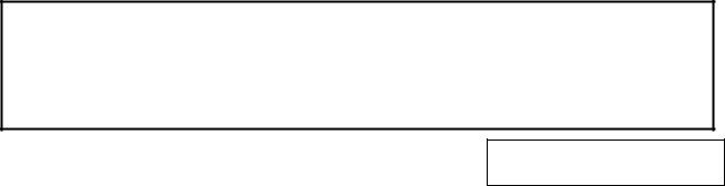
1)Turn the power off.
2)Open the top cover.
3)Remove the three B-4x6 screws to detach the side cover R.
B-4x6 Screw |
Top Cover |
B-4x6 Screw |
|
|
|
|
|
|
Side Cover R
NOTE: After removing the screws, unhook the side cover R from portion A by lifting and moving it toward the front of the printer.
Side Cover R
Portion A
Hook
4)Remove the two B-4x6 screws, PT-3x8 screw and D-4x6 screw to detach the side cover L.
Side Cover L |
D-4x6 Screw |
|
|
|
|
|
|
|
|
|
|
B-4x6 Screw |
TT-3x8 Screw |
2-1

2. MAJOR UNIT REPLACEMENT
EO18-33018
2.1 OPENING AND REMOVING THE COVERS
NOTE: After removing the screws, unhook the side cover L from portion B by lifting and moving it toward the front of the printer.
Hook
 Portion B
Side Cover L 
5)Disconnect the operation panel harness from CN13 on the MAIN PC Board.
Operation Panel Harness
CN13
MAIN PC
Board
NOTE: Instructions to open the top cover and to detach the side covers L and R are omitted from each removal/installation procedure provided below.
2.2 LUBRICATION
CAUTION!
1.Lubrication: During parts replacement
2.Kinds of oil: FLOIL G-488: 1 Kg can. (Parts No. 19454906001)
3.Do not spray the inside of the printer with lubricants. Unsuitable oil can damage the mechanism.
All machines are generally delivered in their best condition. Efforts should be made to keep them that way. Lack of oil, or the presence of debris or dust, may cause an unexpected failure. To maintain in optional operating condition, periodically clean the machine and apply the proper kind of oil to each part in which lubrication is needed.
Although the frequency of lubrication varies according to how often the machine is used, as a minimum it is necessary to lubricate before any part becomes dry. It is also necessary to wipe off excessive oil or it will collect dirt.
2-2

2. MAJOR UNIT REPLACEMENT
EO18-33018
2.3 Replacing the MAIN PC Board
2.3 Replacing the MAIN PC Board
1)Prior to replacing the MAIN PC board, print out the parameter settings for future reference.
2)Remove the side cover L from the printer. (Refer to Section 2.1.)
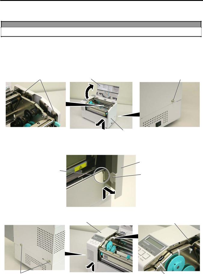
3)Remove the three SMW-3x6 screws to detach the rear frame cover.
SMW-3x6
Screw
Rear Frame Cover
4)Disconnect the harnesses from CN1, CN2, CN5, CN8, CN9 and CN500 on the MAIN PC board.
CN9 (Print Head Harness, Signal)
CN5 (Media Sensor Harness)
CN2 (Ribbon Motor Harness)
CN1 (Print Head Harness, Power)
MAIN PC Board |
CN500 (Stepping Motor Harness) |
|
2-3

2. MAJOR UNIT REPLACEMENT
EO18-33018
2.3 Replacing the MAIN PC Board
4)Remove the two SMW-4x8 screws, SMW-3x6 screw and B-3x6 screw.
SMW-4x8 Screw
MAIN PC Board Ass’y
B-3x6 Screw |
|
|
SMW-3x6 Screw |
|
|
|
|||
|
|
|
|
|
|
|
|
|
|
5)Disconnect the power harness from CN8 on the MAIN PC board ass’y, then remove the MAIN PC board ass’y from the printer.
Power Harness
MAIN PC Board Ass’y
CN8
2-4
2. MAJOR UNIT REPLACEMENT
EO18-33018
2.3 Replacing the MAIN PC Board
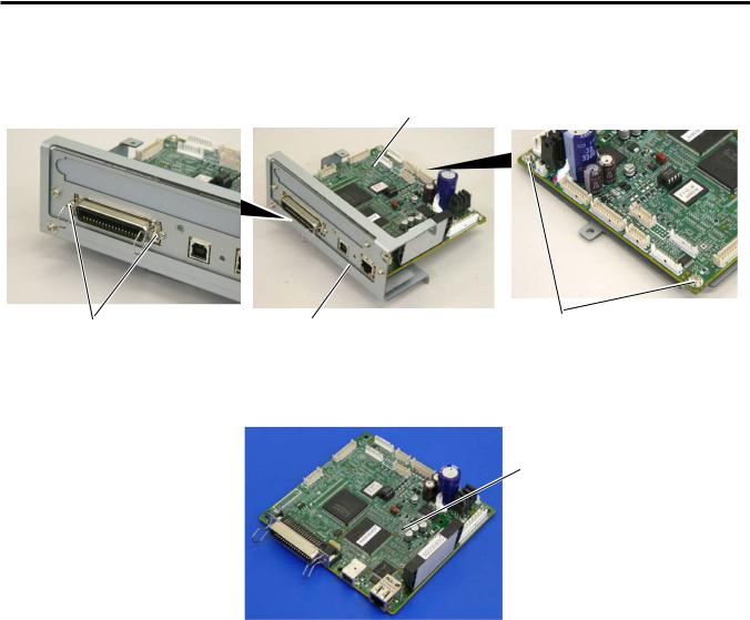
6)Remove the two B-3x6 screws and the two SMW-3x6 screws, then remove the MAIN PC board from the MAIN PCB support frame.
MAIN PC Board
|
|
|
|
MAIN PCB Support Frame |
SMW-3x6 |
B-3x6 Screw |
7)Replace the MAIN PC board with a new one, and reassemble in the reverse order of removal.
MAIN PC Board
8)After replacing the MAIN PC board, perform the following operations.
(1)Perform a RAM clear.
(2)Restore the printer system setting according to the printout of the parameter settings.
(3)Perform a media sensor adjustment.
(4)Perform a test print to print to confirm that the printer works properly.
2-5

2. MAJOR UNIT REPLACEMENT
EO18-33018
2.4 Replacing the Panel PC Board
2.4 Replacing the Panel PC Board
1)Remove the side cover L from the printer. (Refer to Section 2.1.)
2)Remove the PT-3x8 screw to detach the operation panel ass’y from the side cover L in the direction indicated by the arrow.
Side Cover L
Operation Panel Ass’y
PT-3x8 Screw
3)Disconnect the operation panel harness from CN2 on the panel PC board.
4)Disconnect the flat cable from CN3 on the panel PC board.
Operation Panel Harness |
Flat Cable |
CN2
CN3
2-6
Loading...