


 Loading...
Toshiba Personal Computer
Satellite A100/A105
TECRA A7
(PSAA8/PSAA9)
(PTA70/PTA71)
(PSAAx)
Maintenance Manual
TOSHIBA CORPORATION
S/ No.
Satellite A100/A105 / TECRA A7 Maintenance Manual

Copyright
© 2005 by Toshiba Corporation. All rights reserved. Under the copyright laws, this manual cannot be reproduced in any form without the prior written permission of Toshiba. No patent liability is assumed with respect to the use of the information contained herein.
Toshiba Satellite A100/A105 / TECRA A7 Maintenance Manual
First edition JAN. 2006
Disclaimer
The information presented in this manual has been reviewed and validated for accuracy. The included set of instructions and descriptions are accurate for the Satellite A100/A105 / TECRA A7 at the time of this manual's production. However, succeeding computers and manuals are subject to change without notice. Therefore, Toshiba assumes no liability for damages incurred directly or indirectly from errors, omissions, or discrepancies between any succeeding product and this manual.
Trademarks
Intel and Pentium are registered trademarks of Intel Corporation.
IBM, IBM PC/XT, PC/AT, PS/2 and OS/2 are registered trademarks of IBM Corporation. MS-DOS and Windows XP home edition are registered trademarks of Microsoft Corporation. Sound Blaster and Pro are trademarks of Creative Technology Ltd.
UNIX is a registered trademark of X/Open Company Ltd. NetWare are registered trademarks of Novell, Inc.
All other properties are trademarks or registered trademarks of their respective holders.
ii |
Satellite A100/A105 / TECRA A7 Maintenance Manual |
Preface
This maintenance manual describes how to perform hardware service maintenance for the Toshiba Personal Computer Satellite A100/A105 / TECRA A7, referred to as Satellite A100/A105 / TECRA A7 in this manual.
The procedures described in this manual are intended to help service technicians isolate faulty Field Replaceable Units (FRUs) and replace them in the field.
SAFETY PRECAUTIONS
Four types of messages are used in this manual to bring important information to your attention. Each of these messages will be italicized and identified as shown below.
DANGER: “Danger” indicates the existence of a hazard that could result in death or serious bodily injury, if the safety instruction is not observed.
WARNING: “Warning” indicates the existence of a hazard that could result in bodily injury, if the safety instruction is not observed.
CAUTION: “Caution” indicates the existence of a hazard that could result in property damage, if the safety instruction is not observed.
NOTE: “Note” contains general information that relates to your safe maintenance service.
Improper repair of the computer may result in safety hazards. Toshiba requires service technicians and authorized dealers or service providers to ensure the following safety precautions are adhered to strictly.
Be sure to fasten screws securely with the right screwdriver. If a screw is not fully fastened, it could come loose, creating a danger of a short circuit, which could cause overheating, smoke or fire.
If you replace the battery pack, RTC battery or backup battery, be sure to use only the same model battery or an equivalent battery recommended by Toshiba. Installation of the wrong battery can cause the battery to explode.
Satellite A100/A105 / TECRA A7 Maintenance Manual |
iii |

The manual is divided into the following parts:
Chapter 1 Hardware Overview describes the Satellite A100/A105 / TECRA A7 system unit and each FRU.
Chapter 2 Troubleshooting Procedures explains how to diagnose and resolve FRU problems.
Chapter 3 Test and Diagnostics describes how to perform test and diagnostic operations for maintenance service.
Chapter 4 Replacement Procedures describes the removal and replacement of the FRUs.
Appendices The appendices describe the following:
Handling the LCD module
Board layout
Keyboard scan/character codes
Key layout
Wiring diagrams
BIOS Rewrite Procedures
iv |
Satellite A100/A105 / TECRA A7 Maintenance Manual |

Conventions
This manual uses the following formats to describe, identify, and highlight terms and operating procedures.
Acronyms
On the first appearance and whenever necessary for clarification acronyms are enclosed in parentheses following their definition. For example:
Read Only Memory (ROM)
Keys
Keys are used in the text to describe many operations. The key top symbol as it appears on the keyboard is printed in boldface type.
Key operation
Some operations require you to simultaneously use two or more keys. We identify such operations by the key top symbols separated by a plus (+) sign. For example, Ctrl + Pause (Break) means you must hold down Ctrl and at the same time press Pause (Break). If three keys are used, hold down the first two and at the same time press the third.
User input
Text that you are instructed to type in is shown in the boldface type below:
DISKCOPY A: B:
The display
Text generated by the XXXXX that appears on its display is presented in the type face below:
Format complete
System transferred
Satellite A100/A105 / TECRA A7 Maintenance Manual |
v |

Table of Contents
Chapter 1 |
Hardware Overview |
|
|
1.1 |
Features................................................................................................................................ |
|
1 |
1.2 |
System Unit Components .................................................................................................... |
9 |
|
1.3 |
2.5-inch HDD..................................................................................................................... |
|
15 |
1.4 DVD-ROM Drive .............................................................................................................. |
16 |
||
1.5 CD-RW/DVD-ROM Drive................................................................................................ |
17 |
||
1.6 |
DVD Super Multi (+-R Double Layer).............................................................................. |
18 |
|
1.7 |
Power Supply..................................................................................................................... |
|
19 |
1.8 |
Batteries ............................................................................................................................. |
|
20 |
|
1.1.1 |
Main Battery........................................................................................... |
20 |
|
1.1.2 |
Battery Charging Control ....................................................................... |
20 |
|
1.1.3 |
RTC Battery ........................................................................................... |
21 |
Chapter 2 |
Troubleshooting |
|
||
2.1 |
Outline |
.................................................................................................................... |
|
2-1 |
2.2 |
Basic Flowchart...................................................................................................... |
2-2 |
||
2.3 |
Power Supply ......................................................................................................... |
|
2-6 |
|
|
Procedure 1 Power Icon Check........................................................................... |
2-6 |
||
|
Procedure 2 Connection Check........................................................................... |
2-8 |
||
|
Procedure 3 Replacement Check ........................................................................ |
2-8 |
||
2.4 |
System Board ......................................................................................................... |
|
2-9 |
|
|
Procedure ....................................................................3 |
Replacement Check |
2-10 |
|
2.5 |
2.5-inch .......................................................................................................HDD |
|
2-11 |
|
|
Procedure .............................................................................1 Message Check |
2-11 |
||
|
Procedure ......................................................................2 |
Partition Check |
2-11 |
|
|
Procedure ..........................................................................3 |
Format Check |
2-12 |
|
|
Procedure ...............................................................4 |
Test Program Check |
2-13 |
|
|
Procedure .............................5 |
Connector Check and Replacement Check |
2-14 |
|
|
|
|
|
|
vi |
|
|
Satellite A100/A105 / TECRA A7 Maintenance Manual |
|
2.6 |
Keyboard .............................................................................................................. |
|
2-15 |
|
Procedure 1 Test Program Check ...................................................................... |
2-15 |
|
|
Procedure 2 Connector Check and Replacement Check.................................... |
2-15 |
|
2.7 |
Display ................................................................................................................. |
|
2-16 |
|
Procedure 1 |
External Monitor Check ......................................................... |
2-16 |
|
Procedure 2 |
Test Program Check ............................................................... |
2-16 |
|
Procedure 3 |
Connector Check and Replacement Check............................. |
2-16 |
2.8 |
ODD (Optical Disk Drive) ................................................................................... |
2-18 |
|
|
Procedure 1 |
ODD Cleaning Check ............................................................. |
2-18 |
|
Procedure 2 |
Test Program Check ............................................................... |
2-18 |
|
Procedure 3 |
Connector Check and Replacement Check............................. |
2-18 |
2.9 |
LAN...................................................................................................................... |
|
2-20 |
|
Procedure 1 |
Test Program Check ............................................................... |
2-20 |
|
Procedure 2 |
Connector Check and Replacement Check............................. |
2-20 |
2.10 |
SD/MS/MS pro/MMC/XD Card(Optional) ......................................................... |
2-21 |
|
|
Procedure 1 |
Test Program Check ............................................................... |
2-21 |
|
Procedure 2 |
Connector Check .................................................................... |
2-21 |
2.11 |
Finger Print(Optional) .......................................................................................... |
2-22 |
|
|
Procedure 1 |
Test Program Check ............................................................... |
2-22 |
|
Procedure 2 |
Connector Check .................................................................... |
2-22 |
2.12 |
3D Sensor ............................................................................................................. |
|
2-23 |
|
Procedure 1 |
Test Program Check ............................................................... |
2-23 |
|
Procedure 2 |
Replacement Check ................................................................ |
2-23 |
2.13 |
Parallel Port(Optional) ......................................................................................... |
2-24 |
|
|
Procedure 1 |
Test Program Check ............................................................... |
2-24 |
|
Procedure 2 |
Connector Check .................................................................... |
2-24 |
2.14 |
Audio Test ............................................................................................................ |
|
2-25 |
|
Procedure 1 Test Program Check ...................................................................... |
2-25 |
|
|
Procedure 2 Connector Check and Replacement Check.................................... |
2-25 |
|
2.15 |
IEEE 1394 Test .................................................................................................... |
|
2-26 |
|
Procedure 1 |
Test Program Check ............................................................... |
2-26 |
|
Procedure 2 |
Connector Check .................................................................... |
2-26 |
|
|
||
Satellite A100/A105 / TECRA A7 Maintenance Manual |
vii |
||

2.16 |
Cooling Module |
.................................................................................................... |
2-27 |
|
Procedure 1 ............................................................... |
Test Program Check |
2-27 |
|
Procedure 2 ............................. |
Connector Check and Replacement Check |
2-27 |
Chapter 3 |
Diagnostic Programs |
|
|
3.1 |
General |
|
1 |
3.2 |
Quick Start.................................................................................................................. |
|
3 |
|
3.2.1 ................................................................................................ |
Quick Test |
3 |
|
3.2.2 ................................................................................... |
Customization Test |
3 |
|
3.2.3 ............................................................................... |
Keyboard Layout test |
7 |
|
3.2.4 .............................................................................................. |
Hotkey Test |
8 |
|
3.2.5 ........................................................................................ |
Audio Play Test |
8 |
|
3.2.6 ................................................................................... |
Audio Record Test |
8 |
|
3.2.7 ................................................................................................. |
DMI Read |
8 |
|
3.2.8 ................................................................................................ |
DMI Write |
9 |
|
3.2.9 ....................................................................................... |
3D Sensor Test |
10 |
|
3.2.10 ............................................................................................. |
FPRD Test |
16 |
|
3.2.11 ............................................................................................. |
FENR Test |
16 |
|
3.2.12 ............................................................................ |
IrDA ManMaster Test |
16 |
|
3.2.13 .............................................................................. |
IrDA ManSlave Test |
17 |
|
3.2.14 ................................................................................ |
System Information |
17 |
|
3.2.15 .............................................................................................. |
View Logs |
19 |
|
3.2.16 ..................................................................................... |
Exit to MS DOS |
19 |
|
3.2.17 ...................................................... |
The Diagnostics Screen Explanation |
19 |
3.3 |
Options ..................................................................................................................... |
|
23 |
|
3.3.1 ................................................................................................ |
Overview |
23 |
|
3.3.2 ............................................................ |
Batch Parameters Configuration |
24 |
|
3.3.3 ........................................................... |
Item’s Parameters Configuration |
26 |
|
3.3.4 ........................................................................... |
Load Batch Parameters |
27 |
|
3.3.5 ........................................................................... |
Save Batch Parameters |
28 |
|
3.3.6 ......................................................................... |
LOG Parameters Setting |
28 |
|
3.3.7 .............................................................................. |
Specify LOG Viewer |
29 |
viii |
Satellite A100/A105 / TECRA A7 Maintenance Manual |

|
3.3.8 |
Display LOG File .................................................................................. |
30 |
|
3.3.9 |
LOG Viewer .......................................................................................... |
30 |
|
3.3.10 |
LOG File Sample................................................................................... |
32 |
3.4 |
Subtests.................................................................................................................... |
|
33 |
3.5 |
System Test ............................................................................................................. |
36 |
|
3.6 |
Memory Test ........................................................................................................... |
40 |
|
3.7 |
Storage..................................................................................................................... |
|
46 |
3.8 |
Video ....................................................................................................................... |
|
50 |
3.9 |
Communication (COMM)....................................................................................... |
59 |
|
3.10 |
Peripheral ................................................................................................................ |
|
61 |
3.11 |
Error Codes and description.................................................................................... |
63 |
|
3.12 |
Quick Test Item List................................................................................................... |
i |
|
Satellite A100/A105 / TECRA A7 Maintenance Manual |
ix |

Chapter 4 |
Replacement Procedures |
|
|
4.1 |
General |
................................................................................................................... |
4-1 |
|
Safety Precautions................................................................................................ |
4-2 |
|
|
Before ................................................................................................You Begin |
4-4 |
|
|
Disassembly ......................................................................................Procedures |
4-5 |
|
|
Assembly ...........................................................................................Procedures |
4-5 |
|
|
Tools and ...........................................................................................Equipment |
4-6 |
|
|
Screw ....................................................................................Tightening Torque |
4-6 |
|
|
Colors .......................................................................................of Screw Shanks |
4-7 |
|
|
Symbols .........................................................of Screws on the Computer Body |
4-7 |
|
|
Symbol .................................................................................................examples |
4-7 |
|
|
Removing .................................................................................the Battery Pack |
4-8 |
|
|
Installing ...................................................................................the Battery Pack |
4-9 |
|
|
Removing ......................................................................the PCI Expresss Card |
4-10 |
|
|
Installing .......................................................................the PCI Expresss Card |
4-11 |
|
|
Removing .......................................................................the Optional PC Card |
4-12 |
|
|
Installing .........................................................................the Optional PC Card |
4-13 |
|
|
Removing .............................................................................the Momery Card |
4-14 |
|
|
Installing ...............................................................................the Momery Card |
4-15 |
|
|
Removing .......................................................................the Optional Memory |
4-16 |
|
|
Installing .........................................................................the Optional Memory |
4-18 |
|
|
Removing ..................................................................................the MDC Card |
4-19 |
|
|
Installing ....................................................................................the MDC Card |
4-21 |
|
4.2 |
HDD ..................................................................................................................... |
|
4-22 |
|
Removing ...........................................................................................the HDD |
4-22 |
|
|
Installing .............................................................................................the HDD |
4-24 |
|
4.3 |
Speaker ...............................................................................Cover and Keyboard |
4-24 |
|
|
Removing .....................................................the Speaker Cover and Keyboard |
4-25 |
|
|
Installing ......................................................the Speaker Cover and Keyboard |
4-26 |
|
4.4 |
Bluetooth .....................................................................................................Card |
4-27 |
|
|
Removing ...........................................................................the Bluetooth Card |
4-27 |
|
x |
Satellite A100/A105 / TECRA A7 Maintenance Manual |
|
Installing the Bluetooth Card............................................................................. |
4-28 |
4.5 |
Wireless LAN Card.............................................................................................. |
4-29 |
|
Removing the Wireless LAN Card .................................................................... |
4-29 |
|
Installing the Wireless LAN Card...................................................................... |
4-30 |
4.6 |
ODD Bay Module ................................................................................................ |
4-31 |
|
Removing the ODD Bay Module ...................................................................... |
4-31 |
|
Installing the ODD Bay Module........................................................................ |
4-32 |
|
Disassembling the ODD Bay Module................................................................ |
4-33 |
|
Assembling the ODD Bay Module .................................................................... |
4-33 |
4.7 |
Display Assembly ..................................................................................................... |
4-34 |
|
Removing the Display Assembly....................................................................... |
4-34 |
|
Installing the Display Assembly ........................................................................ |
4-35 |
4.8 |
Top Cover............................................................................................................. |
4-36 |
|
Removing the Top Cover................................................................................... |
4-36 |
|
Installing the Top Cover .................................................................................... |
4-38 |
4.9 |
CPU Cooling Module and Fan ............................................................................. |
4-39 |
|
Removing the CPU Cooling and Fan (for VGA Card Model) .......................... |
4-39 |
|
Installing the CPU Cooling and Fan (for VGA Card Model)............................ |
4-41 |
|
Removing the CPU Cooling and Fan................................................................. |
4-42 |
|
Installing the CPU Cooling and Fan .................................................................. |
4-43 |
4.10 |
VGA Card (for VGA Card Model Only) ............................................................. |
4-44 |
|
Removing the VGA Card................................................................................... |
4-44 |
|
Installing the VGA Card .................................................................................... |
4-45 |
4.11 |
CPU ...................................................................................................................... |
4-46 |
|
Removing the CPU ............................................................................................ |
4-46 |
|
Installing the CPU.............................................................................................. |
4-47 |
4.12 |
USB Board, Finger Print Board and Print Board ................................................. |
4-49 |
|
Removing the USB Board, Finger Print Board and Print Board ....................... |
4-49 |
|
Installing the USB Board, Finger Print Board and Print Board......................... |
4-50 |
4.13 |
System Board, MIC cable, AC IN cable .............................................................. |
4-51 |
|
Removing the System Board, MIC cable, AC IN cable…. ............................... 4-51 |
|
|
|
|
Satellite A100/A105 / TECRA A7 Maintenance Manual |
xi |
|

|
Installing the System Board, MIC cable, AC IN cable….................................. 4-52 |
|
4.14 |
Display Mask........................................................................................................ |
4-53 |
|
Removing the 15.4-inch LCD Display Mask .................................................... |
4-53 |
|
Installing the 15.4-inch LCD Display Mask...................................................... |
4-54 |
4.15 |
FL Inverter Board................................................................................................. |
4-55 |
|
Removing the FL Inverter Board....................................................................... |
4-55 |
|
Installing the FL Inverter Board ........................................................................ |
4-56 |
4.16 |
LCD Modules....................................................................................................... |
4-57 |
|
Removing the 15.4-inch LCD module............................................................... |
4-57 |
|
Installing the 15.4-inch LCD Module................................................................ |
4-59 |
4.17 |
Speakers ............................................................................................................... |
4-60 |
|
Removing the Speakers...................................................................................... |
4-60 |
|
Installing the Speakers ....................................................................................... |
4-60 |
4.18 |
Switch Cover and Switch Board .......................................................................... |
4-61 |
|
Removing the Switch Cover and Switch Board (For Consumer Model) .......... |
4-61 |
|
Installing the Switch Cover and Switch Board.................................................. |
4-62 |
|
Removing the Switch Cover and Switch Board (For Commercial Model)....... |
4-63 |
|
Installing the Switch Cover and Switch Board.................................................. |
4-64 |
4.19 |
Touch Pad and Touch Pad Board ........................................................................ |
4-65 |
|
Removing the Touch Pad and Touch Pad Board (For Consumer Model)......... |
4-65 |
|
Installing the Touch Pad and Touch Pad Board ................................................ |
4-66 |
|
Removing the Touch Pad and Touch Pad Board (For Commercial Model)...... |
4-67 |
|
Installing the Touch Pad and Touch Pad Board ................................................ |
4-68 |
xii |
Satellite A100/A105 / TECRA A7 Maintenance Manual |

Appendices |
|
|
Appendix A |
Handling the LCD Module ........................................................................... |
A-1 |
Appendix B |
Board Layout ................................................................................................ |
B-1 |
Appendix C |
Keyboard Scan/Character Codes .................................................................. |
C-1 |
Appendix D |
Key Layout.................................................................................................... |
D-1 |
Appendix E |
Wiring Diagrams............................................................................................ |
E-1 |
Appendix F |
BIOS Rewrite Procedures.............................................................................. |
F-1 |
Appendix G |
EC/KBC Rewrite Procedures........................................................................ |
G-1 |
Appendix H |
GREASE NFORMATION ………………………..………………………H-1 |
|
Satellite A100/A105 / TECRA A7 Maintenance Manual |
xiii |

Chapter 1
Hardware Overview

1 Hardware Overview
ii |
Satellite A100/A105 / TECRA A7 Maintenance Manual |

1 Hardware Overview
Chapter 1 |
Contents |
|
|
1.1 |
Features ............................................................................................................................... |
|
1 |
1.2 |
System Unit Components ................................................................................................... |
9 |
|
1.3 |
2.5-inch HDD.................................................................................................................... |
|
15 |
1.4 DVD-ROM Drive ............................................................................................................. |
16 |
||
1.5 CD-RW/DVD-ROM Drive............................................................................................... |
17 |
||
1.6 |
DVD Super Multi (+-R Double Layer)............................................................................. |
18 |
|
1.7 |
Power Supply .................................................................................................................... |
|
19 |
1.8 |
Batteries ............................................................................................................................ |
|
20 |
|
1.1.1 |
Main Battery.......................................................................................... |
20 |
|
1.1.2 |
Battery Charging Control ...................................................................... |
20 |
|
1.1.3 |
RTC Battery .......................................................................................... |
21 |
Satellite A100/A105 / TECRA A7 Maintenance Manual |
iii |

1 Hardware Overview
Figures |
|
|
Figure 1- 1 |
id Parts description placement |
..............................................................................6 |
Figure 1- 2 The computer Block diagram ................................................................................ |
7 |
|
Figure 1- 3 |
System Board configuration ................................................................................. |
8 |
Figure 1- 4 |
System unit block diagram .................................................................................... |
9 |
Figure 1- 5 |
2.5-inch HDD ..................................................................................................... |
15 |
Figure 1- 6 |
DVD-ROM drive ................................................................................................ |
16 |
Tables |
|
|
Table 1- 1 2.5-inch HDD specifications................................................................................ |
15 |
|
Table 1- 2 DVD-ROM drive specifications .......................................................................... |
16 |
|
Table 1- 3 CD-RW/DVD-ROM drive specifications............................................................ |
17 |
|
Table 1- 4 |
DVD Super Multi drive (+-R Double Layer) specifications ............................... |
18 |
Table 1- 5 |
Battery specifications........................................................................................... |
20 |
Table 1-6 Quick/normal charging time ................................................................................. |
21 |
|
iv |
Satellite A100/A105 / TECRA A7 Maintenance Manual |

1.1 Features |
1 Hardware Overview |
1.1 Features
The Toshiba Satellite A100/A105 / TECRA A7 is a full size notebook PC based on the Intel Pentinm M (Dothan) and Celeron M processor, providing high-speed processing capabilities and advanced features. The computer employs a Lithium Ion battery that allows it to be batteryoperated for a longer period of time. The display uses 15.4-inch WXGA and WSXGA+ LCD panel, at a resolution of 1280 by 800 pixels (WXGA) and 1680 by 1050 pixels (WSXGA+), The uPGA socket supports BTO/CTO for the CPU so that the system can be designed to suit your needs.
The computer has the following features.
Processor
The CPU is the Intel Yonah Processor and Intel Yonah based Celeron M.
Intel Yonah Processor (667MHz)
T2300(1.66G)/T2400(1.83G)/T2500(2G)/T2600(2.16G)/T2700(2.33G)
/T1300(1.66G)/T1400(1.83G) Hz
Intel Yonah based Celeron M Processor (533MHz) 410/420/430
Host bridge system controller
System controller: Intel 945GM/945PM/940GML
Memory
The computer has two SO DIMMs slot comes standard with DDRII 4200 module. It supports PC2-4200 and uses SO DIMMs (DDRII SDRAM) driven at 1.8 V, accepting BTO/CTO for your memory requirements. It can incorporate up to 4 GB of main memory.
using the following sizes of memory modules:
y256 MB (16M×16×8P)/533/667 MHZ
y512 MB (32M×16×8P)/533/667 MHZ
y1024 MB (64Mx16x8P)/533/667 MHZ
Satellite A100/A105 / TECRA A7 Maintenance Manual |
1 |

1 Hardware Overview |
1.1 Features |
Hard Disk Drive (HDD)
The computer accommodates one 2.5-inch HDD with any of the following storage capacities:
y40 GB (9.5 mm thick) SATA (5,400rpm)
y60 GB (9.5 mm thick) SATA (5,400rpm/7200rpm)
y80 GB (9.5 mm thick) SATA (5,400rpm/7200rpm)
y100 GB (9.5 mm thick) SATA (5,400rpm/7200rpm)
y120 GB (9.5 mm thick) SATA (5400rpm)
ODD
The ODD can accommodate a DVD-ROM, CD-RW/DVD ROM, DVD Super Multi (+-R Double Layer)drives.
Display
The LCD displays available come in the following four sizes:
y15.4” WXGA-Non CSV/15.4” WXGA-CSV/15.4” WXGA-CSV(200 NITs High
brightness) /15.4” WXGA-HHCSV(490 NITs High brightness) color display, resolution 1280×800,262,144 colors with dithering.
y
Keyboard
The keyboard has 29 kinds countries key.
Batteries
The computer has a removable 6/9/12 Cell Lithium Ion battery pack and an internal RTC battery (rechargeable).
Universal Serial Bus (USB) ports
The computer has four USB 2.0 ports, It is supported to daisy-chain a maximum of 127 USB devices. The serial data transfer rate is 480 Mbps or 12 Mbps and 1.5 Mbps These ports support PnP installation and hot plugging.
2 |
Satellite A100/A105 / TECRA A7 Maintenance Manual |

1.1 Features |
1 Hardware Overview |
External monitor port
A 15-pin external monitor port is provided, through which the computer automatically recognizes an external VESA DDC 2B compatible monitor.
PC Card slot
A PC Card slot is provided to hold PC Card Standard Type II (5.0 mm) card, capable of using a variety of PC Cards including 16-bit Multiple Function PC Cards and 32-bit CardBus cards.
PC card HDD boot does Not be supported.
SD/MS/MS Pro/MMC/XD Card slot(BTO)
This slot is for your memory card requirements to provide memory card read on your computer
Toshiba Pointing Device(BTO)
Toshiba Pointing Device has one kind of Synaptice TouchPad with two button and One kind of Dual mode Pad for BTO .
Sound system
The ALC861 integrated audio controller supports multimedia. The sound system contains the following:
yStereo speakers
yHeadphone jack
yInternal microphone
yExternal microphone jack
LAN
The internal LAN board supports 10/100 Mbit and Giga-bit for BTO, enabling connection to a LAN at up to 1GMbps. It also supports Wake-up On LAN From S3/S4/S5 and PXE boot support. The LAN board has the RJ45 jack to directly accommodate a LAN cable.
Satellite A100/A105 / TECRA A7 Maintenance Manual |
3 |
1 Hardware Overview |
1.1 Features |
Wireless LAN
The internal Mini Card slot supports IEEE802.11a/g(11ch)/ IEEE802.11g(11ch)/ IEEE802.11a/g(13ch)/ IEEE802.11g(13ch)/IEEE802.11a/g(14ch)/ IEEE802.11g(14ch) card. The Antenna has three wires dual band antenna support with Blue tooth for BTO.
Internal Modem
The computer contains a MDC, enabling data and fax communication. It supports ITU- T V.90 (for rest countries )/V.92(America, Canada,UK,Germany,France) The transfer rates are 56 Kbps for data reception, 33.6 Kbps for data transmission, and 14,400 bps for fax transmission. Note, however, that the actual speed depends on the line quality. The RJ11 modem jack is used to accommodate a telephone line.
IEEE 1394(BTO)
The IEEE 1394 serial data transfer rate is 400 Mbps, These port support hot plugging.
Finger Print(BTO)
This product has a fingerprint utility installed for the purpose of enrolling and recognizing fingerprints. By enrolling the ID and password to the fingerprint authentication device, it is no longer necessary to input the password from the keyboard. Just by swiping the finger against the fingerprint sensor.
TPM 1.2
The Trusted Platform Module (TPM) is an integrated circuit and software platform that provides computer manufacturers with the core components of a subsystem used to assure authenticity, integrity and confidentiality in e-commerce transactions and Internet communications.
CD Key(BTO)
The CD Key supports to play Audio CD directly.
PCI Express Slot(BTO)
4 |
Satellite A100/A105 / TECRA A7 Maintenance Manual |

1.1 Features |
1 Hardware Overview |
The ICH7 provides PCI Express root ports which are compliant to the PCI Express Base Specification ,Revision 1.0a.The Root Port supports 2.5Gb/s bandwidth in each direction (5 Gb/s concurrent) and two virtual channels for full isochronous data support.
Parallel Port(BTO)
The Parallel Port is optional integrated device. to supported connect a printer or another parallel device. The port is IEEE-1284 compliant and supports Extended Capabilities Port (ECP).
Fast Serial Infrared (FIR) communications port(BTO)
The FIR Port is optional integrated device. It provided an IrDA 1.1 compatible FIR port , enabling wireless communication at a high speed of 1.15 or 4 Mbps.
Satellite A100/A105 / TECRA A7 Maintenance Manual |
5 |

1 Hardware Overview |
1.1 Features |
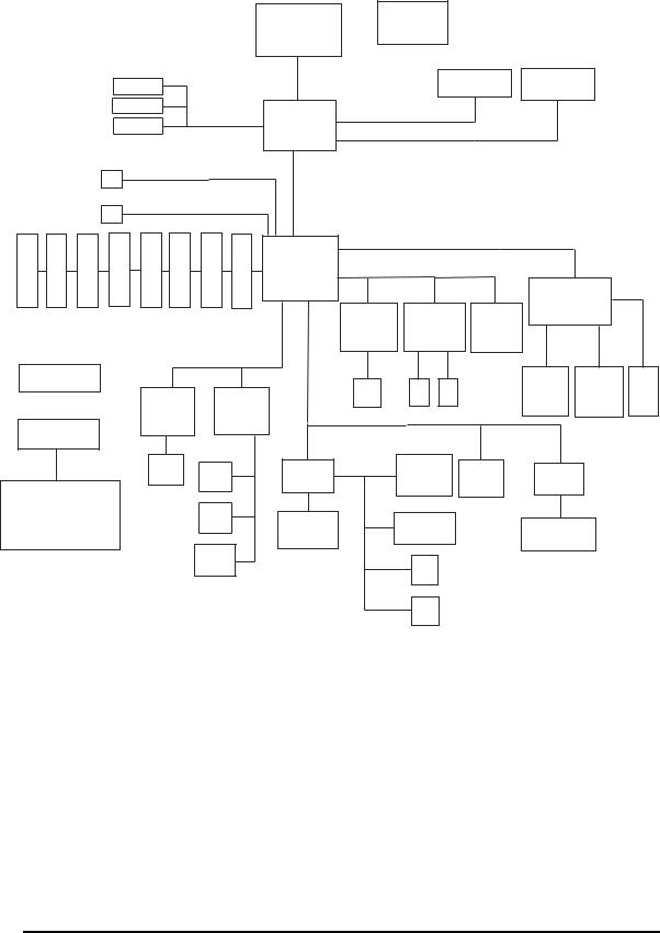
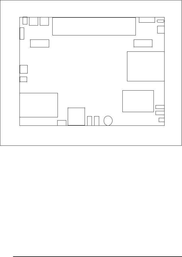
Figures 1-1/1-2/1-3 and 1-4 show the computer and its system unit configuration, respectively.
Figure 1- 1 id Parts description placement
6 |
Satellite A100/A105 / TECRA A7 Maintenance Manual |
1.1 Features |
1 Hardware Overview |
|
Yonah |
|
ICS9LP306 |
|
|
|
Clock generator |
|
|
|
(uFCPGA) |
|
|
|
|
|
|
|
|
S-video |
FSB,533/667MHz |
DDR2_SODIMM0 |
DDR2_SODIMM1 |
|
|
|
|||
LCM |
Calistoga |
1.8V,DDR2Interface,533/667MHz |
|
|
CRT |
|
|||
945GM/PM |
|
|
|
|
|
1466 uFCBGA |
1.8V,DDR2Interface,533/667MHz |
|
|
|
HDD |
SATA |
|
DMIx4 |
|
|
|
|
|
ODD |
Primary_IDE |
|
|
|
N |
N |
B |
B |
4 |
5 |
Card |
7BS |
ICH7-M |
SB |
SB |
S |
S |
oth |
6BS |
652 BGA |
||
O |
O |
O |
O |
BS |
BS |
ress |
CKING |
|
A |
B |
C |
D |
|
|
|
|
|
0 |
1 |
2 |
3 |
|
|
|
|
|
N |
N |
Blueto |
FINGER |
Exp |
DO |
|
||
C |
C |
C |
C |
|
||||
N |
N |
N |
N |
|
|
|
|
|
U |
U |
U |
U |
U |
U |
U |
U |
|
|
|
|
|
MDC/Modem |
|
AZALIA |
Interface,33MHz |
|
|
|
|
|
|
|
|
3.3V,AZALIA |
|
PORTREPLICATOR |
|
|
|
|
|
3.3V,LPC_ |
||
|
|
|
|
Module56K |
|
|
||
|
|
|
|
|
|
|
||
BATTERY
3.3V,PCI_Interface,33MHz
PCI_EXPRESS
|
|
|
CARD BUS |
|
|
INTEL |
|
|
TI_PCI7412/4512 |
|
|
MINI CARD |
|
(CO-LAYOUT) |
|
||
10/10082562GZ |
EXPRESSCARD |
|
|||
1G82573E(ATM) |
Wireless LAN |
|
|
|
|
82573L(w/oATM) |
|
|
|
|
|
RJ45 |
ANT ANT |
|
Cardbus |
Card reader |
1394 |
|
SLOTA |
CONN |
CONN |
||
|
RJ11 |
MIC |
SMSC |
3-AXISSENSOR TPM 1.2 |
SMSC |
|
|
KBC1100 |
|||
System Charger& |
|
JACK |
|
SIO 1036 |
|
|
|
|
|
|
|
DC/DC System power |
|
HP |
|
SERIALPORT |
|
(IMVP-6 VR) |
|
JACK |
BIOS |
PARALLEL PORT |
|
|
|
FLASH ROM |
|
||
|
|
|
|
|
SPEAKER
FIR
CIR
Figure 1- 2 The computer Block diagram
Satellite A100/A105 / TECRA A7 Maintenance Manual |
7 |
1.1 Features |
1 Hardware Overview |
DC- I NRj 45USB*2 |
|
Par al l el |
Kensi - |
Battery |
|
||
|
Rj 11 |
||
|
|
|
ngt on |
RGB |
|
|
|
Speaker |
|
Speaker |
|
S-Vi deo |
|
ODD |
|
|
|
|
|
1394 |
|
|
|
PC Card*1 |
|
HDD |
|
Express Card *1 |
Vol ume |
USB*2 |
|
5 i n 1 |
|
|
|
|
|
|
|
Car d |
|
|
Ki l l SW |
Reader |
|
|
|
FI R/ CI R |
Mi crophone |
|
|
|
Headphone |
|
|
Figure 1- 3 System Board configuration
Satellite A100/A105 / TECRA A7 Maintenance Manual |
8 |

1.2 System Unit Components |
1 Hardware Overview |
1.2 System Unit Components
Figure 1-4 is a block diagram of the system unit.
Max 6657
Themal Sensor
Pc4200 DDRI I
533/ 667 Mhz
Expansi on Memor y
256/ 512/ 1024
Expansi on Memor y
256/ 512/ 1024
I nt - HDD
SATA SATA 40120GB
9. 5mm
DVDROM
DVDCD/ RWCOMBO DVD Super Mul t i
( +- R Doubl e l ayer )
CPU : I nt el |
Cl ock Gener at or |
|
|
Yonah |
( I CS9LP306) |
|
|
1. 66G. . . . . . 2. 33GHZ |
|
I SL6218 |
DC |
uPGA |
CPU V I D |
||
|
|
|
|
|
|
|
S- Vi deo |
I nt el |
|
LVDS |
LCD 15. 4" |
945GM/ PM |
|
|
|
940GML |
|
|
CRT |
Nor t h Br i dge |
|
|
VRAM |
|
|
|
|
DMI |
|
|
|
SM Bus
Cont .
I CH7- M
Sout h Br i dge
Ac97
I DE
Cont .
USB
Cont . ( 02)
PCI - PC
Br i dge
LAN |
|
Mi ni |
CARD BUS |
|
Cont . |
|
|
||
10/ 100 |
|
PCI Sl ot |
Cont r ol l er |
|
82562GZ |
802. 11g, a/ g |
TI _PCI 7412 |
||
1G |
|
/ PCI 4512 |
|
|
|
Wi r el ess |
|
||
82573E |
|
|
|
|
|
|
Lan |
|
|
EEPROM |
|
Ant enna |
PCMCI A |
5i n1 |
|
|
|
|
Car d |
|
Rj 45 |
|
Reader |
|
|
|
|
||
|
|
MDC |
Rj 11 |
|
|
|
Modem |
|
|
|
|
|
|
|
|
|
CODEC |
TPA6011 |
|
|
|
ALC 861 |
||
1394
CNNx1
Speaker
MI C
Headphone
USB
USB
USB
I nt er nal LPC
Fl ash |
EC/ KBC |
|
3- AXI S |
TPM |
SMSC |
ROM |
( KBC1100) |
|
SENSOR |
1. 2 |
SI O 1036 |
|
|
|
SERI AL |
|
|
|
|
I 2C |
PORT |
|
|
St i ck poi nt |
|
|
|
|
PARALLEL |
K/ B |
|
Mai n Bat t er y |
FI R |
|
PORT |
|
|
|
|
||
|
KPA AC |
EEPROM |
|
|
|
|
1269A |
CI R |
|
|
|
|
|
|
|
|
Figure 1- 4 System unit block diagram
Satellite A100/A105 / TECRA A7 Maintenance Manual |
9 |

1 Hardware Overview |
1.2 System Unit Components |
The system unit of the computer consists of the following components:
Processor: Intel Yonah Processor and Yonah Based Celeron M
yIntel Yonah Processor (667MHz)
−Core speed: 1.66/1.83/2.0/2.16/2.33 GHz
−System bus: 667 MHz
−On-die level 2 cache 2 MB
−Advanced Power Management features including Enhanced Intel ® SpeedStep ® technology
yYonah Based Celeron-M (533MHz)
−Core speed: TBD
−System bus: 533 MHz
−On-die level 2 cache 1 MB
Memory
Two expansion memory slots were provided, They can hold 256/512/1024MB expansion memory modules available as options to grow up to 4.0 GB.
yPC2-4200 /533/667MHz DDRII SDRAM supported
y256/512/1024MB modules supported
−256 MB (16M x 16 x 8P)
−512 MB (32M x 16 x 8P)
−1024 MB (64M x 8 x 16P)
y1.8 volt operation
yNo parity bit
y64-bit data transfer
10 |
Satellite A100/A105 / TECRA A7 Maintenance Manual |

1.2 System Unit Components |
1 Hardware Overview |
BIOS ROM (flash EEPROM)
y8Mb x 1 chip (1024KB flash parts)
−40Kb used for EC BIOS
−35Kb used for PNP
−3Kb used for display
−15Kb used for logo
−16Kb used for setup
−10Kb used for setup nodes
−1Kb used for decompress code
−1Kb used for boot block
−2Kb used for TPM
−64Kb used for
−23Kb used for miser
−237Kb used for VGA BIOS
−42Kb used for PXE
−14Kb used for string
−47Kb used for ROMEXEC
−133Kb used for BIOS code
−6Kb used for mini loader
System controllers
yNorth Bridge: Intel 945 GM/PM/940GML
−CPU interface and control
−System Memory Support
−PCI Express* Graphics (PEG) Interface
−Integrated Display Interface Support
−Internal Graphics Features
−Direct Media Interface (DMI)
−Power Management
−Serial ATA Interface
−ICH7 Audio Control
−SMBus 2.0/SMLink Interface
ySouth Bridge: ICH7-M
−Direct Media Interface (DMI)
−PCI Express* Interface
−Serial ATA (SATA) Controller
Satellite A100/A105 / TECRA A7 Maintenance Manual |
11 |

1 Hardware Overview |
1.2 System Unit Components |
−Advanced Host Controller Interface (AHCI)
−PCI Interface
−IDE Interface
−Low Pin Count (LPC) Interface
−Compatibility Modules
−Advanced Programmable Interrupt Controller (APIC)
−Universal Serial Bus (USB) Controller
−Lan Controller
−Alert Standard Format (ASF) Management Controller
−RTC
−GPIO
−Enhanced Power Management
−Manageability
−System Management Bus (SMBus 2.0)
−Intel High Definition Audio Controller
−AC ’97 2.3 Controller
PC Card controller y TI_PCI7412
−CardBus/PC Card controller
−16-bit PCMCIA and 32-bit CardBus.
−SD/MS/MS Pro/MMC/XD Card controller
−IEEE 1394 Controller
Audio Controller
The ALC861 integrated audio controller supports multimedia. The sound system feature contains the following:
y4 Stereo DACs support 16/20/24-bit PCM format for 7.1 channel audio solution.
y1 stereo ADCs support 16-bit PCM forma.t
yFront/Surround /Cen/Lfe/Side-Surround DACs support independent 48KHz/96KHz sample rate.
yADC support 48K/96K sample rate.
yFRONT(port-D),LINE2(port-E)and MIC2(port-F) are stereo input and output re-tasking.
yHigh quality differential CD input.
y2 jack detection pins each supports up to 4 jacks can be detected.
ySupport 48KHz/96KHz of S/PDIF output.
ySupports analog PCBEEP input.
yIntegrates digital BEEP generator.
12 |
Satellite A100/A105 / TECRA A7 Maintenance Manual |

1.2 System Unit Components |
1 Hardware Overview |
yPower support : Digital : 3.3V ; Analog : 5.0V
y48-ping LQFP package.
KBC/EC (Keyboard Controller/Embedded Controller)
A single KBC 1100L chip is used to serve as KBC/ EC and Super IO.
yKBC
−Scan controller function
−Interface controller function
yEC
−Power supply sequence control
−Overheat shutdown support
−LED control
−Beep control
−Device ON/OFF
−Cooling fan speed control
−Universal I/O port
−Battery capacity check
−Flash memory reprogramming function
−EC access interface
−I2C communication control
−
Battery EE PROM
y24C02 equivalent (128 words x 16 bits, I2C interface) integrated in the battery pack
−Storing records of battery use
Clock Generator
yICS9LP306
−Generating the clock signal required for the system
Modem Controller
yBuilt-in MDC card with askey
yFunctions of the modem controller:
−Digital signal conductor protection
−Ring wake-up support
−Communication codes supported:
Satellite A100/A105 / TECRA A7 Maintenance Manual |
13 |
Loading...