


 Loading...
Toshiba 23L1350U, 29L1350U, 32L1350, 32L2300U, 32L2300 User Manual
...Leading Innovation

IntegratedHighDefinition
LEDTelevisionUser’sGuide:
23L1350U 23L2300U 29L1350U 32L2300U 32L1350U 39L2300U 39L1350U 50L2300U 50L1350U
58L1350U
Ifyouneedassistance:
Toshiba’sSupportWebsitesupport.toshiba.com
Formoreinformation,see“Troubleshooting”onpage108inthisguide.
Owner’sRecord
Themodelnumberandserialnumberareonthebackandsideofyour TV.
Recordthesenumbersinthespacesbelow.Refertothesenumbers wheneveryoucommunicatewithyourToshibadealeraboutthisTV
Modelnumber:___________________________________
Serialnumber:___________________________________
Note: To display a High Definition picture, the TV must be receiving a High Definition signal (such as an over-the-air High Definition TV broadcast, a High Definition digital cable program, or a High Definition digital satellite program). For details, contact your TV antenna installer, cable provider, or satellite provider
GMA300018011
06/13
2
Dear Customer,
Thank you for purchasing this Toshiba LED TV. This document will help you use the many exciting features of your new LED TV. Before operating your LED TV, carefully read this manual completely.
Safety Precautions
WARNING: TO REDUCE THE RISK OF FIRE OR ELECTRIC SHOCK, DO NOT EXPOSE THIS APPLIANCE TO RAIN OR MOISTURE.
WARNING
RISK OF ELECTRIC
SHOCK DO NOT OPEN.
WARNING: TO REDUCE THE RISK OF ELECTRIC SHOCK, DO NOT REMOVE COVER (OR BACK). NO USER-SERVICEABLE PARTS INSIDE. REFER SERVICING TO QUALIFIED SERVICE PERSONNEL.
The lightning flash with arrowhead symbol, within an equilateral triangle, is intended to alert the user to the presence of uninsulated “dangerous voltage” within the product’s enclosure that may be of sufficient magnitude to
constitute a risk of electric shock to persons.
The exclamation point within an equilateral triangle is intended to alert the user to the presence of important operating and maintenance (servicing) instructions in the literature accompanying the appliance.
WARNING
To prevent injury, this apparatus must be securely attached to the floor/wall in accordance with the installation instructions. See item 26) on page 5 .
WARNING: If you decide to wall mount this television, always use a mounting bracket that has been Listed by an independent laboratory (such as UL, CSA, ETL) and is appropriate for the size and weight of this television. The use of inappropriate or non-Listed mounting brackets could result in serious bodily injury and/or property damage. See “To Display your LED TV on the included Pedestal Stand:” on page 6
NOTE TO CATV INSTALLERS
This is a reminder to call the CATV system installer’s attention toArticle 820-40 of the U.S. NEC, which provides guidelines for proper grounding and, in particular, specifies that the cable ground shall be connected to the grounding system of the building, as close to the point of cable entry as practical. For additional antenna grounding information, see 33) on page 5 and 34) on page 5 .

CHILD SAFETY:
PROPER TELEVISION PLACEMENT MATTERS
TOSHIBA CARES
•Manufacturers, retailers and the rest of the consumer electronics industry are committed to makinghomeentertainmentsafeandenjoyable.
•Asyouenjoyyourtelevision,pleasenotethatalltelevisions–newandold-mustbesupportedon proper stands or installed according to the manufacturer’s recommendations. Televisions that areinappropriatelysituatedondressers,bookcases,shelves,desks,speakers,chests,carts,etc., mayfallover,resultingininjury.
TUNE IN TO SAFETY
•ALWAYS followthemanufacturer’srecommendationsforthesafeinstallationofyourtelevision.
•ALWAYS readandfollowallinstructionsforproperuseofyourtelevision.
•NEVER allowchildrentoclimbonorplayonthetelevisionorthefurnitureonwhichthetelevision isplaced.
•NEVER place the television on furniture that can easily be used as steps, such as a chest of drawers.
•ALWAYS installthetelevisionwhereitcannotbepushed,pulledoverorknockeddown.
•ALWAYS route cords and cables connected to the television so that they cannot be tripped over,pulledorgrabbed.
WALL OR CEILING MOUNTYOUR TELEVISION
•ALWAYS contactyourretaileraboutprofessionalinstallationifyouhaveanydoubtsaboutyour abilitytosafelymountyourtelevision.
•ALWAYS use a mount that has been recommended by the television manufacturer and has a safetycertificationbyanindependentlaboratory(suchasUL,CSA,ETL).
•ALWAYS followallinstructionssuppliedbythetelevisionandmountmanufacturers.
•ALWAYS makesurethatthewallorceilingwhereyouaremountingthetelevisionisappropriate. Some mounts are not designed to be mounted to walls and ceilings with steel studs or cinder blockconstruction.Ifyouareunsure,contactaprofessionalinstaller.
•Televisions can be heavy. A minimum of two people is required for a wall or ceiling mount installation.
MOVING AN OLDER TELEVISION TO A NEW PLACE IN YOUR HOME
•Many new television buyers move their older CRT televisions into a secondary room after the purchase of a flat-panel television. Special care should be made in the placement of older CRT televisions.
•ALWAYS place your older CRT television on furniture that is sturdy and appropriate for its size andweight.
•NEVER placeyourolderCRTtelevisiononadresserwherechildrenmaybetemptedtousethe drawerstoclimb.
•ALWAYS makesureyourolderCRTtelevisiondoesnothangovertheedgeofyourfurniture.
CE.org/safety
4
Important Safety Instructions
1)Read these instructions.
2)Keep these instructions.
3)Heed all warnings.
4)Follow all instructions.
5)Do not use this apparatus near water.
6)Cleanonlywithdrycloth.
7)Donotblockanyventilationopenings.Installin accordancewiththemanufacturer’sinstructions.
8)Donotinstallnearanyheatsourcessuchas radiators,heatregisters,stoves,orotherapparatus (includingamplifiers)thatproduceheat.
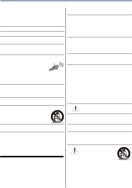
9)Donotdefeatthesafetypurposeofthe polarizedorgroundingtype
plug.Apolarizedplughastwoblades Wide blade
withonewiderthantheother.A groundingtypeplughastwoblades andathirdgroundingprong.Thewide
bladeorthethirdprongareprovidedforyoursafety.If theprovidedplugdoesnotfitintoyouroutlet,consult anelectricianforreplacementoftheobsoleteoutlet.
10)Protectthepowercordfrombeingwalkedonor pinched,particularlyatplugs,convenience receptacles,andthepointwheretheyexitfromthe apparatus.
11)Onlyuseattachments/accessoriesspecifiedby themanufacturer.
12)Useonlywiththecart,stand,tripod,bracket,or tablespecifiedbythemanufacturer,or
soldwiththeapparatus.Whenacartis used,usecautionwhenmovingthecart/ apparatuscombinationtoavoidinjury fromtip-over.
13)Unplugthisapparatusduringlightningstormsor whenunusedforlongperiodsoftime.
14)Referallservicingtoqualifiedservicepersonnel.
Servicingisrequiredwhentheapparatushasbeen damagedinanyway,suchaspower-supplycordor plugisdamaged,liquidhasbeenspilledorobjects havefallenintotheapparatus,theapparatushasbeen exposedtorainormoisture,doesnotoperatenormally, orhasbeendropped.
Additional Safety Precautions
14a)CAUTION: If the TV is dropped and the cabinet or enclosure surface has been damaged or the TV does not operate normally, take the following precautions:
•ALWAYSturnofftheTVandunplugthepowercord toavoidpossibleelectricshockorfire.
•NEVERallowyourbodytocomeincontactwithany brokenglassorliquidfromthedamagedtelevision. TheLCDpanelinsidetheTVcontainsglassanda toxicliquid.Iftheliquidcomesincontactwithyour mouthoreyes,oryourskiniscutbybrokenglass, rinsetheaffectedareathoroughlywithwaterand contactyourdoctorimmediately.
•ALWAYScontactaservicetechniciantoinspectthe TVanytimeithasbeendamagedordropped.
15)CAUTION:
•Toreducetheriskofelectricshock,donotusethe polarizedplugwithanextensioncord,receptacle,or otheroutletunlessthebladescanbeinserted completelytopreventbladeexposure.
•Topreventelectricshock,matchwidebladeofplug towideslot;fullyinsert.
16)CAUTION:
•Donotletchildrenswallowanysmallpartsincluded onorwiththeproductorplaywiththeplasticbag. Keepthesmallpartsandtheplasticbagoutofthe reachofchildren.
17)CAUTION:
•Donotletwaterorotherliquidscomeintocontact withtheproduct,asitmayresultindamage.
18)WARNING:
•Topreventthespreadoffire,keepcandlesorother openflamesawayfromthisproductatalltimes.
•Keeptheproductawayfromdirectsunlight,fireora heatsourcesuchasaheater.Thismayreducethe productlifetimeorresultinfire.
Installation, Care, and Service
Installation
Follow these recommendations and precautions and heed all warnings when installing your TV:
19)WARNING: Never expose the batteries to excessive heat such as sunshine, fire, or the like.
20)ALWAYSplugtheproductintoanoutletthatislocated insuchamannerthatitcanbeeasilyunpluggedin casetheproductrequiresservice.
21)NEVERroutetheproduct’spowercordinsideawallor similarenclosedarea.
22)Nevermodifythisequipment.Changesor modificationsmayvoid:a)thewarranty,andb)the user’sauthoritytooperatethisequipmentunderthe rulesoftheFederalCommunicationsCommission.
23)DANGER: RISK OF
SERIOUS PERSONAL INJURY, DEATH, OR EQUIPMENT DAMAGE!
NeverplacetheTVonanunstable cart,stand,ortable.TheTVmay fall,causingseriouspersonalinjury, death,orseriousdamagetotheTV.
5
24)WhenselectingalocationfortheTV,
•NEVERallowanypartoftheTVtohangoverthe edgeofthesupportingfurniture,
•NEVERplacetheTVontallfurniture(forexample, entertainmentcentersorbookcases)without anchoringboththefurnitureandtheTVtoasuitable support,
•NeverplaceclothorothermaterialbetweentheTV andthesupportingfurniture.
•NEVERallowchildrentoclimbontheTV
25)Toavoiddamagetothisproduct,neverplaceorstore theTVindirectsunlight;hot,humidareas;orareas subjecttoexcessivedustorvibration.
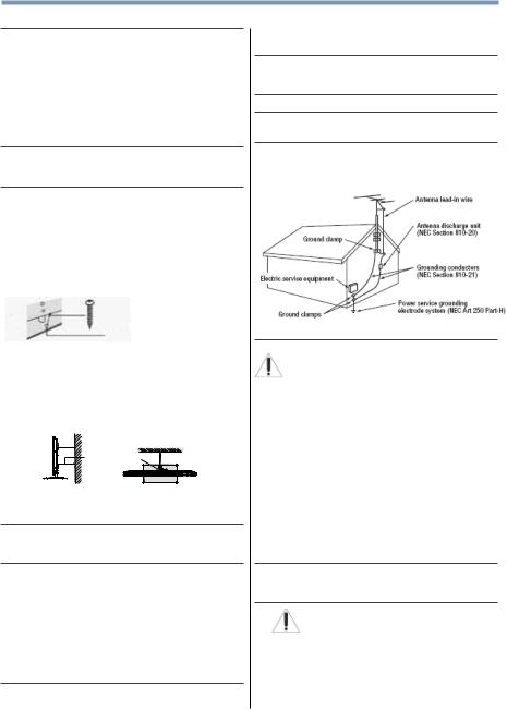
26)AlwaysplacetheTVonthefloororasturdy,level, stablesurfacethatcansupporttheweightoftheunit. SecuretheTVusingoneofthefollowingmethods:
(1)SecuretheTVwithamountingscrew (Recommended.)
•PlacetheTVonasturdysurfacethathasasufficient thicknessandscrewtheunitonthesurfacesecurely byusingthemountingscrewandthefall-prevention screwhole.
Mounting screw
TV Back
Screw hole
(2)SecuretheTVwithasturdystraptoawallstud, pillar,orotherimmovablestructure.When connectingthestrap:
-attachthestraptotheTVusingthehooksontheback oftheTV,theclipsonthepedestal,ortheholeinthe baseofthepedestalasavailable.
-makesurethestrapistight,secure,andparalleltothe
floor. |
Sturdy strap (as short as possible) |
|
|
||
|
7" min. |
Hook |
|
TV side |
TV top |
NOTE: The 23L1350U and 23L2300U do not include a hook on the back of the TV.
27)Theproductshallnotbeexposedtodrippingor splashing,andthatnoobjectsfilledwithliquids,such asvases,shallbeplacedontheapparatus.
28)NeverblockorcovertheslotsoropeningsintheTV cabinetback,bottom,andsides.NeverplacetheTV:
•onabed,sofa,rug,orsimilarsurface;
•tooclosetodrapes,curtains,orwalls;or
•inaconfinedspacesuchasabookcase,built-in cabinet,oranyotherplacewithpoorventilation.
Theslotsandopeningsareprovidedtoprotectthe TVfromoverheatingandtohelpmaintainreliable operationoftheTV.Leaveaspaceofatleast4 (four)inchesaroundtheTV.
29)Alwaysleaveaspaceofatleast4(four)inchesaround theTV.Theslotsandopeningsareprovidedtoprotect
theTVfromoverheatingandtohelpmaintainreliable operationoftheTV.
30)Neverallowanythingtorestonorrolloverthepower cord,andneverplacetheTVwherethepowercordis subjecttowearorabuse.
31)Neveroverloadwalloutletsandextensioncords.
32)Alwaysoperatethisequipmentfroma120VAC,60Hz powersource.
33)Alwaysmakesuretheantennasystemisproperly groundedtoprovideadequateprotectionagainst voltagesurgesandbuilt-upstaticcharges(seeSection 810oftheNationalElectricCode).
34)
DANGER: RISK OF SERIOUS
PERSONAL INJURY OR DEATH!
•Wheninstallingarooftopantenna,useextremecare tomakesureyouareneverinapositionwhereyour body(oranyitemyouareincontactwith,suchasa ladderorscrewdriver)canaccidentallytouch overheadpowerlines.Neverlocatetheantenna nearoverheadpowerlinesorotherelectrical circuits.
•Neverattempttoinstallanyofthefollowingduring lightningactivity:a)anantennasystem;orb)cables, wires,oranyhometheatercomponentconnectedto anantennaorphonesystem.
Care
For better performance and safer operation of your TOSHIBATV, follow these recommendations and precautions:
35)IfyouusetheTVinaroomwhosetemperatureis32°F (0°C)orbelow,thepicturebrightnessmayvaryuntil theLEDwarmsup.Thisisnotasignofmalfunction.
36)WARNING: RISK OF SERIOUS PERSONAL INJURY OR EQUIPMENT DAMAGE!
•Neverusechemicals(suchasairfresheners, cleaningagents,etc.)onorneartheTVpedestal. Studiesindicatethatplasticsmayweakenandcrack overtimefromthecombinedeffectsofchemical agentsandmechanicalstress(suchastheweightof theTV).Failuretofollowtheseinstructionscould
6
resultinseriousinjuryand/orpermanentdamageto TVandTVpedestal.
•AlwaysunplugtheTVbeforecleaning.Gentlywipe thedisplaypanelsurface(theTVscreen)usinga dry,softcloth(cotton,flannel,etc.).Ahardclothmay damagethesurfaceofthepanel.Avoidcontactwith alcohol,thinner,benzene,acidicoralkalinesolvent cleaners,abrasivecleaners,orchemicalcloths, whichmaydamagethesurface.Neversprayvolatile compoundssuchasinsecticideonthecabinet. Suchproductsmaydamageordiscolorthecabinet.
37)Neverhit,press,orplaceanythingonthebackcover. Theseactionswilldamageinternalparts.
38)
WARNING:
RISKOFELECTRICSHOCK!
Neverspillliquidsorpushobjectsofanykindinto theTVcabinetslots.
39)Duringalighteningstorm,donottouchtheconnecting cablesorproduct.
40)ForaddedprotectionofyourTVfromlightningand powersurges,alwaysunplugthepowercordand disconnecttheantennafromtheTVifyouleavetheTV unattendedorunusedforlongperiodsoftime.
41)AlwaysunplugtheTVtocompletelydisconnectfrom mainspower.WhentheTVisturnedoffusingtheon/ offswitch,itisnotcompletelydisconnectedfrompower andaminuteamountofcurrentisstillconsumed.
42)Duringnormaluse,theTVmaymakeoccasional snappingorpoppingsounds.Thisisnormal,especially whentheunitisbeingturnedonoroff.Ifthesesounds becomefrequentorcontinuous,unplugthepowercord andcontactaToshibaAuthorizedServiceProvider.
43)WARNING: RISK OF SERIOUS PERSONAL INJURY OR EQUIPMENT DAMAGE!
Neverstrikethescreenwithasharporheavy object.
44)
•TheLCDscreenofthisproductcanbedamagedby ultravioletradiationfromthesun.Whenselectinga locationforthetelevision,avoidlocationswherethe screenmaybeexposedtodirectsunlight,suchasin frontofawindow.
•Nevertouch,press,orplaceanythingontheLCD screen.TheseactionswilldamagetheLCDscreen. IfyouneedtocleantheLCDscreen,followthe instructionsinitem36)onpage5.
Service
45)
WARNING:
RISKOFELECTRICSHOCK!
NeverattempttoservicetheTVyourself.Opening andremovingthecoversmayexposeyouto dangerousvoltageorotherhazards.Failureto followthisWARNINGmayresultindeathor seriousinjury.Referallservicingnotspecifiedin thismanualtoaToshibaAuthorizedService Provider.
46)IfyouhavetheTVserviced:
•Asktheservicetechniciantouseonlyreplacement partsspecifiedbythemanufacturer.
•Uponcompletionofservice,asktheservice techniciantoperformroutinesafetychecksto determinethattheTVisinsafeoperatingcondition.
Choosing a location for your LED TV
To Display your LED TV on the included Pedestal Stand:
Observe the following safety precautions:
1)Read and follow the pedestal assembly instructions included with the pedestal.
CAUTION: Before beginning pedestal assembly, carefully lay the front of the LCD Panel face down on a flat, cushioned surface such as a quilt or blanket. Leave the bottom of the unit protruding over the edge of the surface and assemble the pedestal as indicated below.
Note: Extreme care should always be used when attaching the pedestal stand to avoid damage to
the LCD panel.
2)PlacetheTVonasturdy,levelsurfacethatcan supporttheweightoftheTV.
3)BesuretosecuretheTVtoawall,pillar,surface,or otherimmovablestructureseeitem26)onpage5 for additionaldetails.
To Display your LED TV using a Wall Bracket:
If you decide to wall mount your LED TV, always use a wall bracket Listed by an independent laboratory (such as UL, CSA, ETL) that is appropriate for the size
and weight of the TV:
1)CAUTION: Two people are required for installation.
2)Unplugandremoveanycablesand/orother componentconnectorsfromtherearoftheTV
3)RemovethescrewsoftheVESAMountingPattern showinthetablebelow,ifapplicable.
CAUTION:Donotusethescrewsremovedfrom thebackcovertoattachthewallmountbracketto theTV.
4)Alwaysusethescrewssuppliedorrecommendedby thewallmountmanufacturer.
5)Followtheinstructionsprovidedwithyourwallbracket. Beforeproceeding,makesuretheappropriate bracket(s)areattachedtothewallandthebackofthe TVasdescribedintheinstructionsprovidedwiththe wallbracket.
6)Afterattachingtheappropriatebracket(s)tothewall andthebackoftheTV,removethepedestalstand fromtheTV,asdescribedbelow.
7)VESAMountingPattern
TV Size |
Hole Pattern (HxV) |
Screw Size |
|
|
|
23” |
100mm x 100mm |
M4 |
29” |
200mm x 100mm |
M6 |
32” |
200mm x 200mm |
M6 |
39” |
200mm x 200mm |
M6 |
50” |
400mm x 400mm |
M8 |
58” |
400mm x 400mm |
M8 |

7
Removing the Pedestal Stand
1)Carefully lay the front of the unit face down on a flat, cushioned surface such as a quilt or blanket. Leave the stand protruding over the edge of the surface.
Note: Extreme care should always be used when removing the pedestal stand to avoid damage to the LCD panel.
2)Removethestandscrewsshowninthediagram below.Thiswillallowremovalofthepedestalstand.
3)Onceyouhaveremovedthescrewsholdingthe pedestalstandinplace,removethepedestalstand fromtheTV.
23” TV.
VESA Mounting Pattern
Two stand screws
29” TV.
VESA Mounting Pattern
|
|
|
|
|
|
|
|
Two stand screws |
Hook Sturdy strap |
||||||
(as short as possible) |
|||||||
32” TV. VESA Mounting Pattern |
|||||||
|
|
||||||
39” TV.
VESA Mounting Pattern
Two stand screws |
|
Hook Sturdy strap |
|
||
|
(as short as possible) |
|
|
|
50” TV.
VESA Mounting Pattern
Four stand screws |
|
Hook Sturdy strap |
|
||
|
(as short as possible) |
|
|
|
58” TV. |
VESA Mounting Pattern |
|
Four stand screws |
Hook Sturdy strap |
|
(as short as possible) |
||
|
CAUTION: Always place the TV on the floor or a sturdy, level, stable surface that can support the weight of the unit. To secure the TV, use a sturdy strap from the hook(s) on the rear of the TV to a wall stud, pillar, or other immovable structure. Make sure the strap is tight, secure, and parallel to the floor.
NOTE: The 23L1350U and 23L2300U do not include a hook on the back of the TV.
Two stand screws |
Hook Sturdy strap |
|
(as short as possible) |
||
|
8
FCC Declaration of Conformity Compliance Statement (Part 15):
Toshiba 23L1350U, 29L1350U, 32L1350U, 39L1350U, 50L1350U, 58L1350U, 23L2300U, 32L2300U, 39L2300U, 50L2300U Television models comply with Part 15 of the FCC Rules.
Operation issubjecttothefollowingtwo conditions:
(1)Thisdevicemaynotcause harmful interference,and
(2)Thisdevicemustacceptanyinterferencereceived, includinginterferencethatmay causeundesiredoperation.
Thepartyresponsibleforcompliance to theserulesis: ToshibaAmericaInformationSystems,Inc.
9740Irvine Blvd.,Irvine,CA92618. Ph:800-631-3811
Note: This equipment has been tested and found to comply with the limits for a Class B digital device, pursuant to Part 15 of the FCC Rules. These limits are designed to provide reasonable protection against harmful interference in a residential installation. This equipment generates, uses, and can radiate radio frequency energy and, if not installed and used in accordance with the instructions, may cause harmful interference to radio communications. However, there is no guarantee that interference will not occur in a particular installation. If this equipment does cause harmful interference to radio or television reception, which can be determined by removing and applying power to the equipment, the user is encouraged to try to correct the interference by one of the following measures:
•Reorient or relocate the receiving antenna.
•Increase the separation between the equipment and receiver.
•Connect the equipment into an outlet on a circuit different from that to which the receiver is connected.
•Consult the dealer or an experienced radio/TVtechnician for help.
Caution: Changes or modifications to this equipment not expressly approved by Toshiba could void the user’s authority to operate this equipment.
ENERGY STAR® User Information
ENERGYSTAR User Information Statement: the factory default settings of this television meet ENERGYSTAR® requirements. Changing Picture Settings may increase energy consumption, possibly beyond the limits required for ENERGYSTAR qualification.
To ensure your television is operating at optimal energy efficiency, select [Home] mode during initial activation.To return to [Home] mode settings, select [Standard] picture mode. [Standard] mode is recommended for normal home use.
ENERGYSTAR® qualifiedTV. Products that earn the ENERGYSTAR prevent green house gas emissions by meeting strict guidelines set by the U.S. Environmental ProtectionAgency. ENERGYSTAR and the ENERGYSTAR mark are registered U.S. marks.
Important notes about your TV
The following symptoms are technical limitations of LCD Display technology and are not an indication of malfunction; therefore,Toshiba is not responsible for perceived issues resulting from these symptoms.
1)Anafterimage(ghost)mayappearonthescreenifa fixed,non-movingimageappearsforalongperiodof time.Theafterimageisnotpermanentandwill disappearinashortperiodoftime.
2)TheLCDpanelcontainedinthisTVismanufactured usinganextremelyhighlevelofprecisiontechnology; however,theremaybeanoccasionalpixel(dotof light)thatdoesnotoperateproperly(doesnotlight, remainsconstantlylit,etc.).Thisisastructural propertyofLCDtechnology,isnotasignof malfunction,andisnotcoveredunderyourwarranty. Suchpixelsarenotvisiblewhenthepictureisviewed fromanormalviewingdistance.
Note: Interactive video games that involve shooting a “gun” type of joystick at an on-screen target may not work with this TV.

9
Trademark Information
•ColorStream,DynaLight,ClearScan,GameTimer, NativeMode,CinemaMode,ColorMaster,SurfLock aretrademarksorregisteredtrademarksofToshiba AmericaInformationSystems,Inc.
•Blu-rayDisc™,Blu-ray™,andthelogosare trademarksoftheBlu-rayDiscAssociation.
•AudysseyEQ® providesclear,accurate, andnaturalsoundrightoutofthebox.This technologyensuresyouenjoyyouraudio experienceasmuchasyourvideo.
•AudysseyABX™technologyuses sophisticateddriveranalysisandlow frequencymonitoringtoextendtherange andbassofsmallspeakers.Thisenables thesystemtoproducelowerfrequencies thanwouldbepossiblewithatraditional systemofthesamesize.
• Manufacturedunderlicensefrom AudysseyLaboratories.U.S.andforeign patentspending.
AudysseyEQ® isaregisteredtrademark, AudysseyABX™isatrademarkof AudysseyLaboratories.
• ManufacturedunderlicensefromDolby® Laboratories.Dolby® andthedouble-D symbolaretrademarksofDolby® Laboratories.
•ThetermsHDMIandHDMIHigh-Definition MultimediaInterface,andtheHDMILogo aretrademarksorregisteredtrademarksof HDMILicensingLLCintheUnitedStates andothercountries.
•MPEGLayer-3audiocodingtechnology licensedfromFraunhoferIISandThomson.
•ThisproductioncontainsBitstreamVera Sansfontsunderthefollowingcopyright: Copyright©2003byBitstream,Inc.All RightsReserved.BitstreamVeraisa trademarkofBitstream,Inc.
•Allotherbrandandproductnamesare trademarksorregisteredtrademarksof theirrespectivecompanies.
Copyright
This guide is copyrighted byToshibaAmerica Information Systems, Inc. with all rights reserved. Under the copyright laws, this guide cannot be reproduced in any form without the prior written permission ofToshiba. No patent liability is assumed, however, with respect to the use of the information contained herein.
©2013 byToshibaAmerica Information Systems, Inc.All rights reserved.
Notice
The information contained in this manual, including but not limited to any product specifications, is subject to change without notice.
TOSHIBACORPORATIONANDTOSHIBA AMERICAINFORMATION SYSTEMS, INC. (TOSHIBA) PROVIDES NOWARRANTYWITH REGARDTOTHIS MANUALORANYOTHER INFORMATION CONTAINED HEREINAND HEREBYEXPRESSLYDISCLAIMSANYIMPLIED WARRANTIES OFMERCHANTABILITYOR FITNESS FORANYPARTICULAR PURPOSEWITH REGARDTOANYOFTHE FOREGOING.TOSHIBA ASSUMES NO LIABILITYFORANYDAMAGES INCURRED DIRECTLYOR INDIRECTLYFROM ANYTECHNICALORTYPOGRAPHICALERRORS OR OMISSIONS CONTAINED HEREIN OR FOR DISCREPANCIES BETWEENTHE PRODUCTAND THE MANUAL. IN NO EVENTSHALLTOSHIBABE LIABLE FORANYINCIDENTAL, CONSEQUENTIAL, SPECIAL, OR EXEMPLARY DAMAGES,WHETHER BASED ONTORT, CONTRACTOR OTHERWISE,ARISING OUTOF OR IN CONNECTIONWITHTHIS MANUALOR ANYOTHER INFORMATION CONTAINED HEREIN ORTHE USETHEREOF.

Contents |
|
|
Chapter 1: Introduction.............................................................. |
16 |
|
Features................................................................... |
|
17 |
Overview |
of installation, setup, and use................... |
18 |
TV front and side panel controls and connections.... |
19 |
|
TV back panel connections....................................... |
21 |
|
Chapter 2: Connecting Your TV................................................. |
23 |
|
Overview of cable types........................................... |
23 |
|
Coaxial (F-type) cable ........................................ |
23 |
|
Standard A/V cables (red/white/yellow).............. |
24 |
|
Component video cables (red/green/blue).......... |
24 |
|
HDMITM cable (with HDMI Logo)........................ |
24 |
|
Optical audio cable............................................. |
25 |
|
Analog RGB (15-pin) computer cable................. |
25 |
|
3.5mm Stereo to RCA Y-cable............................ |
25 |
|
About the connection illustrations...................... |
25 |
|
Connecting a VCR, antenna, cable TV, |
|
|
or camcorder..................................................... |
26 |
|
10
|
11 |
Contents |
|
Connecting a Blu-ray™ / DVD player, satellite |
|
receiver with ColorStream® or VCR ................... |
27 |
Connecting an HDMITM or DVI device to |
|
the HDMITM input................................................ |
30 |
HDMITM CEC connection........................................... |
33 |
Connecting a digital audio system............................ |
34 |
Connecting an analog audio system......................... |
36 |
Connecting a computer............................................ |
37 |
Connecting a computer to the TV’s PC IN |
|
terminal....................................................... |
37 |
Connection to the TV’s HDMITM terminal............. |
39 |
Chapter 3: Using the Remote Control....................................... |
42 |
Installing batteries................................................... |
42 |
Remote control effective range................................ |
43 |
Learning about the remote control........................... |
44 |
Chapter 4: Menu Layout and Navigation................................... |
47 |
Main menu layout.................................................... |
47 |
Navigating the menu system.................................... |
49 |
Chapter 5: Setting up your TV.................................................... |
50 |
Initial Setup.............................................................. |
50 |
Installation setup selection....................................... |
51 |
Storing channels in memory (optional).................... |
52 |
Auto Tuning............................................................. |
52 |
Manual Tuning......................................................... |
54 |
Setting channel skip................................................. |
54 |
Setting the AV input mode........................................ |
55 |
Setting the HDMITM audio mode............................... |
56 |
Setting the time zone................................................ |
57 |
Viewing the system status........................................ |
57 |
Resetting Factory Defaults................................. |
57 |
Chapter 6: Setting up your TV.................................................... |
58 |
Selecting the video input source............................... |
58 |
12 |
Contents |
|
|
|
|
|
|
|
|
|
|
|
Labeling the video input sources.............................. |
60 |
|
|
Tuning channels using the Channel Browser............ |
61 |
|
|
Favorites browser.................................................... |
62 |
|
|
Elements of the Channel Browser....................... |
63 |
|
|
Adding and clearing channels and inputs |
|
|
|
in the History List......................................... |
65 |
|
|
Tuning to the next programmed channel............ |
65 |
|
|
Tuning to a specific channel |
|
|
|
(programmed or unprogrammed)................ |
65 |
|
|
Switching between two channels using Channel |
|
|
|
Return......................................................... |
66 |
|
|
Switching between two channels using |
|
|
|
SurfLock™................................................... |
66 |
|
|
Selecting the picture size.......................................... |
67 |
|
|
Full..................................................................... |
68 |
|
|
TheaterWide 1.................................................... |
68 |
|
|
TheaterWide 2.................................................... |
68 |
|
|
TheaterWide 3.................................................... |
69 |
|
|
Native................................................................ |
69 |
|
|
4:3..................................................................... |
70 |
|
|
Normal............................................................... |
70 |
|
|
Dot by Dot.......................................................... |
70 |
|
|
Scrolling the TheaterWide® picture |
|
|
|
(TheaterWide 2 and 3 only)................................ |
71 |
|
|
Using the Auto Aspect feature.................................. |
71 |
|
|
Using the 4:3 Stretch............................................... |
72 |
|
|
Using the FREEZE feature......................................... |
72 |
|
|
Adjusting the picture ............................................... |
73 |
|
|
Selecting the picture mode................................. |
73 |
|
|
Adjusting the picture quality............................... |
74 |
|
|
Using closed captions.............................................. |
75 |
|
|
Base closed captions......................................... |
75 |
|
|
Digital CC settings.............................................. |
76 |
|
|
Adjusting the audio.................................................. |
77 |
|
|
Muting the sound............................................... |
77 |
|

|
13 |
Contents |
|
Using the Digital Audio Selection....................... |
78 |
Selecting stereo/SAP broadcasts....................... |
78 |
Adjusting the audio quality................................. |
79 |
Audyssey® technologies.................................... |
80 |
Audyssey ABX™................................................. |
80 |
Stable Sound..................................................... |
80 |
Selecting the optical audio output format........... |
80 |
Using the Dolby® Digital Dynamic Range |
|
Control feature ............................................ |
81 |
Selecting the PIN code............................................. |
81 |
Enter a new PIN code......................................... |
81 |
Forgotten PIN code............................................ |
81 |
Changing or deleting your PIN code................... |
81 |
Using parental controls (for USA region).................. |
82 |
Blocking TV programs and movies by rating |
|
(V-Chip)....................................................... |
82 |
Downloading an additional rating system........... |
83 |
Displaying ratings.............................................. |
85 |
Unlocking programs temporarily....................... |
86 |
Using the input lock feature...................................... |
86 |
Locking channels..................................................... |
87 |
Using the GameTimer®....................................... |
87 |
Using the panel lock feature............................... |
88 |
Using the PC settings feature................................... |
89 |
Setting the PC Audio.......................................... |
90 |
Using the Media Player............................................ |
91 |
Auto Start function............................................. |
92 |
To open the Media Player................................... |
92 |
Playing music files............................................. |
95 |
Viewing photo files and playing music files |
|
at the same time .......................................... |
96 |
Sorting photo or music files............................... |
96 |
Setting the sleep timer............................................. |
97 |
No Signal Power Down............................................ |
98 |
Using HDMITM CEC................................................... |
98 |
14 |
Contents |
|
|
|
|
|
|
|
|
|
|
|
HDMITM CEC playback device |
|
|
|
(DVD player, etc.) control ............................ |
99 |
|
|
Other HDMITM CEC functions............................ |
101 |
|
|
Setting up HDMITM CEC.................................... |
101 |
|
|
Using the HDMITM settings feature.......................... |
101 |
|
|
Using the HDMITM settings feature.......................... |
102 |
|
|
HDMITM 1(2, or 3) RGB Range.......................... |
102 |
|
|
HDMITM Information Display............................ |
102 |
|
|
Displaying TV status information........................... |
102 |
|
|
Understanding the last mode memory feature........ |
103 |
|
Chapter 7: Using the TV’s Advanced Features........................ |
104 |
||
|
Using the advanced picture settings....................... |
104 |
|
|
ColorMaster™.................................................. |
104 |
|
|
Base Color Adjustment..................................... |
104 |
|
|
Color Temperature........................................... |
105 |
|
|
Static Gamma.................................................. |
105 |
|
|
Brightness Sensor (for 39/50L2300U and |
|
|
|
39/50/58L1350U)...................................... |
105 |
|
|
DynaLight®...................................................... |
106 |
|
|
Dynamic Contrast............................................ |
106 |
|
|
Cinema Mode (except for 58L1350U)............... |
106 |
|
|
ClearScan® (for 58L1350U).............................. |
106 |
|
|
Noise Reduction.............................................. |
107 |
|
Chapter 8: Troubleshooting..................................................... |
108 |
||
|
General troubleshooting........................................ |
108 |
|
|
Picture problems................................................... |
109 |
|
|
Sound problems.................................................... |
110 |
|
|
Remote control problems...................................... |
111 |
|
|
Channel tuning problems....................................... |
111 |
|
|
Closed caption problems....................................... |
112 |
|
|
Rating blocking (V-Chip) problems........................ |
112 |
|
|
No HDMITM CEC operation...................................... |
112 |
|
|
HDMITM problems.................................................. |
113 |
|
|
Media Player problems.......................................... |
113 |
|

Contents 15
If the problem persists after trying the solutions....113
Appendix A: Specifications...................................................... |
114 |
Television system................................................... |
114 |
Channel coverage.................................................. |
114 |
Power source......................................................... |
115 |
Power maximum current................................. |
115 |
Power consumption......................................... |
115 |
Audio power.................................................... |
115 |
Speaker type.......................................................... |
116 |
Video/audio terminals............................................ |
116 |
Video/audio input............................................. |
116 |
ColorStream® (component video) HD input...... |
116 |
HDMITM input................................................... |
116 |
Digital audio output.......................................... |
117 |
PC input........................................................... |
117 |
Dimensions............................................................ |
117 |
Weight (Mass)................................................. |
117 |
Operating conditions........................................ |
118 |
Supplied accessories............................................. |
118 |
Acceptable signal formats for PC IN, HDMITM......... |
118 |
PC IN signal formats........................................ |
118 |
HDMITM signal formats..................................... |
119 |
Appendix B: License Agreement............................................. |
120 |
Chapter 1
Introduction
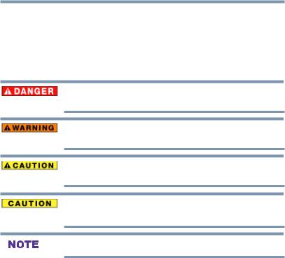
Safety icons
Thismanualcontainssafetyinstructionsthatmustbeobservedtoavoidpotential hazardsthatcouldresultinpersonalinjuries,damagetoyourequipment,orloss ofdata.Thesesafetycautionshavebeenclassifiedaccordingtotheseriousnessof therisk,andiconshighlighttheseinstructionsasfollows:
Indicates an imminently hazardous situation which, if not avoided, will result in death or serious injury.
Indicates a potentially hazardous situation which, if not avoided, could result in death or serious injury.
Indicates a potentially hazardous situation which, if not avoided, may result in minor or moderate injury.
Indicates a potentially hazardous situation which, if not avoided, may result in property damage.
Provides important information.
16

IntroductionFeatures 17
Features
The following are just a few of the many exciting features of your newToshiba wide screen, integrated HD, LEDTV:
vIntegrateddigitaltuning(8VSBATSCandQAM)—
Eliminates the need for a separate digital converter set-top box (in most cases).
v1366 x 768 output resolution (29L1350U, 32L1350U, 32L2300U)
v1920 x 1080 output resolution (23L1350U, 39L1350U, 50L1350U, 58L1350U, 23L2300U, 39L2300U, and 50L2300U)
vThree HDMITM —Digital, High-Definition Multimedia Interfaces with 1080p input support. See “Connecting an HDMITM or DVI device to the HDMITM input” on page 30
vColorStream® HD—High-resolution component video input and shared composite video input, see “Connectinga Blu-ray™ / DVD player, satellite receiver with ColorStream® orVCR” on page 27
vDigitalAudio Out—Optical audio connection with Dolby® Digital optical output form. See “Connecting a digital audio system” on page 34
vAudyssey EQ® andABXTM—Audio technologies for clear, well-balancedsound,see“Audyssey®technologies”onpage80
vColorMasterTM—Allows you to adjust theTV’s standard colors, see “ColorMaster™” on page 104
vCinema Mode—Shows film-like quality movies, see “Cinema Mode (except for 58L1350U)” on page 106
vDNR—Dynamic Noise Reduction technology that filters out video noise without decreasing the picture sharpness for clean, crystal-clear images, see “DNR” on page 107
vClearScan®240Hz(for58L1350U)
—Uses both frame interpolation technology and advanced backlight control with image synchronization to quadruple the TVrefresh rate for an even clearer fast motion video, see “ClearScan® (for 58L1350U)” on page 106
vClearScan®120Hz(for32/39/50L1350Uand 32/39/50L2300U)
— Doubles the refresh rate for clearer fast motion video.
vPC IN (Analog RGB)—Computer terminal, see “Connecting a computer to theTV’s PC IN terminal” on page 37

18 Introduction
Overviewofinstallation,setup,anduse
v HDMITM CEC—Allows control of external devices from the
TVremote via HDMITM connection, see “UsingHDMITM
CEC” on page 98
v Media Player—Allows you to view photo files and play music
files, see “Using the Media Player” on page 91
v ENERGYSTAR® qualified.
Overview of installation, setup, and use
Follow these steps to set up yourTVand begin using its many exciting features.
1Carefully read the important safety, installation, care, and service information. Keep this document for future reference.
2To choose a location for theTV:
v Read “Important notes about yourTV” on page 8
vPlace theTVon the floor or a sturdy, level, stable surface that can support the weight of the unit. Secure theTVto a wall, pillar, or other immovable structure, see 26)
on page 5.
vPlace theTVin a location where light does not reflect on the screen.
vAlways leave a space of at least 4 (four) inches around the TV.The slots and openings are provided to protect theTV from overheating and to help maintain reliable operation of theTV.
3Do not plug in any power cords until after you have connected all cables and devices to yourTV.
4Before connecting cables or devices to theTV, learn the functions of theTV’s connections and controls, see “Overview of cable types” on page 23
5Connect your other electronic device(s) to theTV, see “Connecting an HDMITM or DVI device to the HDMITM input” on page 30
6Install the batteries in the remote control, see “Installing batteries” on page 42
7See “Learning about the remote control” on page 44 for an overview of the buttons on the remote control.
8After connecting all cables and devices, plug in the power cords for yourTVand other devices.Then press the POWER button on theTVcontrol panel or remote control to turn on the TV. If theTVstops responding to the buttons on the remote control orTVcontrol panel and you cannot turn theTVoff or on, unplug the power cords for a few seconds and then plug them in and try again.
9See “Navigating the menu system” on page 49 for a quick overview of navigating theTV’s menu system.
Introduction 19
TVfrontandsidepanelcontrolsandconnections
10Program channels into theTV’s channel memory, see “AutoTuning” on page 52
11For details on using theTV’s features, see Chapter 6 and Chapter 7
12For help, refer to “Troubleshooting” on page 108
13Fortechnicalspecifications,see“Specifications”onpage114
14For the End User LicenseAgreement, see “License Agreement” on page 120
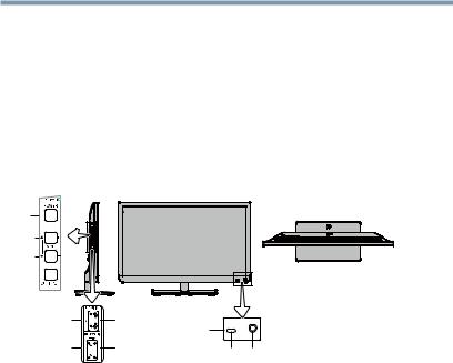
TV front and side panel controls and connections
Left side panel |
TV front |
3 |
TV top |
|
4 
5 

6 |
HDMITM port |
|
|
|
|
8 |
|
7 |
USB port |
2 |
1 |
|
|
(Sample Illustration) L1350U/L2300U Series (except 58L1350U)
—Front and side panel controls and connections
1 PowerOn/Standby LED—Power indicator light, (glows green when theTVpower is On).
2Remote sensor(embedded)—Point the remote control toward this remote sensor.
3POWER—Turns theTVOn/Off. If theTVstops responding to the buttons on the remote control orTVcontrol panel and you cannot turn off theTV, press and hold the POWER button on theTVcontrol panel for a few seconds to reset theTV.
4ARROWS  /
/ /+/ ─ — Adjust the volume level, change the channel, or change the input or source you are viewing, depending on the mode, which is selected by the CH/INPUT button.
5CH/INPUT—Switches the function of the ARROWS  /
/ /+/ ─ buttons to select the volume, channel, or input mode.
•InVolume mode, the arrow buttons increase or decrease the volume.
•In Channel mode, the arrow buttons change the channel up or down.
•In Source mode, the arrow buttons toggle the input from one source to the next.
6HDMITM IN—High-Definition Multimedia Interface input.
20 Introduction
TVfrontandsidepanelcontrolsandconnections
7USB port—Accesses JPEG or MP3 files, or updatesTVfirmware.
8Brightness Sensor( for39/50/58L1350U and 39/50L2300U)—
Detects the ambient light conditions to optimize the backlighting levels.
|
Left side panel |
3 |
TV front |
4 |
TV top |
5 |
6
7
8
9
2 1
(Sample Illustration) 58L1350U — Front and side panel controls and connections
1PowerOn/Standby LED—Power indicator light, (glows green when theTVpower is On).
2Remote sensor(embedded)—Point the remote control toward this remote sensor.
3POWER—Turns theTVOn/Off. If theTVstops responding to the buttons on the remote control orTVcontrol panel and you cannot turn off theTV, press and hold the POWER button on theTV control panel for a few seconds to reset theTV.
4ARROWS  /
/ /+/ ─ — Adjust the volume level, change the channel, or change the input or source you are viewing, depending on the mode, which is selected by the CH/INPUT button.
5CH/INPUT—Switches the function of the VOL+/─ buttons to select the volume, channel, or input mode.
•InVolume mode, the arrow buttons increase or decrease the volume.
•In Channel mode, the arrow buttons change the channel up or down.
•In Source mode, the arrow buttons toggle the input from one source to the next.
6HDMITM IN—High-Definition Multimedia Interface input.
7DigitalAUDIO OUT—Optical audio output in Dolby® Digital or PCM (pulse-code modulation) format for connecting an external Dolby® Digital decoder, amplifier, or home theater system with optical audio input.
Introduction 21
TVbackpanelconnections
8USB port—Accesses JPEG or MP3 files, or updatesTVfirmware.
9Brightness Sensor—Detects the ambient light conditions to optimize the backlighting levels.
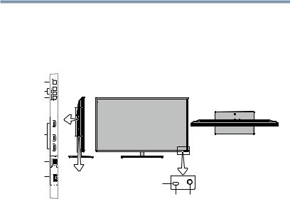
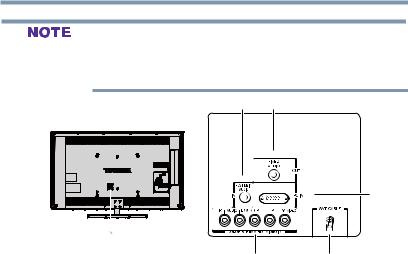
TV back panel connections
For explanations of cable types and connections, see on page 23.
6 5
7
4
Power Cord
1 |
2 |
3 |
(Sample Illustration) L1350U/L2300U Series (except 58L1350U)
— Back panel connections
1HDMITM IN—High-Definition Multimedia Interface input receives digital audio and uncompressed digital video from an HDMITM device or uncompressed digital video from a DVI device. HDMITM connection is necessary to receive 1080p signals.
2ColorStream® HD—High-resolution component video input and shared composite video input, see “Connectinga Blu-ray™ / DVD player, satellite receiver with ColorStream® orVCR” on page 27
3ANT/CABLE—Antenna input that supports analog (NTSC) and digital (ATSC) off-air antenna signals and analog and digital cableTV(QAM) signals.
4ANALOGAUDIO OUT—Analog audio outputs for connecting an audio amplifier.
5PC IN—Connects a personal computer.
6PC/HDMI-1 (Audio) IN—PC audio input terminal is shared with an HDMI-1 analog audio input terminal, and its use can be configured in theAudio Setup menu, see “Setting the PC Audio” on page 90
7DigitalAUDIO OUT—Optical audio output in Dolby® Digital or PCM (pulse-code modulation) format for connecting an external Dolby® Digital decoder, amplifier, or home theater system with optical audio input.
22 Introduction
TVbackpanelconnections
Component/Standard (composite) video cables carry only video information; separate audio cables are required for a complete connection.(Sample Illustration) L1350U/L2300U Series - Back panel connections
5 4
3
Power Cord
1 |
|
2 |
(Sample Illustration) 58L1350U — Back panel connections
1ColorStream® HD—High-resolution component video input and shared composite video input, see “Connectinga Blu-ray™ / DVD player, satellite receiver with ColorStream® orVCR” on page 27
2ANT/CABLE—Antenna input that supports analog (NTSC) and digital (ATSC) off-air antenna signals and analog and digital cableTV(QAM) signals.
3PC IN—Connects a personal computer.
4FIXEDAUDIO OUT—Analog audio outputs for connecting an audio amplifier.
5PC/HDMI-1 (Audio) IN—PC audio input terminal is shared with an HDMI-1 analog audio input terminal, and its use can be configured in theAudio Setup menu, see “Setting the PC Audio” on page 90
Chapter 2
Connecting Your TV
Overview of cable types
Before purchasing cables, know the connector types your devices require.You can purchase cables from most stores that sell audio/ video devices.
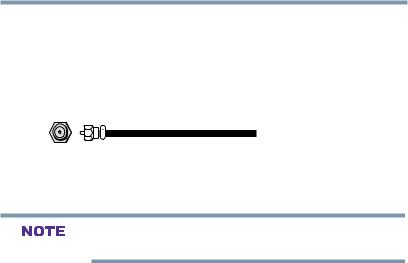
Coaxial (F-type) cable
(Sample Illustration) Coaxial cable
Coaxial (F-type) cable connects your antenna, cableTVservice, and/or cable converter box to theANT/CABLE input on yourTV.
Please tighten this connection by hand. Using tools may damage the connection.
23
24 Connecting Your TV
Overviewofcabletypes
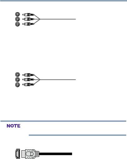
Standard A/V cables (red/white/yellow)
(Sample Illustration) StandardAVcables
StandardA/Vcables (composite video) usually come in sets of three, and connect to video devices with analog audio and composite video output.These cables (and the related inputs on yourTV) are typically color-coded according to use: yellow for video, red for stereo right audio, and white for stereo left (or mono) audio.
Component video cables (red/green/blue)
Component video cables (red/green/blue)
Component video cables come in sets of three and connect with video devices with component video output. (ColorStream® is Toshiba’s brand of component video.)These cables are typically color-coded red, green, and blue. Separate audio cables are required for a complete connection.
Component video cables provide better picture quality than composite video cables.
HDMITM cable (with HDMI Logo)
(Sample Illustration) HDMITM cable
HDMITM (High-Definition Multimedia Interface) cable connects to devices that have an HDMITM output.An HDMITM cable delivers digital audio and video in its native format. Separate audio cables are not required, see “Connecting anHDMITM or DVI device to theHDMITM input” on page 30
Connecting Your TV 25
Overviewofcabletypes
HDMITM cables provide the best audio and picture quality.
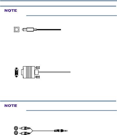
Optical audio cable
(Sample Illustration) Optical audio cable
Optical audio cable connect receivers with Dolby® Digital or PCM (pulse-code modulation) optical audio input to theTV’s Digital Audio Out terminal, see “Connecting a digital audio system” on
page 34
Analog RGB (15-pin) computer cable
(Sample Illustration)Analog RGB (15-pin) computer cable
Analog RGB (15-pin) computer cable connects a computer to the to theTV’s PC IN terminal, see “Connecting a computer” on page 37
Separate audio cables are required.
3.5mm Stereo to RCA Y-cable
(Sample Illustration) 3.5mm Stereo to RCAY-cable
3.5mm Stereo to RCAY-cable connects an audio signal from DVI device toTV.
About the connection illustrations
You can connect different types and brands of devices to yourTVin several different configurations.The connection illustrations in this manual are representative of typical device connections only.The input/output terminals on your devices may differ from those illustrated herein. For details on connecting and using your specific
devices, refer to each device’s User’s Guide.
26 |
Connecting Your TV |
|
|
ConnectingaVCR,antenna,cableTV,orcamcorder |
|
|
|
|
|
||
Connecting a VCR, antenna, cable TV, or camcorder |
|
||
|
Camcorder |
From cable TV |
From cable TV |
|
|
or antenna |
Cable box |
VIDEO
TV back panel
R 
Stereo VCR 
IN CH 3 |
|
CH 4 |
OUT |
VIDEO |
LAUDIOR |
|
IN |
|
|
IN |
from |
|
|
CH 3 |
ANT |
|
|
CH 4 |
|
|
|
OUT |
OUT |
|
|
|
to |
|
L |
R |
TV |
(Sample Illustration) L1350U/L2300U Series(except 58L1350U)— Connecting to a VCR, antenna, or cable TVor camcorder
Camcorder |
From cable TV |
From cable TV |
|
|
or antenna |
Cable box |
|
VIDEO |
TV back panel |
|
|
|
IN CH 3 |
|
|
|
|
|
|
R |
|
CH 4 |
OUT |
|
|
|
|
|
Stereo VCR |
|
|
VIDEO |
LAUDIOR |
|
IN |
|
|
IN |
from |
|
|
CH 3 |
ANT |
|
|
CH 4 |
|
|
|
OUT |
OUT |
|
|
|
to |
|
L |
R |
TV |
(Sample Illustration) 58L1350U—Connecting to a VCR, antenna, or cable TVor camcorder
Items needed:
vCoaxial cables
vStandardAVcables
If you have a monoVCR, connect L/MONO on theTVto your VCR’s audio out terminal using the white audio cable only.
vStandard audio cable
When you use a cable box, you may not be able to use the remote control to program or access certain features on the TV. When you
use ColorStream® HD or Video, switch AV input mode appropriately.
Connecting Your TV 27
ConnectingaBlu-ray™/DVDplayer,satellitereceiverwithColorStream®orVCR
To view the antenna orcable signal:
Select ANT/CABLE video input source on theTV.*
To view basic and premium cable channels:
Turn off theVCR. Select the ANT/CABLE video input source on theTV.*Tune theTVto channel 3 or 4 (whichever channel the cable box output is set to). Use the cable box controls to change channels.
To view theVCR orcamcordervideo:
Turn on theVCR or camcorder video. Select VIDEO input source on theTV.*
*To select the video input source, press the INPUT button on the remote control, see “Selecting the video input source” on page 58
The unauthorized recording, use, distribution, or revision of television programs, videotapes, DVDs, and other materials is prohibited under the Copyright Laws of the United States and other
countries, and may subject you to civil and criminal liability.
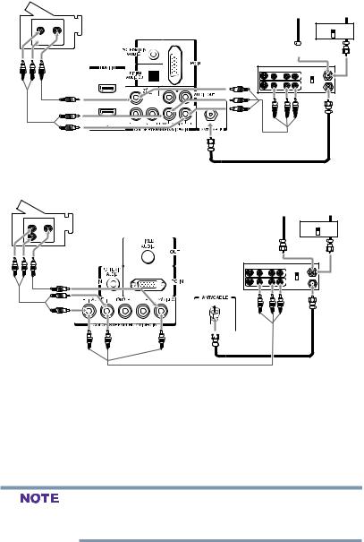
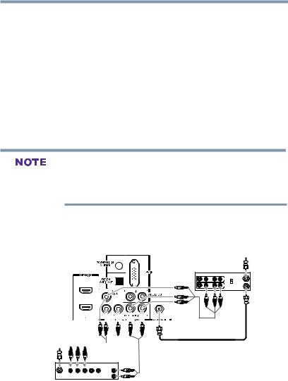
Connecting a Blu-ray™ / DVD player, satellite receiver with ColorStream® or VCR
TV back panel
From antenna
Stereo VCR
VIDEO AUDIO
IN from
CH 3 
CH 4
T |
OUT to TV |
|
From 

 satellite dish
|
AUDIO |
IN |
OUT OUT |
Satellite receiver, Blu-rayTM or DVD player
(Sample Illustration) L1350U/L2300U Series(except 58L1350U)— Connecting a Blu-ray™ /DVD player or Satellite receiver with Colorstream® (or VCR).
28 |
Connecting Your TV |
|
ConnectingaBlu-ray™/DVDplayer,satellitereceiverwithColorStream®orVCR |
||
|
TV back panel |
|
|
From antenna |
|
|
Stereo VCR |
|
|
VIDEO LAUDIOR |
|
|
IN |
IN from ANT |
|
CH 3 |
|
|
CH 4 |
|
|
OUT |
OUT to TV |
|
|
|
|
L R |
|
From
satellite dish 
|
|
|
|
AUDIO |
|
|
|
|
OUT |
Y |
PB |
PR |
|
L |
Satellite |
COMPONENT VIDEO S-VIDEO VIDEO |
R |
||
IN |
|
OUT |
OUT |
|
Satellite receiver, Blu-rayTM or DVD player
(Sample Illustration) 58L1350U—Connecting a Blu-ray™ /DVD player or Satellite receiver with Colorstream® (or VCR).
ColorStream® and composite video cables cannot be connected simultaneously.
Items needed:
vCoaxial cables
vStandardAVcables
If you have a monoVCR, connect L/MONO on theTVto your VCR’s audio out terminal using the white audio cable only.
vStandard audio cables
vComponent video cables
v You can connect the component video cables (plus audio cables) from the DVD player or satellite receiver to the COLOR STREAM HD terminal in theTV.The COLOR STREAM HD terminal can be used to display Progressive (480p, 720p) and Interlaced (480i, 1080i) scan systems.
Please note that 1080p is not supported. Check the User’s Guide of the DVD player in order to determine the best output signal available.
vIf your DVD player or satellite receiver does not have component video, connect a standardA/Vcable to the AUDIO/VIDEO terminal. If your DVD player has
HDMITM video, see “Connecting an HDMITM or DVI device to theHDMITM input” on page 30

Connecting Your TV 29
ConnectingaBlu-ray™/DVDplayer,satellitereceiverwithColorStream®orVCR
When you use ColorStream® HD or Video, switch AV input mode appropriately.
To view antenna orCable channels:
Select the ANT/CABLE video input source on theTV.*
To view the DVD player:
Turn on the DVD player. Select the COLORSTREAM HD input source on theTV.*
To view satelliteprograms using the component video connections:
Turn on the satellite receiver. Select the COLORSTREAM HD input source on theTV.*
To view theVCR orview and record antenna channels:
Turn on theVCR.Tune theVCR to the channel you want to watch. Select the VIDEO video input source on theTV.*
To record aTVprogram while watching a DVD:
Turn on theVCR.Tune theVCR to the channel to record. Select the COLORSTREAM HD input source on theTV* to view the DVD.
*To select the video input source, press the INPUT button on the remote control, see “Selecting the video input source” on page 58
The unauthorized recording, use, distribution, or revision of television programs, videotapes, DVDs, and other materials is prohibited under the Copyright Laws of the United States and other countries, and may subject you to civil and criminal liability.
30 Connecting Your TV
ConnectingananHDMITMTMorDVIor DVIdevicedevicetotheHDMITMto the HDMIinputTM input
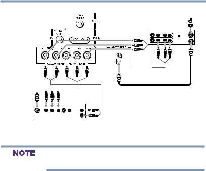
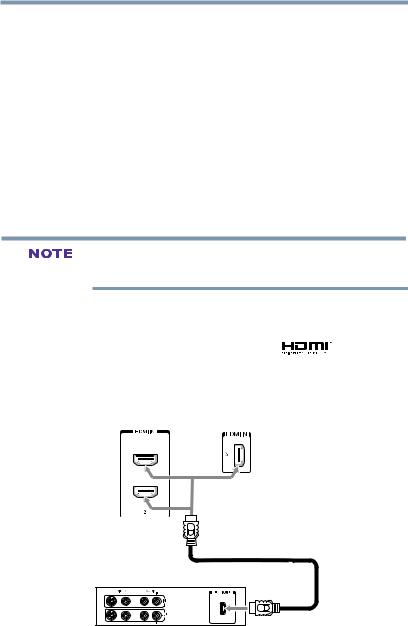
Connecting an HDMITM or DVI device to the HDMITM input
The HDMITM input on yourTVreceives digital audio and uncompressed digital video from an HDMITM source device, or uncompressed digital video from a DVI (DigitalVisual Interface) source device.
This input is designed to accept HDCP(HighBandwidth DigitalContent Protection) program material in digital form from EIA/ CEA-861-D– compliant[1] consumer electronic devices (such as a set-top box or DVD player with HDMITM or DVI output).
The HDMI™ input can accept and display various signal formats. For detailed signal specifications, see “HDMITM signal formats” on page 119.SupportedAudio format: Linear PCM, sampling rate 32/44.1/48 kHz.
To connect a computer to the HDMITM input, see “Connection to the TV’s HDMIITM terminal” on page 39
To connect an HDMITM device, you will need one HDMITM cable (typeAconnector) per HDMITM device.
vFor proper operation, it is recommended that you use an
HDMITM cable with the HDMITM Logo( |
). |
vHDMITM cables transfer both video and audio. Separate analog audio cables are not required (see illustration).
See “Setting theHDMITM audio mode” on page 56
TV back panel
HDMITM device
(Sample Illustration) L1350U/L2300U Series (except 58L1350U) —HDMITM connections
Loading...