


 Loading...
Commercial Products
Troubleshooting Guide
Groundsmaster®
345/325-D
Part No. 96904SL
INDEX
1.Product Overview GM 325-D/GM 345
2.Ford VSG-411 Gas Engine (GM 345)
3.Mitsubishi K3D Diesel Engine (GM 325-D)
4.Hydraulic Systems Hydrostatic Drive Systems
5.Electrical Systems
6.Cutting Unit Drive
7.Cutting Units
TORO GM 345 / 325 - D |
Product Overview 1 |
|
|
Product Overview
GM 300 series Groundsmaster®
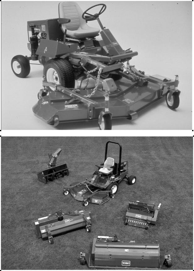
The Groundsmaster® 300 series mower is a medium size, maneuverable, commercial rotary with over twenty years of mowing experience. During those years its design has been continuously improved for optimum productivity and durability.
GM 345
Features
1.Ford 4 cylinder gas engine (45hp).
2.Sunstrand series M15 inline variable speed hydrostatic drive.
3.Hydraulic power steering and lift functions
4.Available in 2wd.
GM 325-D
Features
1.Mitsubishi 3 cylinder diesel engine (25hp).
2.Sunstrand series M15 inline variable speed hydrostatic drive.
3.Hydraulic power steering and lift functions
4.Available in 2wd and 4wd versions
Options
1.Speed control.
2.2-Post roll-over Protective Structure (ROPS).
3.4-Post ROPS with sun roof.
4.Cab with ROPS.
5.Deluxe Seat
Notes
__________________________________________________________________________________________________
__________________________________________________________________________________________________
__________________________________________________________________________________________________
__________________________________________________________________________________________________
__________________________________________________________________________________________________
__________________________________________________________________________________________________
__________________________________________________________________________________________________
__________________________________________________________________________________________________
__________________________________________________________________________________________________
2 Product Overview |
TORO GM 345 |
||
|
|
|
|
|
|
|
|
|
|
|
|
|
|
|
|
|
|
|
|
TORO GM 345 / 325 - D |
Product Overview 3 |
|
|
Attachments
1.72” Side discharge mower deck.
2.72” Rear discharge mower deck.
3.72” Guardian® Recycler® deck.
4.88” Triflex® mower deck.
5.48” Snowblower
6.Debris blower
7.Aerator
8.Plug pulverizer
9.Aero-seeder
10.V-Plow
11.Flail Mower
Notes
__________________________________________________________________________________________________
__________________________________________________________________________________________________
__________________________________________________________________________________________________
__________________________________________________________________________________________________
__________________________________________________________________________________________________
__________________________________________________________________________________________________
__________________________________________________________________________________________________
__________________________________________________________________________________________________
__________________________________________________________________________________________________

4 Ford VSG-411 Gas Engine |
TORO GM 345 |
||
|
|
|
|
|
|
|
|
|
|
|
|

TORO GM 345 |
Ford VSG-411 Gas Engine 5 |
|
|
In this section we will look at some troubleshooting procedures for the Ford Gas Engine.
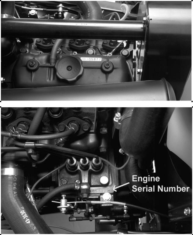
Engine Identification
The engine is identified with a decal affixed to the left side of the valve cover.
The decal contains the engine serial number.
The model number and displacement. ( i.e. 411 = 4 cyl 1.1 liter)
The special options (S.O.) number.
The engine is also stamped on the left rear top edge of the block.
This stamping includes:
A- Serial number.
B- Engine Code.
C- Engine build code: (Example 4K26)
∙The first number indicates the year.
∙The letter indicates the month in alphabetical sequence. ( A January, B February, etc.)
∙The last two numbers are the day of the month.
Complaint: Low engine power
Affect:
1.Poor cutting unit performance.
2.Poor hill climbing ability.
3.Slow hydraulic response.
4.Slow throttle response.
5.Rough running engine.
Cause:
1.Incorrect engine idle settings.
2.Misadjusted carburetor linkage.
3.Governor adjustments.
4.Internal engine problem.
5.Cracked or bad spark plugs.
6.Cracked or broken plug wires.
7.Plugged or restricted air filter.
8.Spoiled Fuel.
Notes
_______________________________________________________________________________________________________________
_______________________________________________________________________________________________________________
_______________________________________________________________________________________________________________
_______________________________________________________________________________________________________________
_______________________________________________________________________________________________________________
_______________________________________________________________________________________________________________
_______________________________________________________________________________________________________________
_______________________________________________________________________________________________________________
_______________________________________________________________________________________________________________
6 Ford VSG-411 Gas Engine |
TORO GM 345 |
||
|
|
|
|
|
|
|
|
|
|
|
|
|
|
|
|
|
|
|
|

TORO GM 345 |
Ford VSG-411 Gas Engine 7 |
|
|
Troubleshooting:
High and Low Idle Checks.
The idle settings are important for the proper operation and long life of the machine.
Affects of incorrect idle speeds:
1.High idle too slow:
∙Low power. (engine not running at full speed)
∙Slow transport speed. (hydrostatic transmission input shaft speed too slow)
∙Poor Quality of cut. (Blade RPM and tip speed too slow)
2.High idle too fast:
∙Internal engine damage. (Excessive engine RPM can damage crankshaft and bearings)
∙Hydrostatic transmission damage. (insufficient lubrication for high input shaft speeds)
∙Engine overheating.
3.Low idle too slow:
∙Hydrostatic transmission damage.(lack of lubrication)
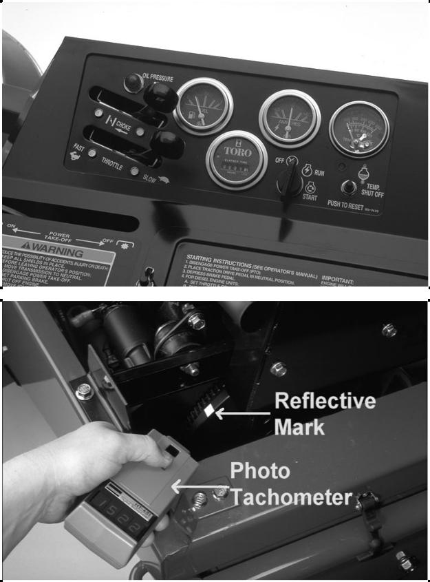
Checking Idle Speeds
1.Run the engine until it reaches normal operating temperature.
2.Move the throttle lever to the low idle position.
∙Low idle should be 1500 ± 100.
3. Open the throttle to the high idle position.
∙High idle should be 3200 ± 100.
NOTE: If high or low idle is incorrect, refer to the Operators manual for correct adjustment procedures.
Notes
_______________________________________________________________________________________________________________
_______________________________________________________________________________________________________________
_______________________________________________________________________________________________________________
_______________________________________________________________________________________________________________
_______________________________________________________________________________________________________________
_______________________________________________________________________________________________________________
_______________________________________________________________________________________________________________
_______________________________________________________________________________________________________________
_______________________________________________________________________________________________________________
8 Ford VSG-411 Gas Engine |
TORO GM 345 |
||
|
|
|
|
|
|
|
|
|
|
|
|
|
|
|
|
|
|
|
|
|
TORO GM 345 |
Ford VSG-411 Gas Engine 9 |
|
|
|
|
|
|
|
|
|
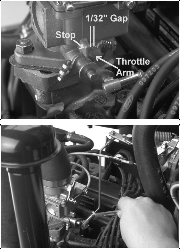
Correction:
Carburetor linkage adjustment.
1.With the engine shut off, move the throttle control to the FAST position.
2.Check the gap between the throttle arm and the stop on the carburetor base. The correct gap is 1/32” (0.78mm).
3.If the gap is not correct adjust the throttle rod by turning the ball joint until the proper gap is attained.
This adjustment insures that the carburetor throttle plate can fully open under a load, but the linkage will not bottom out against the stop.
Notes
_______________________________________________________________________________________________________________
_______________________________________________________________________________________________________________
_______________________________________________________________________________________________________________
_______________________________________________________________________________________________________________
_______________________________________________________________________________________________________________
_______________________________________________________________________________________________________________
_______________________________________________________________________________________________________________
_______________________________________________________________________________________________________________
_______________________________________________________________________________________________________________
10 Ford VSG-411 Gas Engine |
TORO GM 345 |
||
|
|
|
|
|
|
|
|
|
|
|
|
|
|
|
|
|
|
|
|

TORO GM 345 |
Ford VSG-411 Gas Engine 11 |
|
|
|
|
The final adjustments are made with the engine running. To guard against possible personal injury, engage the parking brake and keep hands, feet, face and other parts of the body away from the fan or other moving parts.
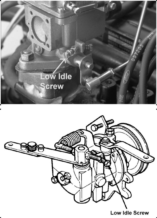
Low Idle Adjustment.
1.Start the engine and move the throttle to the slow position.
2.Manually rotate the throttle arm closed until it contacts the stop.
3.Check the idle speed and adjust carburetor idle speed screw, if necessary to attain 1350 ± 50 rpm.
∙This prevents the throttle plate from being able to bottom out in the carburetor barrel.
4.Release the throttle arm, loosen the jam nut on the governor low idle speed screw and adjust it to attain 1500 ± 100 rpm.
∙This sets the actual engine idle speed.
Notes
_______________________________________________________________________________________________________________
_______________________________________________________________________________________________________________
_______________________________________________________________________________________________________________
_______________________________________________________________________________________________________________
_______________________________________________________________________________________________________________
_______________________________________________________________________________________________________________
_______________________________________________________________________________________________________________
_______________________________________________________________________________________________________________
_______________________________________________________________________________________________________________
12 Ford VSG-411 Gas Engine |
TORO GM 345 |
||
|
|
|
|
|
|
|
|
|
|
|
|
|
|
|
|
|
|
|
|
TORO GM 345 |
Ford VSG-411 Gas Engine 13 |
|
|
|
|
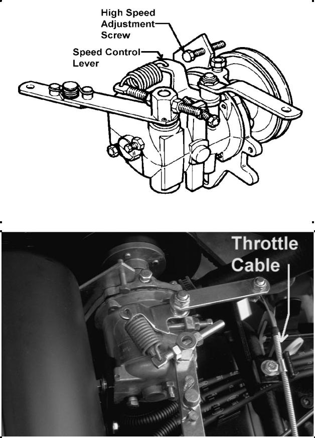
High Idle Adjustment.
1. Slowly move the throttle to the FAST position until the engine reaches 3200 ± 100. Shut off the engine. Adjust the high speed adjustment screw until it contacts the speed control lever.
IMPORTANT: Do not overspeed the engine because transmission damaged could occur.
2. If 3200 rpm can not be attained, check the throttle cable adjustment.
∙The governor arm must not contact the cable cover when the unit is at high idle.
∙If the governor arm contacts the cable, loosen the retaining bolt and move the cable.
3.If the throttle lever on the instrument panel will not stay in the fast position, remove the panel cover and tighten the nut and capscrew at the base of the throttle lever.
Notes
_______________________________________________________________________________________________________________
_______________________________________________________________________________________________________________
_______________________________________________________________________________________________________________
_______________________________________________________________________________________________________________
_______________________________________________________________________________________________________________
_______________________________________________________________________________________________________________
_______________________________________________________________________________________________________________
_______________________________________________________________________________________________________________
_______________________________________________________________________________________________________________
14 Ford VSG-411 Gas Engine |
TORO GM 345 |
||
|
|
|
|
|
|
|
|
|
|
|
|
|
|
|
|
|
|
|
|
TORO GM 345 |
Ford VSG-411 Gas Engine 15 |
|
|
|
|
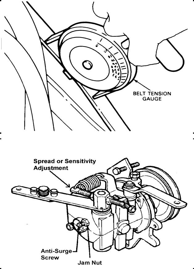
Anti-Surge Adjustment.
1.Move the throttle rapidly from SLOW to FAST. The engine should not surge, if the engine surges proceed to step 2.
2.Check the V-belts from the engine to the governor pulley and assure that they are tight.
∙The belt is adjusted to 45 lbs of tension on a belt gauge for a new belt.
∙A used belt is re-tensioned to 28 lbs.
∙The replacement belt PN is 67-8510.
3.Loosen the jam nut that retains the anti-surge screw. Rotate the screw clockwise 1/8 of a turn at a time until the surging stops.
4.Check the low and high idle speed to be sure that there is no change in the initial settings. If the idle speed has increased, the anti-surge screw has been turned in too far and it must be backed out.
Other things to check when engine surges:
A.Carburetor too rich or lean.
B.Binding in the throttle linkage.
C.Governor worn internally.
Governor Spread or Sensitivity Adjustment.
Governor spread is the difference between the no load governed speed, and the full load speed. For the governor to work correctly this spread should be 5 to 10 percent.
To check governor spread, check and record the no-load high idle speed and compare this to the loaded high idle speed.
To increase the spread adjust the adjustment bolt to position the spring farther away from the lever hub. To decrease the spread position the spring closer to the hub.
Notes
_______________________________________________________________________________________________________________
_______________________________________________________________________________________________________________
_______________________________________________________________________________________________________________
_______________________________________________________________________________________________________________
_______________________________________________________________________________________________________________
_______________________________________________________________________________________________________________
_______________________________________________________________________________________________________________
_______________________________________________________________________________________________________________
_______________________________________________________________________________________________________________
16 Ford VSG-411 Gas Engine |
TORO GM 345 |
||
|
|
|
|
|
|
|
|
|
|
|
|
|
|
|
|
|
|
|
|
TORO GM 345 |
Ford VSG-411 Gas Engine 17 |
|
|
|
|
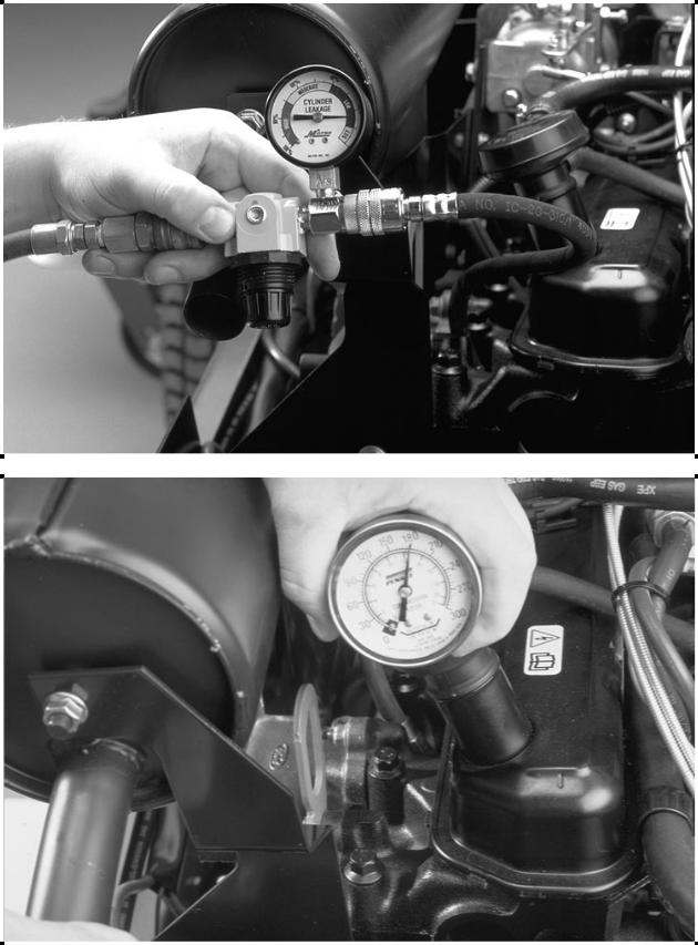
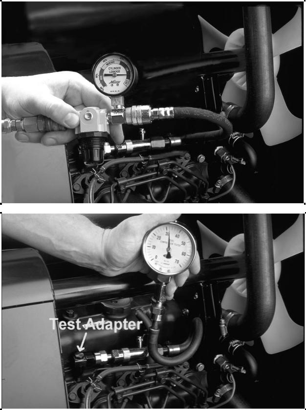
Cylinder Leakage Test.
The cylinder leakage test can locate the following problems:
1.Leaking intake valves.
∙Air leaking from carburetor.
2.Leaking exhaust valves.
∙Air leaking from muffler.
3.Leaking cylinder head gaskets.
∙Air leaking externally by head gasket.
4.Worn piston rings.
∙Air leaking from breather or dipstick tube.
NOTE. There will always be some air leakage past the rings. Use the tester gauge to determine the severity of the leak.
With the engine rotated until the piston is at the top of travel on the compression stroke. The cylinder is filled with air through the spark plug opening, The leakage tester will display the percentage of air lost when the piston is at the top part of the compression stroke.
A cylinder leakage of 25 percent or less is acceptable.
Compression Testing.
1.Make sure the batteries are fully charged.
2.Remove all the spark plugs.
3.Set the throttle to high idle and the choke in the wide open position.
4.Install an automotive type (0-300 PSI) compression gauge.
5.Using an auxiliary starting switch, crank the engine (with the ignition switch off) at least five compression strokes and record the highest reading.
6.Normal compression should read 170 to 185 PSI depending on engine temperature and cranking speed.
7.Repeat the test on each cylinder.
If one or more cylinders read low, and a cylinder leakage tester is not available, squirt approximately one tablespoon of engine oil on top of the pistons in the low reading cylinders.
Repeat compression test on these cylinders.
1.If the compression improves considerably, the piston rings are at fault.
2.If the compression does not improve, the valves are sticking or seating poorly.
3.If two adjacent cylinders indicate low compression pressures and squirting oil in the pistons does not increase the compression, the cause may be a leaking cylinder head gasket between the two cylinders.
Notes
_______________________________________________________________________________________________________________
_______________________________________________________________________________________________________________
_______________________________________________________________________________________________________________
_______________________________________________________________________________________________________________
_______________________________________________________________________________________________________________
_______________________________________________________________________________________________________________
_______________________________________________________________________________________________________________
_______________________________________________________________________________________________________________
_______________________________________________________________________________________________________________

18 Ford VSG-411 Gas Engine |
TORO GM 345 |
|
|
|
|
Special tools
1. Electric tach.
∙OTC P/N - OEM1386 or equivalent.
2. Photo tach.
∙OTC P/N - OEM1057 or equivalent.
3. Belt tension gauge
∙OTC P/N - OEM1294 or equivalent
4. Cylinder leakage tester.
∙OTC P/N - TOR4075 or equivalent.
5. Compression tester.
∙0 - 300 psi.
∙OTC P/N - OEM1072, OEM 1073 or equivalent.
Helpful Hints
1.All engine RPM checks should be performed with the engine warm.
2.Governor oil is the same oil as is used in the crankcase
3.Cylinder leakage can identify the location and the extent of an internal engine problem
∙Cylinder leakage of 25 percent or less is acceptable
4.When checking engine compression the throttle and the choke must be fully open to insure an accurate reading
5.Normal engine compression at cranking speed is 185 PSI.
6.The actual compression reading is not as important as the relationship between all the cylinder readings.
7.Part Numbers
∙Engine oil filter, Motorcraft P/N FL.400-A.
∙Fuel filter, Motorcraft P/N FG795A.
∙Air filter Toro P/N 27-7110
TORO GM 345 |
Ford VSG-411 Gas Engine 19 |
|
|
|
|
Review Questions
1. Proper high idle setting is:
a.2800 ± 50 RPM
b.3200 ± 100 RPM
c.3000 ± 25 RPM
d.1500 ± 100 RPM
2.The final high idle adjustment is made at the carburetor.
a.True
b.False
3. The recommended compression gauge is:
a.0 - 100 PSI
b.0 - 200 PSI
c.0 - 300 PSI
d.200 - 400 PSI
4. Normal engine compression is:
a.100 PSI
b.205 PSI
c.185 PSI
d.415 PSI
5. Adding oil to a cylinder with a bad intake valve will increase the compression reading of the cylinder.
a.True
b.False
6.When performing a leakage test, air leaking from the breather indicates :
a.Leaking intake valve.
b.Leaking exhaust valve.
c.Leaking head gasket.
d.A normal situation
Notes
_______________________________________________________________________________________________________________
_______________________________________________________________________________________________________________
_______________________________________________________________________________________________________________
_______________________________________________________________________________________________________________
_______________________________________________________________________________________________________________
_______________________________________________________________________________________________________________
_______________________________________________________________________________________________________________
_______________________________________________________________________________________________________________
_______________________________________________________________________________________________________________
20 Mitsubishi K3D Diesel Engine |
TORO GM 325-D |
|||
|
|
|
|
|
|
|
|
|
|
|
|
|
|
|
|
|
|
|
|
|
|
|
|
|

TORO GM 325-D |
Mitsubishi K3D Diesel Engine 21 |
|
|
In this section we will look at some troubleshooting procedures for the Mitsubishi Diesel Engine.
Engine Identification
The engine model number and serial number is listed on a decal on the valve cover.
The engine serial number is also stamped on the injection pump mounting surface.
Complaint: Low engine power
Affect:
1.Poor cutting unit performance.
2.Poor hill climbing ability.
3.Slow hydraulic response.
4.Slow throttle response.
5.Rough running engine.
Cause:
1.Incorrect engine idle settings.
2.Fuel injection problems.
∙Incorrect injection timing.
∙Incorrect injector spray pattern.
3.Internal engine problem.
4.Poor or contaminated fuel.
5.Restricted air filter or intake.
Notes
________________________________________________________________________________________________________________
________________________________________________________________________________________________________________
________________________________________________________________________________________________________________
________________________________________________________________________________________________________________
________________________________________________________________________________________________________________
________________________________________________________________________________________________________________
________________________________________________________________________________________________________________
________________________________________________________________________________________________________________
________________________________________________________________________________________________________________
22 Mitsubishi K3D Diesel Engine |
TORO GM 325-D |
||||
|
|
|
|
|
|
|
|
|
|
|
|
|
|
|
|
|
|
|
|
|
|
|
|
|
|
|
|
|
|

TORO GM 325-D |
Mitsubishi K3D Diesel Engine 23 |
|
|
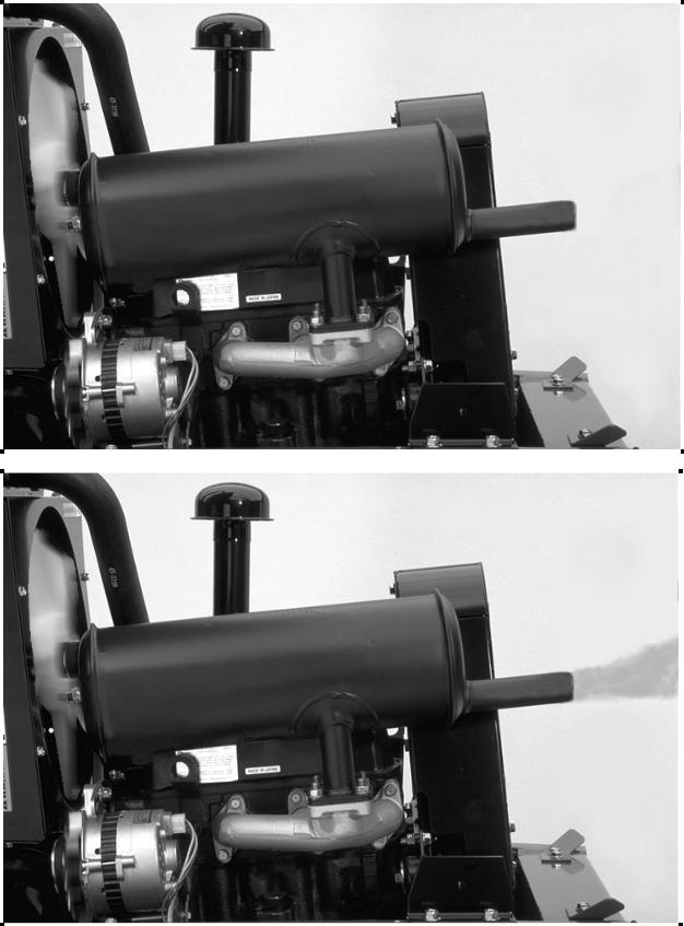
Analyzing Diesel Exhaust Smoke.
The exhaust from a diesel engine can provide information about the running condition of the engine. A normally operating engine will have exhaust that is clear to a slight brownish/gray color.
1.Black Smoke.
∙Insufficient air.
(Plugged or dirty air filter)
∙Excessive fuel.
(Leaking injection nozzles)
(Over fueled injection pump setting)
∙Engine Overloaded. (Excessive load on engine)
2.Blue Smoke.
∙High engine oil consumption. (Worn rings or valve guides) (Plugged crankcase breather)
3.White Smoke.
∙Water in combustion chamber. (Leaking head gasket)
(Cracked cylinder head or cylinder wall)
White smoke can also be caused by the following:
∙Incorrect injection timing.
∙Low compression. (Incomplete combustion)
∙Low cylinder temperature. (Faulty glow plugs)
(low ambient air temperature)
Note: White smoke may dissipate when engine warms up.
Notes
________________________________________________________________________________________________________________
________________________________________________________________________________________________________________
________________________________________________________________________________________________________________
________________________________________________________________________________________________________________
________________________________________________________________________________________________________________
________________________________________________________________________________________________________________
________________________________________________________________________________________________________________
________________________________________________________________________________________________________________
________________________________________________________________________________________________________________
24 Mitsubishi K3D Diesel Engine |
TORO GM 325-D |
||||
|
|
|
|
|
|
|
|
|
|
|
|
|
|
|
|
|
|
|
|
|
|
|
|
|
|
|
|
|
|
Loading...