


 Loading...
Part No. 92784SL, Rev. E
Service Manual
Greensmaster® 3100/3050
Preface
This publication provides the service technician with information for troubleshooting, testing, and repair of major systems and components on the Greensmaster 3100 and 3050.
REFER TO THE TRACTION UNIT, CUTTING UNIT AND ACCESSORY OPERATOR’S MANUALS FOR OPERATING, MAINTENANCE AND ADJUSTMENT INSTRUCTIONS. Space is provided at the end of Chapter 2 in this publication to insert the Operator’s Manuals and Parts Catalogs for your machine. Replacement Operator’s Manuals are available by sending complete Model and Serial Number of traction unit and cutting unit to:
The Toro Company
8111 Lyndale Avenue South
Minneapolis, MN 55420
The Toro Company reserves the right to change product specifications or this publication without notice.
This safety symbol means DANGER, WARNING, or CAUTION, PERSONAL SAFETY INSTRUCTION. When you see this symbol, carefully read the instructions that follow. Failure to obey the instructions may result in personal injury.
NOTE: A NOTE will give general information about the correct operation, maintenance, service, testing or repair of the machine.
IMPORTANT: The IMPORTANT notice will give important instructions which must be followed to prevent damage to systems or components on the machine.
© The Toro Company - 1991, 1998, 2002, 2004, 2005
This page is intentionally blank.

Table Of Contents
Chapter 1 - Safety
Safety Instructions . . . . . . . . . . . . . . . . . . . . . . . . 1 - 1
Chapter 2 - Product Records and Manuals
Product Records. . . . . . . . . . . . . . . . . . . . . . . . . . 2 - 1
Equivalents and Conversions. . . . . . . . . . . . . . . . 2 - 2
Torque Specifications . . . . . . . . . . . . . . . . . . . . . . 2 - 3
Maintenance Interval Charts. . . . . . . . . . . . . . . . . 2 - 4
Equipment Operational and
Service Historical Report Record
Chapter 3 - Engine
Specifications . . . . . . . . . . . . . . . . . . . . . . . . . . . . 3 - 1
Adjustments . . . . . . . . . . . . . . . . . . . . . . . . . . . . . 3 - 2
Repairs . . . . . . . . . . . . . . . . . . . . . . . . . . . . . . . . . 3 - 5
BRIGGS & STRATTON VANGUARD V-TWIN OHV
SERVICE & REPAIR INSTRUCTIONS
Chapter 4 - Hydraulic System
Specifications . . . . . . . . . . . . . . . . . . . . . . . . . . . . 4 - 2
General Information . . . . . . . . . . . . . . . . . . . . . . . 4 - 3
Hydraulic Flow Diagrams . . . . . . . . . . . . . . . . . . . 4 - 5
Hydraulic Schematic. . . . . . . . . . . . . . . . . . . . . . 4 - 12
Special Tools . . . . . . . . . . . . . . . . . . . . . . . . . . . 4 - 13
Troubleshooting . . . . . . . . . . . . . . . . . . . . . . . . . 4 - 16
Testing . . . . . . . . . . . . . . . . . . . . . . . . . . . . . . . . 4 - 27
Adjustments . . . . . . . . . . . . . . . . . . . . . . . . . . . . 4 - 36
Repairs . . . . . . . . . . . . . . . . . . . . . . . . . . . . . . . . 4 - 39
Chapter 5 - Electrical System
Wiring Schematic . . . . . . . . . . . . . . . . . . . . . . . . . 5 - 2
Turf Guardian Leak Detection System . . . . . . . . . 5 - 3
Special Tools. . . . . . . . . . . . . . . . . . . . . . . . . . . . . 5 - 4
Troubleshooting . . . . . . . . . . . . . . . . . . . . . . . . . . 5 - 6
Testing . . . . . . . . . . . . . . . . . . . . . . . . . . . . . . . . . 5 - 9
Repairs . . . . . . . . . . . . . . . . . . . . . . . . . . . . . . . . 5 - 13
Chapter 6 - Wheels, Steering and Brakes
Specifications . . . . . . . . . . . . . . . . . . . . . . . . . . . . 6 - 2
Adjustments . . . . . . . . . . . . . . . . . . . . . . . . . . . . . 6 - 3
Repairs . . . . . . . . . . . . . . . . . . . . . . . . . . . . . . . . . 6 - 4
Chapter 7 - 4 Bolt Adjust Cutting Units
Specifications . . . . . . . . . . . . . . . . . . . . . . . . . . . . 7 - 2
Special Tools. . . . . . . . . . . . . . . . . . . . . . . . . . . . . 7 - 3
Troubleshooting . . . . . . . . . . . . . . . . . . . . . . . . . . 7 - 5
Set Up and Adjustments . . . . . . . . . . . . . . . . . . . . 7 - 7
Repairs . . . . . . . . . . . . . . . . . . . . . . . . . . . . . . . . 7 - 15
Chapter 8 - Single Point Adjust Cutting Units
Specifications . . . . . . . . . . . . . . . . . . . . . . . . . . . . 8 - 3
Special Tools. . . . . . . . . . . . . . . . . . . . . . . . . . . . . 8 - 4
Troubleshooting . . . . . . . . . . . . . . . . . . . . . . . . . . 8 - 6
Set Up and Adjustments . . . . . . . . . . . . . . . . . . . . 8 - 6
Repairs . . . . . . . . . . . . . . . . . . . . . . . . . . . . . . . . 8 - 19
Chapter 9 - Grooming Reel Cutting Units
Specifications . . . . . . . . . . . . . . . . . . . . . . . . . . . . 9 - 3
Special Tools. . . . . . . . . . . . . . . . . . . . . . . . . . . . . 9 - 4
Troubleshooting . . . . . . . . . . . . . . . . . . . . . . . . . . 9 - 6
Set Up and Adjustments . . . . . . . . . . . . . . . . . . . 9 - 10
Repairs . . . . . . . . . . . . . . . . . . . . . . . . . . . . . . . . 9 - 21
Chapter 10 - Dual Point Adjust Cutting Units
Specifications . . . . . . . . . . . . . . . . . . . . . . . . . . . 10 - 2
Special Tools . . . . . . . . . . . . . . . . . . . . . . . . . . . 10 - 3
Troubleshooting . . . . . . . . . . . . . . . . . . . . . . . . . 10 - 5
Setup and Adjustments . . . . . . . . . . . . . . . . . . . .10 - 7
Repairs . . . . . . . . . . . . . . . . . . . . . . . . . . . . . . . . 10 - 8
Greensmaster® 3100 |
Rev. D |
This page is intentionally blank.
|
|
|
Chapter 1 |
|
|
|
Safety |
|
|
|
|
Table of Contents |
|
|
|
SAFETY INSTRUCTIONS . . . . . . . . . . . . . . . . . . . . |
1 |
While Doing Maintenance, Troubleshooting, |
|
Before Operating. . . . . . . . . . . . . . . . . . . . . . . . . |
1 |
Testing, Adjustments or Repairs |
. . . . . . . . . . . . . 3 |
While Operating. . . . . . . . . . . . . . . . . . . . . . . . . . |
2 |
|
|
Safety Instructions
The Greensmaster 3100 has been tested and certified for compliance with the B71.4-1984 specifications of the American National Standards Institute (ANSI) for riding mowers when 40 lbs. of ballast is added to rear wheel. Hazard control and accident prevention are dependent upon the awareness, concern, and proper training of the personnel involved in the operation, transport, maintenance and storage of the machine. Improper use or maintenance of the machine can result in personal injury or death. To reduce the potential for injury or death, comply with the following safety instructions.
CAUTION
Obey the following safety instructions. Read and understand these instructions before operating the Greensmaster 3100 or doing maintenance, troubleshooting, testing, adjustments or repairs. Failure to comply with the safety instructions may result in personal injury.
Before Operating
1. Read and understand the Operator’s Manual before starting, operating, maintaining or repairing the machine. Replacement Operator’s Manuals are available by sending complete Model and Serial Number of traction unit and cutting units to:
The Toro Company
8111 Lyndale Avenue South
Minneapolis, MN 55420
Use the Model and Serial Number when referring to your machine. If you have questions about this Service Information, please contact:
The Toro Company
Commercial Service Department
8111 Lyndale Avenue South
Minneapolis, MN 55420
2. Never allow children to operate the machine or adults to operate it without proper instruction.
3.Become familiar with the controls and know how to stop the machine and engine quickly.
4.Keep all shields, safety devices and decals in place. If a shield, safety device or decal is defective or damaged, repair or replace it before operating the machine.
5.Always wear substantial shoes. Do not operate machine wearing sandals, tennis shoes, sneakers or when barefoot. Do not wear loose fitting clothing that could get caught in moving parts and possibly cause personal injury.
6.Wearing safety glasses, safety shoes, long pants and a helmet is advisable and required by some local ordinances and insurance regulations.
7.Make sure the work area is clear of objects which might be picked up and thrown by the reels.
Greensmaster® 3100 |
Page 1 - 1 |
Safety Instructions |

8.Do not carry passengers on the machine. Keep everyone, especially children and pets, away from the areas of operation.
9.Since gasoline is highly flammable, handle it carefully:
A.Use an approved fuel container.
B.Do not remove fuel tank cap while engine is hot or running.
C.Do not smoke while handling fuel.
D.Fill fuel tank outdoors and only to within an inch (25 mm) from the top of the tank, not the filler neck. Do not overfill.
E.Wipe up any spilled fuel.
While Operating
10.Do not run engine in a confined area without adequate ventilation. Exhaust is hazardous and could be deadly.
11.Sit on the seat when starting and operating the machine.
12.Check interlock switches daily for proper operation. If a switch fails, replace it before operating the machine. The interlock system is for your protection, so do not bypass it. Replace all interlock switches every two years.
13.To start the engine:
A.Sit on the seat, depress lift pedal and release it to disengage cutting units.
B.Verify that traction system is in neutral.
C.Verify that parking brake is set.
D.Proceed to start the engine.
14.Using the machine demands attention. To prevent loss of control:
A.Mow only in daylight or when there is good artificial light.
B.Watch for holes or other hidden hazards.
C.Be extremely careful when operating close to sand traps, ditches, creeks, steep hillsides or other hazards.
D.Reduce speed when making sharp turns. Avoid sudden stops and starts.
E.Look to the rear to assure no one is behind the machine before backing up.
F.Watch for traffic when near or crossing roads. Always yield the right-of-way.
G.Apply the service brakes when going down hill to keep forward speed slow and to maintain control of the machine.
15.Keep hands, feet and clothing away from moving parts and the reels. The grass baskets must be in place during operation of the reels or thatchers for maximum safety. Shut the engine off before emptying the baskets.
16.Raise cutting units when driving from one work area to another.
17.Do not touch engine, muffler or exhaust pipe while engine is running or soon after it is stopped. These areas could be hot enough to cause burns.
18.Stay clear of rotating screen at side of engine to prevent direct contact with body or clothing.
19.If cutting unit strikes a solid object or vibrates abnormally, stop immediately, turn engine off, set parking brake and wait for all motion to stop. Inspect for damage. If reel or bedknife is damaged, repair or replace it before operating.
20.Before getting off the seat:
A.Move shift selector to N (neutral).
B.Depress the lift pedal to raise the cutting units, wait for the reels to stop spinning and release lift pedal.
C.Set the parking brake.
E.Stop engine and remove key from switch.
21.Traverse slopes carefully. Do not start or stop suddenly when traveling uphill or downhill.
22.Operator must be skilled and trained in how to drive on hillsides. Failure to use caution on slopes or hills may cause loss of control and vehicle to tip or roll, possibly resulting in personal injury or death.
23.If engine stalls or loses headway and cannot make it to the top of a slope, do not turn machine around. Always back slowly straight down the slope.
24.DO NOT TAKE AN INJURY RISK! When a person or pet appears unexpectedly in or near the mowing area, STOP MOWING. Careless operation, combined with terrain angles, ricochets, or improperly positioned guards can lead to thrown object injuries. Do not resume mowing until area is cleared.
25.Whenever machine is left unattended, make sure cutting units are fully raised and reels are not spinning, key is removed from ignition switch and parking brake is set.
Safety Instructions |
Page 1 - 2 |
Greensmaster® 3100 |

While Doing Maintenance, Troubleshooting, Testing, Adjustments or Repairs
26.Before servicing or making adjustments to the machine, stop the engine, remove key from ignition switch and pull wires off spark plugs to prevent accidental starting of the engine.
27.Make sure the entire machine is properly maintained and in good operating condition. Frequently tighten all nuts bolts. and screws.
28.Make sure all hydraulic line connectors are tight and all hydraulic hoses and lines are in good condition before applying pressure to the system.
29.Keep body and hands away from pin hole leaks or nozzles that eject high pressure hydraulic fluid. Use cardboard or paper to find hydraulic leaks. Hydraulic fluid escaping under pressure can penetrate the skin and cause injury. Fluid accidentally injected into the skin must be surgically removed within a few hours by a doctor or gangrene may occur.
30.Before disconnecting or performing any work on the hydraulic system, all pressure in system must be relieved by stopping engine and lowering cutting units and attachments to the ground.
31.To reduce potential fire hazard, keep engine area free of excessive grease, grass, leaves and dirt. Do not use flammable solvents for cleaning parts. Do not use diesel fuel, kerosene or gasoline.
32.If the engine must be running to perform an inspection or procedure, use extreme caution. Always use two people, with the operator at the controls able to see the person doing the inspection or procedure. Keep hands, feet, clothing, and body away from cutting units and other moving parts.
33.Do not overspeed the engine by changing governor settings. Maximum governed engine speed should be 2850 rpm.
34.Shut engine off before checking or adding oil to the engine crankcase.
35.Be sure you understand a service procedure before working on the machine. Unauthorized modifications to the machine may impair the function, safety and life of the machine. If major repairs are ever needed, or assistance is desired, contact your TORO Distributor.
36.Wear safety glasses, goggles or a face shield to prevent possible eye injury when using compressed air for cleaning or drying components.
37.When changing attachments or performing other service, use the correct blocks and hoists. Always use jackstands to safely support the machine when it is raised by a jack or hoist.
38.Do not use your hand to prevent cutting unit reel from turning while servicing; this can result in personal injury. Use a 1/2 in. thick x 3 in. wide x 8 in. long piece of hardwood inserted into front of cutting unit between reel blades.
39.For optimum performance and safety, use genuine Toro replacement parts and accessories. Replacement parts and accessories made by other manufacturers could be dangerous and my void the product warranty of The Toro Company.
Greensmaster® 3100 |
Page 1 - 3 |
Safety Instructions |
Safety Instructions |
Page 1 - 4 |
Greensmaster® 3100 |

Chapter 2
Product Records and Manuals
Table of Contents
PRODUCT RECORD FORM . . . . . . . . . . . . . . . . . . 1 EQUIVALENTS AND CONVERSIONS . . . . . . . . . . 2 Decimal and Millimeter Equivalents . . . . . . . . . . 2 U.S. to Metric Conversions . . . . . . . . . . . . . . . . . 2
TORQUE SPECIFICATIONS . . . . . . . . . . . . . . . . . . 3
Capscrew Markings and Torque Values - U.S. . . 3
Capscrew Markings and Torque Values - Metric . 3
Product Records
Insert Operator's Manual and Parts Catalog for your Greensmaster 3100 or 3050 at the end of this chapter. Refer to Operator's Manual for recommended maintenance intervals. Additionally, insert Installation Instructions, Operator's Manuals and Parts Catalogs for any accessories that have been installed on your Greensmaster 3100 or 3050 at the end of this section.
Greensmaster® 3100 |
Page 2 - 1 Rev..DB |
Product Records |

Equivalents and Conversions
Decimal and Millimeter Equivalents
___________________________________________________________________________________________________
Fractions Decimals mm Fractions Decimals mm
___________________________________________________________________________________________________
1/64 |
0.015625 |
— 0.397 |
33/64 |
0.515625 |
— 13.097 |
1/32 ––––– |
0.03125 |
— 0.794 |
17/32 –––– |
0.53125 |
— 13.494 |
3/64 |
0.046875 |
— 1.191 |
35/64 |
0.546875 |
— 13.891 |
1/16 –––––––––––– |
0.0625 |
— 1.588 |
9/16 –––––––––––– |
0.5625 |
— 14.288 |
5/64 |
0.078125 |
— 1.984 |
37/64 |
0.578125 |
— 14.684 |
3/32 ––––– |
0.9375 |
— 2.381 |
19/32 –––– |
0.59375 |
— 15.081 |
7/64 |
0.109275 |
— 2.778 |
39/64 |
0.609375 |
— 15.478 |
1/8 ––––––––––––– |
0.1250 |
— 3.175 |
5/8 ––––––––––––– |
0.6250 |
— 15.875 |
9/64 |
0.140625 |
— 3.572 |
41/64 |
0.640625 |
— 16.272 |
5/32 ––––– |
0.15625 |
— 3.969 |
21/32 –––– |
0.65625 |
— 16.669 |
11/64 |
0.171875 |
— 4.366 |
43/64 |
0.671875 |
— 17.066 |
3/16 –––––––––––– |
0.1875 |
— 4.762 |
11/16 ––––––––––– |
0.6875 |
— 17.462 |
13/64 |
0.203125 |
— 5.159 |
45/64 |
0.703125 |
— 17.859 |
7/32 ––––– |
0.21875 |
— 5.556 |
23/32 –––– |
0.71875 |
— 18.256 |
15/64 |
0.234375 |
— 5.953 |
47/64 |
0.734375 |
— 18.653 |
1/4 ––––––––––––– |
0.2500 |
— 6.350 |
3/4 ––––––––––––– |
0.7500 |
— 19.050 |
17/64 |
0.265625 |
— 6.747 |
49/64 |
0.765625 |
— 19.447 |
9/32 ––––– |
0.28125 |
— 7.144 |
25/32 –––– |
0.78125 |
— 19.844 |
19/64 |
0.296875 |
— 7.541 |
51/64 |
0.796875 |
— 20.241 |
5/16 –––––––––––– |
0.3125 |
— 7.541 |
13/16 ––––––––––– |
0.8125 |
— 20.638 |
21/64 |
0.328125 |
— 8.334 |
53/64 |
0.828125 |
— 21.034 |
11/32 –––– |
0.34375 |
— 8.731 |
27/32 –––– |
0.84375 |
— 21.431 |
23/64 |
0.359375 |
— 9.128 |
55/64 |
0.859375 |
— 21.828 |
3/8 ––––––––––––– |
0.3750 |
— 9.525 |
7/8 ––––––––––––– |
0.8750 |
— 22.225 |
25/64 |
0.390625 |
— 9.922 |
57/64 |
0.890625 |
— 22.622 |
13/32 –––– |
0.40625 |
— 10.319 |
29/32 –––– |
0.90625 |
— 23.019 |
27/64 |
0.421875 |
— 10.716 |
59/64 |
0.921875 |
— 23.416 |
7/16 –––––––––––– |
0.4375 |
— 11.112 |
15/16 ––––––––––– |
0.9375 |
— 23.812 |
29/64 |
0.453125 |
— 11.509 |
61/64 |
0.953125 |
— 24.209 |
15/32 –––– |
0.46875 |
— 11.906 |
31/32 –––– |
0.96875 |
— 24.606 |
31/64 |
0.484375 |
— 12.303 |
63/64 |
0.984375 |
— 25.003 |
1/2 ––––––––––––– |
0.5000 |
— 12.700 |
1 –––––––––––––– |
1.000 |
— 25.400 |
1 mm = 0.03937 in. |
|
0.001 in. = 0.0254 mm |
|
||
___________________________________________________________________________________________________
U.S to Metric Conversions
___________________________________________________________________________________________________
To Convert Into Multiply By
___________________________________________________________________________________________________
Linear |
Miles |
Kilometers |
1.609 |
Measurement |
Yards |
Meters |
0.9144 |
|
Feet |
Meters |
0.3048 |
|
Feet |
Centimeters |
30.48 |
|
Inches |
Meters |
0.0254 |
|
Inches |
Centimeters |
2.54 |
|
Inches |
Millimeters |
25.4 |
___________________________________________________________________________________________________
Area |
Square Miles |
Square Kilometers |
2.59 |
|
Square Feet |
Square Meters |
0.0929 |
|
Square Inches |
Square Centimeters |
6.452 |
|
Acre |
Hectare |
0.4047 |
___________________________________________________________________________________________________
Volume |
Cubic Yards |
Cubic Meters |
0.7646 |
|
Cubic Feet |
Cubic Meters |
0.02832 |
|
Cubic Inches |
Cubic Centimeters |
16.39 |
___________________________________________________________________________________________________
Weight |
Tons (Short) |
Metric Tons |
0.9078 |
|
Pounds |
Kilograms |
0.4536 |
|
Ounces (Avdp.) |
Grams |
28.3495 |
___________________________________________________________________________________________________
Pressure Pounds/Sq. In. Kilopascal 6.895
___________________________________________________________________________________________________
Work |
Foot-pounds |
Newton-Meters |
1.356 |
|
Foot-pounds |
Kilogram-Meters |
0.1383 |
|
Inch-pounds |
Kilogram-Centimeters |
1.152144 |
___________________________________________________________________________________________________
Liquid Volume |
Quarts |
Liters |
0.9463 |
|
Gallons |
Liters |
3.785 |
___________________________________________________________________________________________________
Liquid Flow Gallons/Minute Liters/Minute 3.785
___________________________________________________________________________________________________
Temperature |
Fahrenheit |
Celsius |
1. Subract 32o |
|
|
|
2. Multiply by 5/9 |
___________________________________________________________________________________________________
Equivalents and Conversions |
Page 2 - 2 |
Greensmaster® 3100 |
Torque Specifications
Use these torque values when specific torque values are not given. DO NOT use these values in place of specified values.
The torque values listed below are for lubricated threads. Plated threads are considered to be lubricated.
Capscrew Markings and Torque Values - U.S. Customary
SAE Grade Number |
5 |
8 |
________________________________________________________________________________________________________________________________________________________
Capscrew Head Markings
________________________________________________________________________________________________________________________________________________________
|
Capscrew Torque - Grade 5 |
|
Capscrew Torque - Grade 8 |
||||
Capscrew Body Size |
Cast Iron |
|
Aluminum |
|
Cast Iron |
|
Aluminum |
ft-lb |
Nm |
ft-lb |
Nm |
ft-lb |
Nm |
ft-lb |
Nm |
________________________________________________________________________________________________________________________________________________________
1/4-20 |
7 |
9 |
6 |
8 |
11 |
15 |
9 |
12 |
-28 |
9 |
12 |
7 |
9 |
13 |
18 |
10 |
14 |
________________________________________________________________________________________________________________________________________________________
5/16-18 |
15 |
20 |
12 |
16 |
22 |
30 |
18 |
24 |
-24 |
17 |
23 |
14 |
19 |
24 |
33 |
19 |
25 |
________________________________________________________________________________________________________________________________________________________
3/8-16 |
30 |
40 |
20 |
25 |
40 |
55 |
30 |
40 |
-24 |
30 |
40 |
25 |
35 |
45 |
60 |
35 |
45 |
________________________________________________________________________________________________________________________________________________________
7/16-14 |
45 |
60 |
35 |
45 |
65 |
90 |
50 |
65 |
-20 |
50 |
65 |
40 |
55 |
70 |
95 |
55 |
75 |
________________________________________________________________________________________________________________________________________________________
1/2-13 |
70 |
95 |
55 |
75 |
95 |
130 |
75 |
100 |
-20 |
75 |
100 |
60 |
80 |
110 |
150 |
90 |
120 |
________________________________________________________________________________________________________________________________________________________
9/16-12 |
100 |
135 |
80 |
110 |
140 |
190 |
110 |
150 |
-18 |
110 |
150 |
85 |
115 |
155 |
210 |
125 |
170 |
________________________________________________________________________________________________________________________________________________________
5/8-11 |
135 |
180 |
110 |
150 |
190 |
255 |
150 |
205 |
-18 |
155 |
210 |
120 |
160 |
215 |
290 |
170 |
230 |
________________________________________________________________________________________________________________________________________________________
3/4-10 |
240 |
325 |
190 |
255 |
340 |
460 |
270 |
365 |
-16 |
270 |
365 |
210 |
285 |
380 |
515 |
300 |
410 |
________________________________________________________________________________________________________________________________________________________
7/8-9 |
360 |
490 |
280 |
380 |
550 |
745 |
440 |
600 |
-14 |
390 |
530 |
310 |
420 |
610 |
825 |
490 |
660 |
________________________________________________________________________________________________________________________________________________________
1-8 |
530 |
720 |
420 |
570 |
820 |
1100 |
660 |
890 |
-14 |
590 |
800 |
480 |
650 |
890 |
1200 |
710 |
960 |
Capscrew Markings and Torque Values – Metric
Commercial Steel Class |
8.8 |
10.9 |
12.9 |
________________________________________________________________________________________________________________________________________________________
Capscrew Head Markings
________________________________________________________________________________________________________________________________________________________
Thread |
Capscrew Torque - Class 8.8 |
Capscrew Torque - Class 10.9 |
Capscrew Torque - Class 12.9 |
|||||||||
Diameter |
|
Cast Iron |
Aluminum |
|
Cast Iron |
Aluminum |
|
Cast Iron |
Aluminum |
|||
mm |
ft-lb |
Nm |
ft-lb |
Nm |
ft-lb |
Nm |
ft-lb |
Nm |
ft-lb |
Nm |
ft-lb |
Nm |
________________________________________________________________________________________________________________________________________________________
6 |
5 |
9 |
4 |
7 |
9 |
14 |
7 |
11 |
9 |
14 |
7 |
11 |
________________________________________________________________________________________________________________________________________________________
7 |
9 |
14 |
7 |
11 |
14 |
18 |
11 |
14 |
18 |
23 |
14 |
18 |
________________________________________________________________________________________________________________________________________________________
8 |
18 |
25 |
14 |
18 |
23 |
32 |
18 |
25 |
27 |
36 |
21 |
28 |
________________________________________________________________________________________________________________________________________________________
10 |
30 |
40 |
25 |
30 |
45 |
60 |
35 |
45 |
50 |
70 |
40 |
55 |
________________________________________________________________________________________________________________________________________________________
12 |
55 |
70 |
40 |
55 |
75 |
105 |
60 |
80 |
95 |
125 |
75 |
100 |
________________________________________________________________________________________________________________________________________________________
14 |
85 |
115 |
65 |
90 |
120 |
160 |
95 |
125 |
145 |
195 |
110 |
150 |
________________________________________________________________________________________________________________________________________________________
16 |
130 |
180 |
100 |
140 |
175 |
240 |
135 |
190 |
210 |
290 |
165 |
220 |
________________________________________________________________________________________________________________________________________________________
18 |
170 |
230 |
135 |
180 |
240 |
320 |
185 |
250 |
290 |
400 |
230 |
310 |
Greensmaster® 3100 |
|
|
|
|
Page 2 - 3 |
|
|
|
Torque Specifications |
|||
This page is intentionally blank.

Chapter 3
Engine
Table of Contents
SPECIFICATIONS . . . . . . . . . . . . . . . . . . . . . . . . . . 1
ADJUSTMENTS. . . . . . . . . . . . . . . . . . . . . . . . . . . . 2
Throttle Control Adjustment. . . . . . . . . . . . . . . . . 2
Choke Control Adjustment . . . . . . . . . . . . . . . . . 2
Governor Adjustment. . . . . . . . . . . . . . . . . . . . . . 3
Carburetor and Speed Control Adjustment . . . . . 4
ENGINE REMOVAL AND INSTALLATION . . . . . . . . 5 Removing the Engine . . . . . . . . . . . . . . . . . . . . . 5 Installing the Engine . . . . . . . . . . . . . . . . . . . . . . 5
BRIGGS & STRATTON VANGUARD V-TWIN OHV
SERVICE & REPAIR INSTRUCTIONS
Specifications
Item |
Specification |
___________________________________________________________________________________________ |
|
Make/Designation |
Briggs & Stratton Vanguard ® V-Twin OHV, |
|
air cooled, gas engine with cast iron cylinder sleeves |
________________________________________________________________________________________________________________________________________________________ |
|
Crankcase Oil Capacity |
See Operator's Manual |
________________________________________________________________________________________________________________________________________________________ |
|
Oil |
See Operator's Manual |
________________________________________________________________________________________________________________________________________________________ |
|
Fuel |
Unleaded Regular Gasoline |
________________________________________________________________________________________________________________________________________________________ |
|
High Idle Speed (no load) |
2800 +50/–100 RPM |
________________________________________________________________________________________________________________________________________________________ |
|
Low Idle Speed (no load) |
1400 ± 50 RPM |
|
|
Greensmaster® 3100 |
Page 3 - 1 Rev. D |
Specifications |
Adjustments
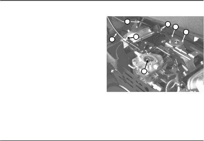
Throttle Control Adjustment (Fig. 1)
Before adjusting carburetor, make sure throttle control
is operating properly. 2
1
4
1. Loosen cable clamp screw securing cable to engine.
3
2. Move remote throttle control lever forward to FAST |
5 |
6 |
position.
3. Pull firmly on throttle cable until back of swivel contacts stop.
4. Tighten cable clamp screw.
7
Figure 1
1. Throttle casing clamp screw
2. Throttle cable
3. Swivel
4. Stop
5. Choke casing clamp screw
6. Choke cable
7. Choke butterfly
Choke Control Adjustment (Fig. 1)
1.Loosen cable clamp screw securing cable to engine.
2.Move remote choke control lever forward to CLOSED position.
3.Pull firmly on choke cable until choke butterfly is completely closed, then tighten cable clamp screw.
Adjustments |
Page 3 - 2 |
Greensmaster® 3100 |

Governor Adjustment (Before starting engine)
IMPORTANT: If carburetor has been removed or governor linkage disassembled, the governor lever, throttle restrictor and secondary governor spring must be adjusted before the engine is started.
Governor Lever Adjustment (Fig. 2)
All linkage must be installed to make adjustment. Loosen governor lever bolt and nut. Push on governor lever until throttle is wide open. DO NOT bend governor link. Hold lever in this position and rotate governor shaft counterclockwise as far as it will go. Hold lever and shaft in position and torque governor lever bolt and nut to 70 in-lb.
Throttle Restrictor Adjustment (Fig. 3)
Move throttle control lever to SLOW position. Hold governor lever so that throttle lever touches idle speed adjustment screw. Use tang bender (Briggs & Stratton Tool #19352) and bend throttle restrictor tang so throttle opening is limited to 1/4 in. travel when governor lever is released.
Secondary Spring Adjustments (Fig. 4)
With throttle control lever in SLOW position, install adjustment gauge (Brigss & Stratton Tool #19385) over end of governor lever as shown. Holding gauge in position, bend tab so that all slack is removed from secondary governor spring between its two anchor points. DO NOT STRETCH SPRING. Remove adjustment gauge.
Figure 2
Figure 3
Figure 4
Greensmaster® 3100 |
Page 3 - 3 |
Adjustments |
Carburetor and Speed Control Adjustment (Fig. 5, 6)
IMPORTANT: Before carburetor and speed control are adjusted, the throttle and choke controls must be adjusted properly.
WARNIN G
Engine must be running during adjustment of carburetor and speed control. To guard against possible personal injury, shift into neutral and engage parking brake. Keep hands, feet, face and other parts of the body away from the cutter blades and any rotating engine parts.
1.Start engine and let it run at half throttle for approximately five (5) minutes to warm up.
2.Move throttle control to SLOW position. Hold governor lever so throttle lever is in the idle position (against
idle stop screw) and turn idle stop screw in or out to get 1400 ± 50 RPM. Check speed with a tachometer.
3.Adjust idle mixture screw:
A.Turn idle mixture screw slowly clockwise (lean mixture) until engine speed just starts to decrease. Note position of screw.
B.Now turn idle mixture screw slowly counterclockwise (rich mixture) until engine speed just starts to decrease. Note position of screw.
C.Set the idle mixture screw half way between the rich and lean settings.
4.After idle mixture has been adjusted, hold governor lever so throttle lever is in idle position (against idle stop
screw) and adjust idle stop screw to bring engine speed to 1200 ± RPM.
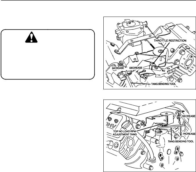
5.With governor control lever in governed idle position (no tension on high speed spring) bend governed idle
spring anchor tang to get a governed idle speed of 1400 ± RPM (Fig. 5).
6.Move throttle control to FAST position. Bend high speed spring anchor tang to bring engine speed to 2800 +50/–100 RPM (Fig. 6).
Figure 5
Figure 6
Adjustments |
Page 3 - 4 |
Greensmaster® 3100 |

Engine Removal and Installation
Removing the Engine
1.Disconnect the negative (–) and positive (+) battery cables from the battery.
2.Close the fuel shut-off valve and disconnect the fuel line.
WARNIN G
Gasoline is highly flammable. Use caution while handling it. Do not smoke cigarettes, cigars or pipes. Dispose of the gasoline in a safe place immediately after draining.
3.Remove the starter cable, throttle and choke cable and ground wire from engine.
4.Disconnect the wiring harness connector.
5.Loosen the two (2) set screws securing the pump hub onto the engine shaft. Remove the two (2) capscrews securing the pump to the pump mount. DO NOT disconnect the hydraulic hoses from the pump.
6.Support the engine and remove the engine mount bolts, nuts and washers to remove the engine.
Installing the Engine
1.Support the engine, align it with the engine mounts, and instal the pump hub over the engine shaft and key. Be sure that the key is properly positioned and aligned with the keyway.
2.Install the engine mount bolts, washers and nuts.
3.Mount the pump to the pump housing and tighten the set screws to secure the hub to the shaft.
4.Re-connect the fuel line, wire connectors and the cables to the engine and battery.
5.Make sure the crankcase is filled the correct oil. Open the fuel shut-off valve. Fill the fuel tank. Start the engine and check for proper operation.
Greensmaster® 3100 |
Page 3 - 5 |
Engine Removal and Installation |
Engine Removal and Installation |
Page 3 - 6 |
Greensmaster® 3100 |

Chapter 4
Hydraulic System
Table of Contents
SPECIFICATIONS . . . . . . . . . . . . . . . . . . . . . . . . . . 2 GENERAL INFORMATION . . . . . . . . . . . . . . . . . . . 3 Hydraulic Hoses . . . . . . . . . . . . . . . . . . . . . . . . . 3 Hydraulic Fitting Installation . . . . . . . . . . . . . . . . 3 HYDRAULIC FLOW DIAGRAMS . . . . . . . . . . . . . . . 5 Traction, No. 1 Position . . . . . . . . . . . . . . . . . . . . 5 Traction, No. 2 Position . . . . . . . . . . . . . . . . . . . . 6 Traction, Reverse Position . . . . . . . . . . . . . . . . . 7 Reel Drive, Mowing Operation . . . . . . . . . . . . . . 8 Reel Drive, Lower Cutting Units . . . . . . . . . . . . . 9 Reel Drive, Raising Cutting Units . . . . . . . . . . . 10 Power Steering, R.H. Turn . . . . . . . . . . . . . . . . . 11 HYDRAULIC SCHEMATIC. . . . . . . . . . . . . . . . . . . 12 SPECIAL TOOLS . . . . . . . . . . . . . . . . . . . . . . . . . . 13 TROUBLESHOOTING . . . . . . . . . . . . . . . . . . . . . . 16 Slow Groundspeed in All Traction Selections . . 17
Slow or No Ground Speed in No. 1
and Reverse, No. 2 Appears Normal . . . . . . . . 18 No Increase in Speed From No. 1 to No. 2 . . . . 19 One or More Cutting Units Slow
or No Reel Drive Action. . . . . . . . . . . . . . . . . . . 20 All Reels Slow or Will Not Turn . . . . . . . . . . . . . 21 Mow Pedal Won’t Stay Engaged -
Reels Slow Down or Stop . . . . . . . . . . . . . . . . . 22 Cutting Unit(s) Drop During Transport. . . . . . . . 23 Cutting Units Lift Too Slowly or Not At All . . . . . 24 Lift Pedal Binding . . . . . . . . . . . . . . . . . . . . . . . 25 Center (#1) Cutting Unit
Operates In Raised Position . . . . . . . . . . . . . . . 25 Center (#1) Cutting Unit Drops Before
Front Cutting Units or Drops Too Fast. . . . . . . . 25 Steering Loss, Steering Wander or Free Play. . 26 TESTING . . . . . . . . . . . . . . . . . . . . . . . . . . . . . . . . 27
Test Hook Up No. 1, Traction Pump
Flow and Traction Relief Setting . . . . . . . . . . . . 28
Test Hook Up No. 2, Traction
Motors Mechanical Drag, Valve
Bank Leakage,Traction Motors Efficiency . . . . . 28 Test Hook Up No. 3,
Reel Drive Pump Efficiency . . . . . . . . . . . . . . . . 32 Test Hook Up No. 4, Reel Drive Motor Flow,
Reel Drive Relief Setting, Reel Motor Efficiency 33 Test Hook Up No. 5, Steering Pump
Flow and Steering Pump Relief Setting. . . . . . . 35 ADJUSTMENTS . . . . . . . . . . . . . . . . . . . . . . . . . . . 36 Lift and Mow Pedal Height Adjustment . . . . . . . 36 Traction Pedal Adjustment. . . . . . . . . . . . . . . . . 37 Rear Camshaft Adjustment . . . . . . . . . . . . . . . . 38 REPAIRS . . . . . . . . . . . . . . . . . . . . . . . . . . . . . . . . 39 Reel Motor Removal and Installation. . . . . . . . . 39 Reel Motor Shaft Seal Replacement . . . . . . . . . 39 Reel Motor Repair . . . . . . . . . . . . . . . . . . . . . . . 40 Pump Removal and Installation. . . . . . . . . . . . . 42 Pump Repair . . . . . . . . . . . . . . . . . . . . . . . . . . . 43 Control Valve Removal and Installation. . . . . . . 44 Relief Valve Removal and Installation . . . . . . . . 45 Control Valve Spool Seal Replacement. . . . . . . 46 Control Valve Internal Seal Replacement . . . . . 47 Control Valve No. 1 Spool Detent Replacement 48 Control Valve No. 4 Spool Detent Replacement 49 Lift Cylinder Removal and Installation . . . . . . . . 50 Lift Cylinder Repair . . . . . . . . . . . . . . . . . . . . . . 52 Wheel Motor Removal and Installation . . . . . . . 54 Wheel Motor Repair. . . . . . . . . . . . . . . . . . . . . . 55 Steering Cylinder Removal and Installation. . . . 58 Steering Cylinder Repair . . . . . . . . . . . . . . . . . . 59 Steering Control Unit Removal and Installation. 60 Steering Control Unit Repair . . . . . . . . . . . . . . . 61
Greensmaster® 3100 |
Page 4 - 1 |
Table of Contents |

Specifications
Item |
Description |
__________________________________________________________________________________________ |
|
Hydraulic Pump |
External gear type |
|
5 section (Greensmaster 3100) |
|
4 section (Greensmaster 3050) |
Steering relief pressure (Greensmaster 3100) |
850 psi |
________________________________________________________________________________________________________________________________________________________ |
|
Wheel Motor (2) |
Orbit rotor type |
________________________________________________________________________________________________________________________________________________________ |
|
Reel Motor (3) |
External gear type |
________________________________________________________________________________________________________________________________________________________ |
|
Control Valve |
5 section spool type |
Main and No. 1 section port relief pressure |
2000 psi |
No. 2 and 3 section port relief pressure |
2000 psi |
No. 4 (traction) section port relief pressure |
1850 psi |
________________________________________________________________________________________________________________________________________________________ |
|
Power Steering Control |
Gerotor type steering control unit |
________________________________________________________________________________________________________________________________________________________ |
|
Hydraulic Oil |
See Operator's Manual |
________________________________________________________________________________________________________________________________________________________ |
|
Reservoir Capacity |
See Operator's Manual |
________________________________________________________________________________________________________________________________________________________ |
|
Oil filter |
Screw-on cartridge type, 10 micron |
|
|
Figure 1a (Greensmaster 3050)
1. Hydraulic reservoir |
2. Screen |
Specifications |
Page 4 - 2 Rev. D |
Greensmaster® 3100 |
General Information
Hydraulic Hoses
Hydraulic hoses are subject to extreme conditions such as, pressure differentials during operation and exposure to weather, sun, chemicals, very warm storage conditions or mishandling during operation or maintenance. These conditions can cause damage or premature deterioration. Some hoses, such as reel motor hoses, are more susceptible to these conditions than others. Inspect the hoses frequently for signs of deterioration or damage. To prevent possible problems it is recommended that hoses are replaced periodically, regardless of condition.
When replacing a hydraulic hose, be sure that the hose is straight (not twisted) before tightening the fittings. This can be done by observing the imprint on the hose. Use two wrenches; one to hold the hose straight and one to tighten the hose swivel nut onto the fitting.
WARNING
Before disconnecting or performing any work on the hydraulic system, all pressure in the system must be relieved by stopping the engine and lowering the cutting units to the ground.
Keep body and hands away from pin hole leaks or nozzles that eject hydraulic fluid under high pressure. Use paper or cardboard, not hands, to search for leaks. Hydraulic fluid escaping under pressure can have sufficient force to penetrate the skin and do serious damage. If fluid is injected into the skin, it must be surgically removed within a few hours by a doctor familiar with this type of injury or gangrene may result.
Hydraulic Fitting Installation
O-Ring Face Seal (Fig. 1, 2)
1.Make sure both threads and sealing surfaces are free of burrs, nicks, scratches, or any foreign material.
2.Make sure the O-ring is installed and properly seated in the groove. It is recommended that the O-ring be replaced any time the connection is opened.
3.Lubricate the O-ring with a light coating of oil.
4.Put the tube and nut squarely into position on the face seal end of the fitting and tighten the nut until finger tight.
5.Mark the nut and fitting body. Hold the body with a wrench. Use another wrench to tighten the nut to the correct flats from finger tight (F.F.F.T.). The markings on the nut and fitting body will verify that the connection has been tightened.
Size |
F.F.F.T. |
|||
4 |
(1/4 in. nominal hose or tubing) |
.75 |
± .25 |
|
6 |
(3/8 in.) |
.75 |
± .25 |
|
8 |
(1/2 in.) |
.75 |
± .25 |
|
10 |
(5/8 in.) |
1.00 |
± .25 |
|
12 |
(3/4 in.) |
.75 |
± .25 |
|
16 |
(1 in.) |
.75 |
± .25 |
|
Nut |
Body |
|
Sleeve
Seal
Figure 1
Mark Nut |
Final |
|
Position |
Initial |
|
and Body |
|
|
|
Position |
|
|
|
|
|
Extend Line |
|
Finger Tight |
After Proper Tightening |
|
Figure 2
Greensmaster® 3100 |
Page 4 - 3 |
General Information |
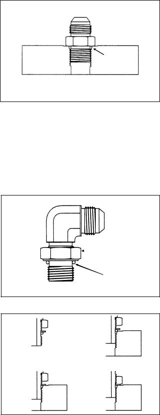
SAE Straight Thread O-Ring Port (Non-adjustable) (Fig. 3)
1.Make sure both threads and sealing surfaces are free of burrs, nicks, scratches, or any foreign material.
2.Always replace the O-ring seal when this type of fitting shows signs of leakage.
3.Lubricate the O-ring with a light coating of oil.
4.Install the fitting into the port and tighten it down full length until finger tight.
5.Tighten the fitting to the correct flats from finger tight (F.F.F.T.).
Size |
F.F.F.T. |
||
4 |
(1/4 in. nominal hose or tubing) |
1.00 ± .25 |
|
6 |
(3/8 in.) |
1.50 ± .25 |
|
8 |
(1/2 in.) |
1.50 ± .25 |
|
10 |
(5/8 in.) |
1.50 ± .25 |
|
12 |
(3/4 in.) |
1.50 ± .25 |
|
16 |
(1 in.) |
1.50 ± .25 |
|
SAE Straight Thread O-Ring Port (Adjustable) (Fig. 4, 5)
1.Make sure both threads and sealing surfaces are free of burrs, nicks, scratches, or any foreign material.
2.Always replace the O-ring seal when this type of fitting shows signs of leakage.
3.Lubricate the O-ring with a light coating of oil.
4.Turn back the jam nut as far as possible. Make sure the back up washer is not loose and is pushed up as far as possible (Step 1).
5.Install the fitting into the port and tighten finger tight until the washer contacts the face of the port (Step 2).
6.To put the fitting in the desired position, unscrew it by the required amount, but no more than one full turn (Step 3).
7.Hold the fitting in the desired position with a wrench and turn the jam nut with another wrench to the correct flats from finger tight (F.F.F.T.) (Step 4)
Size |
F.F.F.T. |
||
4 |
(1/4 in. nominal hose or tubing) |
1.00 ± .25 |
|
6 |
(3/8 in.) |
1.50 ± .25 |
|
8 |
(1/2 in.) |
1.50 ± .25 |
|
10 |
(5/8 in.) |
1.50 ± .25 |
|
12 |
(3/4 in.) |
1.50 ± .25 |
|
16 |
(1 in.) |
1.50 ± .25 |
|
O-Ring
Figure 3
 Lock Nut
 Back-Up Washer
O-Ring
Figure 4
Step 1 |
Step 3 |
Step 2 |
Step 4 |
Figure 5
General Information |
Page 4 - 4 |
Greensmaster® 3100 |
Hydraulic Flow Diagrams
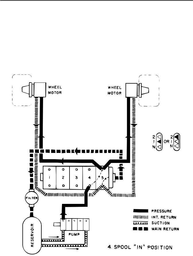
Traction, No. 1 Position
When engine is started, pump draws oil from reservoir through two suction lines. Oil from one section of pump passes through fitting in No. 4 spool valve into valve. Traction lever, when located in No. 1, positions spool so oil is directed to flow into the No. 5 metering valve
section. When the traction pedal is pushed forward oil flows out lines at rear of metering valve section to each motor to drive the motors. Low pressure oil returns to valve through valve and main return line, through filter to reservoir.
Greensmaster® 3100 |
Page 4 - 5 |
Hydraulic Flow Diagrams |
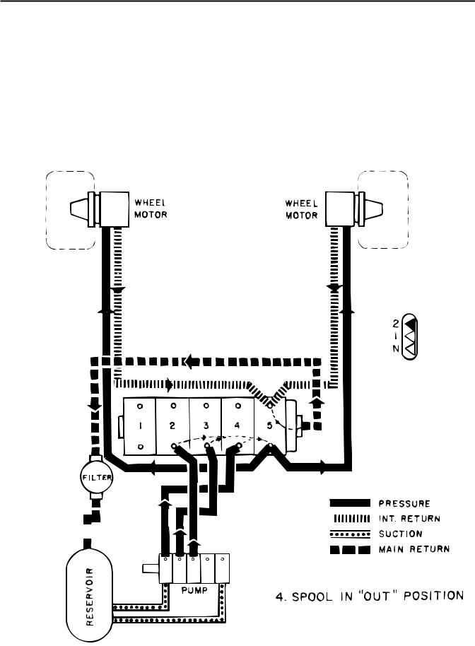
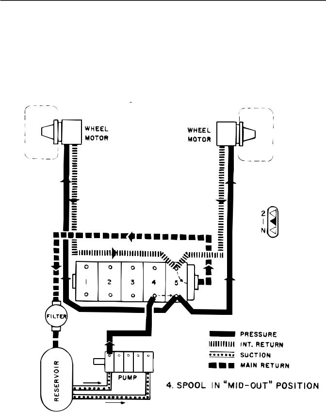
Traction, No. 2 Position
When the traction lever is positioned in No. 2, flow from one pump section passes through same lines as for No. 1 traction position. This flow is joined by additional flow
from two other pump sections. The additional flow increases the RPM of the wheel motors to increase ground speed.
|
|
|
|
|
|
Greensmaster® 3100 |
|
|
|
|
|
|
|
|
|
|
|
|
|
|
|
|
|
|
|
|
|
|
|
|
|
|
|
|
Hydraulic Flow Diagrams |
Page 4 - 6 |
|||||
Traction, Reverse Position
Traction lever is positioned in No. 1 or No. 2. When traction pedal is pushed rearward, flow from one pump section goes through No. 4 selector valve section into
No. 5 metering section and out the lines at the front of the valve to the traction motors, which drive the traction wheels, to operate in reverse.
Greensmaster® 3100 |
Page 4 - 7 |
Hydraulic Flow Diagrams |
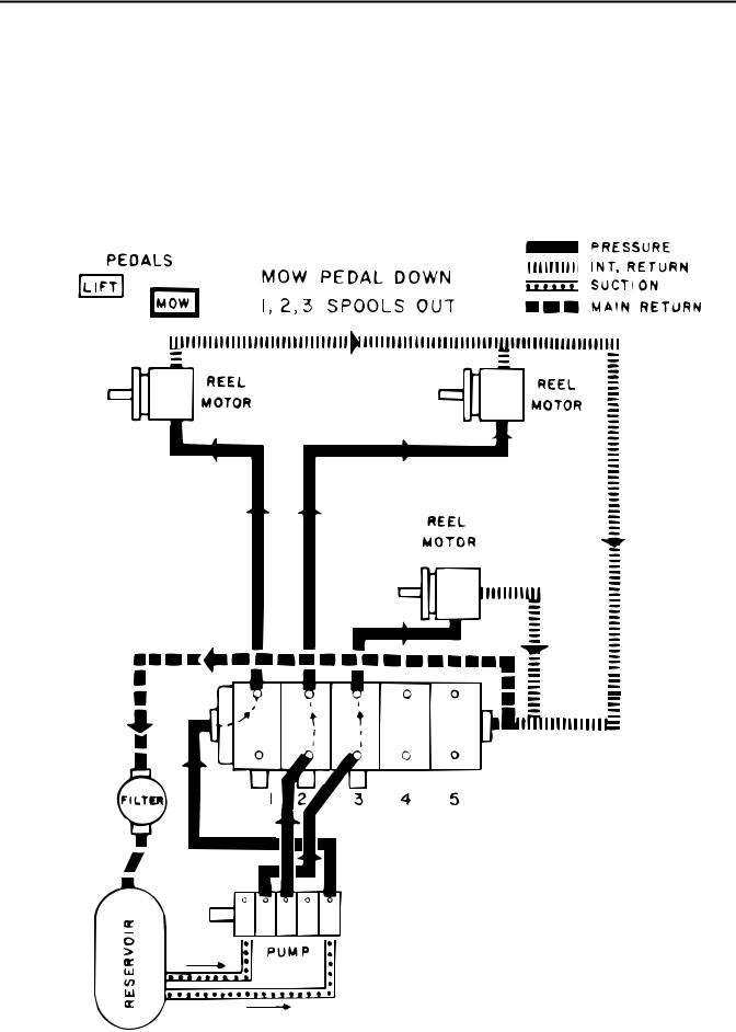
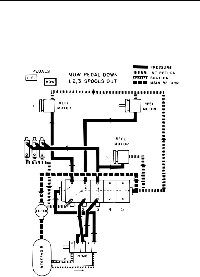
Reel Drive, Mowing Operation
The MOW pedal is depressed, which causes the No. 1, 2 and 3 spools to be positioned fully out of valve bank. This directs flow from one pump section to pass through left end cover and out line leading to left front cutting unit drive motor. Flow causes motor to turn, driving reel.
Flow from separate pump section passes through No. 2 valve section and out a line to right front cutting unit motor. Return oil from two front cutting units joins together and returns to right end of valve section, where
is passes into the main return line and flows back to reservoir.
Flow from another separate pump section passes through No. 3 spool section and out through a line to the rear cutting unit drive motor. Return oil from the motor passes through a line leading to the right hand end of the valve bank, where it also joins with the main return line back to the reservoir.
GR3100 WITH DANFOSS PUMP SHOWN.
MACHINES WITH PARKER PUMP USE
CENTER 3 PUMP SECTIONS FOR REEL
DRIVE CIRCUITS.
Hydraulic Flow Diagrams |
Page 4 - 8 Rev. E |
Greensmaster®3100 |
Reel Drive, Lower Cutting Units
The MOW pedal is depressed to start reel drive operation, flow from one pump section passes through No. 3 spool section and out three lines, each leading to a lift cylinder. This actuates the lift cylinders and lowers the cutting units. Oil is returned to a three-way fitting on the No. 1 spool section through lines on the top end of each
cylinder, where it passes through the valve section and returns to the reservoir through the main return line. When the cylinders complete their travel, oil flow from the No. 3 spool section is then directed to the rear cutting unit drive motor.
GR3100 WITH DANFOSS PUMP SHOWN.
MACHINES WITH PARKER PUMP USE
CENTER 3 PUMP SECTIONS FOR REEL DRIVE CIRCUITS.
Greensmaster®3100 |
Page 4 - 9 Rev. E |
Hydraulic Flow Diagrams |
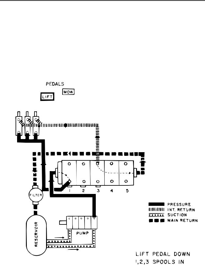
Reel Drive, Raising Cutting Units
When the LIFT pedal is depressed, No. 1, 2 and 3 spools are pushed inward. When spools pass neutral, cutting units stop operation. Holding pedal depressed keeps spools fully in. This directs flow from one pump section to pass through end cover and No. 1 spool valve, out
three lines leading to lift cylinders, causing cylinders to raise the cutting units. Oil forced out of cylinders travels through lines leading to No. 3 spool section, through the valve bank and back to reservoir through main return line.
GR3100 WITH DANFOSS PUMP SHOWN.
MACHINES WITH PARKER PUMP USE
FOURTH PUMP SECTION FOR LIFT.
Hydraulic Flow Diagrams |
Page 4 - 10 Rev. E |
Greensmaster®3100 |
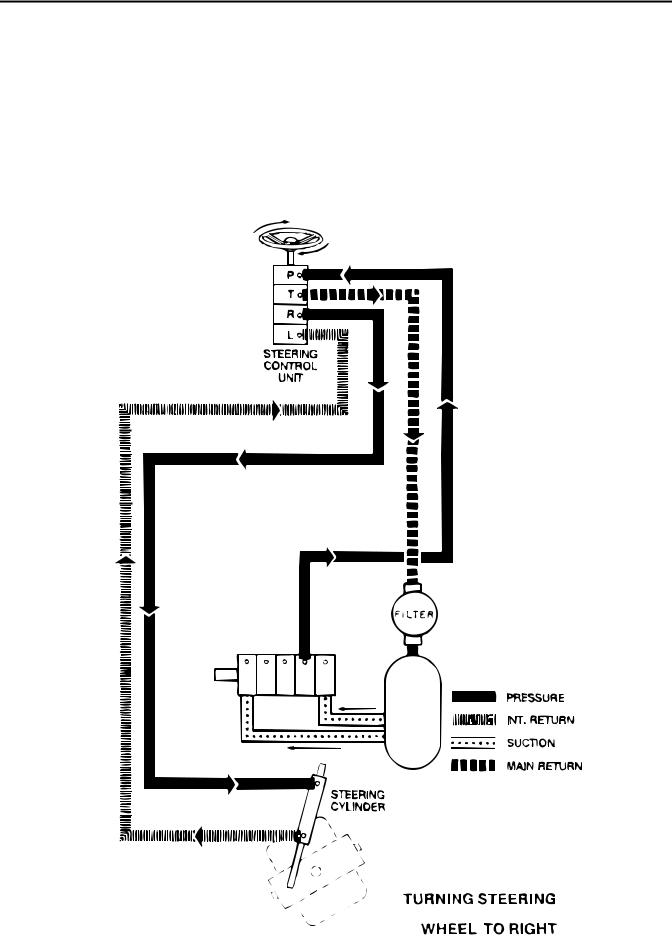
Power Steering, R.H. Turn (Greensmaster 3100)
Oil is supplied to port “P” of the steering control unit from the pump steering section. When the steering wheel is turned to the right, the control section within the steering valve shifts to direct oil supplied by the pump to the metering section of the steering valve. As the steering wheel turns, system oil is metered out port “R” to the steering cylinder. Oil displaced by the other end of the
steering cylinder returns to the steering valve through port “L” which directs it out port “T” back to reservoi r.
When the steering wheel stops turning, the control section within the steering valve shifts back to neutral allowing all oil from the pump to flow through the steering valve out port “T” back to reservoir. Oil in the rest of the steering circuit is then trapped.
GR3100 WITH DANFOSS PUMP SHOWN.
MACHINES WITH PARKER PUMP USE
LAST PUMP SECTION FOR STEERING CIRCUIT.
Greensmaster®3100 |
Page 4 - 11 Rev. E |
Hydraulic Flow Diagrams |
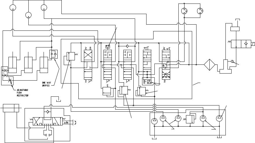
Schematics Hydraulic
E .Rev 12 – 4 Page
3100 Greensmaster
|
REEL MOTORS |
|
|
|
.43 CU. IN/REV. |
WHEEL DRIVE MOTORS |
|
|
(7 CU. CM/REV.) |
10.3 CU. IN/REV. |
|
|
|
(169 CU. CM/REV) |
|
LH |
CENTER |
|
|
|
|
LH |
RH |
|
|
|
|
|
RH |
|
TANK BREATHER |
|
|
40 MICRON |
|
|
|
|
|
|
SAFETY |
|
AUXILIARY |
|
INTERLOCK |
|
|
|
|
HYDRAULIC |
|
|
SWITCH |
|
|
|
|
TANK |
|
|
|
2ND |
|
NORMALLY OPEN |
|
|
FWD |
SOLENOID VALVE |
|
|
|
|
OIL FILTER |
|
|
|
|
|
|
|
|
|
|
10 MICRON |
LH |
RH |
1ST |
N |
|
|
LEVEL |
|||
|
|
CENTER |
|
SENSOR |
|
|
|
|
|
|
|
N |
|
|
|
|
|
REV |
HYDRAULIC |
|
|
|
|
|
|
|
|
|
TANK |
|
LIFT CYLINDERS |
|
|
|
|
SAFETY INTERLOCK |
VALVE BANK |
|
|
|
|
|
|
|
|
|
|||
|
|
|
|
|
|
SWITCH |
|
|
|
|
|
|
2000 PSI |
2000 PSI |
|
1850 PSI |
|
|
|
|
|
|
(141 KG/SQ CM) |
|
(130 KG/SQ CM) |
|
|
|
|
|
|
|
(141 KG/SQ CM) |
|
|
|
|
||
|
|
|
|
|
|
|
|
|
|
STEERING CYLINDER |
|
|
|
|
|
|
|
.33 IN3/REV |
|
|
|
|
|
|
|
|
|
|
(5.4 CU CM/REV) |
L |
R |
P |
T |
|
|
|
|
|
|
|
|
|
|
|
|
|
|
||
|
|
|
|
|
2000 PSI |
|
|
|
|
|
|
|
|
|
(141 KG/SQ CM) |
|
|
|
|
|
|
|
|
|
.58 IN3/REV |
3 |
850 PSI |
3 |
PUMP (DANFOSS) |
|
|
|
|
|
.33 IN /REV |
.18 IN /REV |
2850 RPM MAX |
||
|
|
|
|
STEERING CONTROL VALVE |
(9.5 CU CM/REV) |
(5.4 CU CM/REV) |
(60 KG/SQ CM) |
(2.9 CU CM/REV) |
|
|
|
|
|
4.5 CU. IN/REV. |
|
|
|
|
|
|
|
|
|
(75 CU. CM/REV) |
|
|
|
|
|
Serial 2WD 3100 (Greensmaster |
Schematic Hydraulic |
230000000) Below Number |
|
Loading...