


User’s Guide
12 Stations
Modules
Odd/Even Days
Run Time
Outdoor Model
|
ON |
MANUAL |
NEXT |
START |
|
PROGRAMS
A B C
OFF
Indoor Model

Table of Contents |
|
Introduction and Set Up |
|
■ GreenKeeper 212 Components...................... |
2-5 |
■ Sprinkler System Basics .................................... |
6 |
■ Watering Program Basics .................................. |
7 |
■ Watering Program Details .............................. |
8-9 |
■ Planning Your Watering Schedule................... |
10 |
■ Filling Out the Watering Schedule Form..... |
10-11 |
Watering Schedule Form .............................. |
12 |
■ Programming Before Installation ..................... |
13 |
■ Installing the Battery ........................................ |
13 |
■ Selecting Optional Features ............................ |
14 |
24-Hour Clock Mode ..................................... |
14 |
15-Second Run Delay .................................. |
14 |
Odd/Even Watering Days.............................. |
14 |
■ About the Controller Memory........................... |
14 |
■ Resetting the Controller Memory ..................... |
15 |
To Reset the Permanent Memory ................. |
15 |
To Clear the Memory ................................... |
15 |
Programming the Controller |
|
■ Setting the Current Time and Day or Date ...... |
16 |
■ Setting the Watering Day Schedule............ |
17-19 |
Setting a Calendar Schedule ........................ |
17 |
Setting an Interval Schedule ......................... |
18 |
Setting an Odd or Even Schedule................. |
19 |
Turning Off a Program ................................. |
19 |
■ Setting Program Start Times ........................... |
20 |
■ Setting Station Run Times ............................... |
21 |
Controller Installation
■ Indoor Model Installation .............................. |
22 |
|
|
|
Connecting the Valves .................................. |
23 |
|
|
|
Connecting a Pump Start Relay.................... |
24 |
|
|
|
Connecting the Transformer ......................... |
24 |
|
|
|
■ Outdoor Model Installation ........................... |
25 |
|
|
|
Preparing the Cabinet for Installation............ |
25 |
|
|
|
Installing the Cabinet..................................... |
26 |
|
|
|
Connecting the Valves .................................. |
27 |
|
|
|
Connecting a Pump Start Relay.................... |
28 |
|
|
|
Connecting the Power Source ................ |
28–29 |
|
|
|
■ Connecting a Toro Rain Switch ....................... |
29 |
|
|
|
Controller Operation |
|
|
|
|
■ Automatic Operation ..................................... |
30 |
|
|
|
■ Manual Operation .......................................... |
31 |
|
|
|
Starting Programs or Stations Manually........ |
31 |
|
|
|
Watering Control Features ............................ |
32 |
|
|
|
|
To Pause Watering ..................................... |
32 |
|
|
|
To Resume Watering .................................. |
32 |
|
|
|
To Cancel Watering .................................... |
32 |
|
|
|
To Skip Zones............................................. |
32 |
|
|
|
To Adjust the Station Run TIme.................. |
33 |
|
|
■ Turning Off the GreenKeeper 212 ................... |
33 |
|
|
|
■ Using the Rain Delay Feature.......................... |
33 |
|
|
|
■ Using the Season Adjust Feature .................... |
34 |
|
|
|
Service and Specifications |
|
|
|
|
■ Replacing the Fuse.......................................... |
35 |
|
|
|
■ Adding a Station Module.................................. |
36 |
|
|
|
■ Troubleshooting ............................................... |
36 |
|
|
|
■ Specifications................................................... |
37 |
|
|
|
■ Warranty .......................................................... |
38 |
|
1 |
|
■ Electromagnetic Compatibility ......................... |
38 |
|||
GreenKeeper 212 Introduction
and Set Up
Controller Components
1
2
3 


BATTERY 
2

GreenKeeper 212 Components
The following are brief descriptions of the controller components and display elements. Each of these items will be explained in further detail within the appropriate programming, operating and installation sections of this guide.
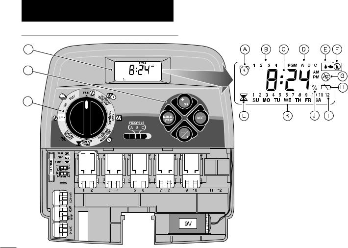
1 - LCD Display
A - “Start Time” symbol – Alarm clock is displayed when setting the program start times.
B - Program start time identification numbers 1–4.
C - Main display of various time values and prompts.
D - Program A, B and C identifiers.
E - “Watering On” symbol – Water droplet indicates a watering station is running. Droplet flashes if watering is paused.
F - “Watering Off” symbol – Water droplet with slash indicates all watering activity is Off.
G - “Power Off” symbol – Displayed when main power is disconnected and controller is on battery power only.
H - “Low Battery Voltage” symbol – Indicates low battery voltage (when main power is disconnected).
I - Watering Station identification numbers.
J - “Percent” symbol – Indicates the Season Adjust feature is in use.
K - Day of the week identifiers.
L - “Run Time” symbol – Hourglass is displayed when setting the watering station run times.
2 - Control Buttons
+/ON button – Increases the time display, scrolls forward through the program information and selects watering days.
–/OFF button – Decreases the time display, scrolls backward through the program information and removes watering days.
NEXT button – Advances to the next portion of program information. Resumes watering if paused. Advances through stations manually when watering.
MANUAL START button – Selects and starts manual watering operations.
3 - Control Dial – Selects all controller programming and operation controls (except Manual Start).
Control Dial Positions
RUN  – The normal dial position for all automatic and manual operations.
CURRENT TIME/DAY
 – Enables the clock time and day to be set.
WATERING DAYS  – Enables the watering day schedules to be set and reviewed.
PROGRAM START TIME – Enables the program start times to be set and reviewed.
STATION TIMES  – Enables the station run time to be set and reviewed.
(continued)
3

Controller Components
3 - Control Dial Positions (continued)
SEASON ADJUST  – Enables the run time of all zones in a program to be simultaneously increased or decreased in 10% increments.
OFF  – Shuts off and prevents all automatic and manual watering activity.
RAIN DELAY  – Enables all watering operations to be delayed from 1 to 7 days.
4 - Program Select Switch – Three-position slide switch used to select watering program A, B or C during the programming procedures and manual operation.
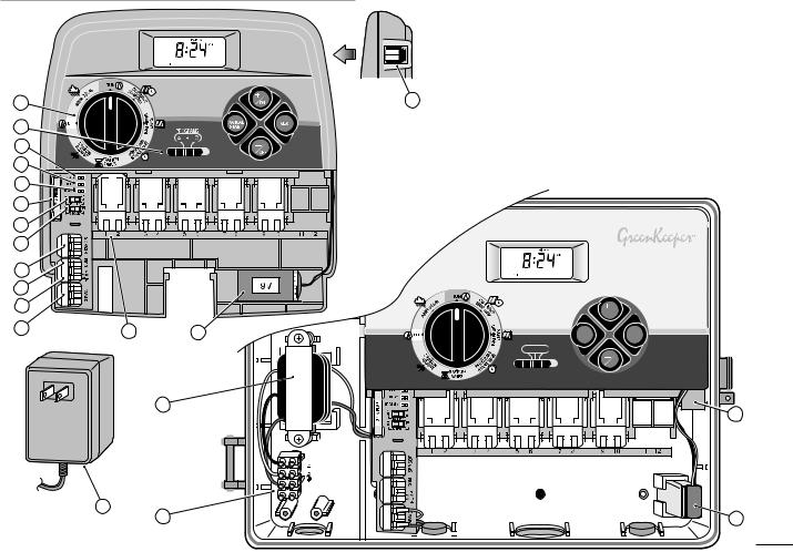
5 - 12 or 24-Hour Clock Selector Jumper – Removing this jumper selects 24-hour (military time) clock mode. Jumper installed selects 12-hour clock mode.
6 - Run Delay Selector Jumper– Removing this jumper selects a 15-second delay period before a station begins watering. Jumper installed provides a 2-second delay.
7 - Odd/Even Day Schedule Selector Jumper –
Removing this jumper enables an Odd or Even watering day schedule to be selected.
8 - Fuse – Domestic - 0.75A, 3AG (shown throughout manual). Export - 0.63A, (not shown).
9 - Battery Charger Switch – Controls the battery charging circuit. Switch positions provided for Alkaline (ALK) and rechargeable (RCHG) batteries.
10 - Rain Sensor Control Switch – Controls the sensor
4input circuit. Switch positions provided for sensor circuit On and Off.
11 - Sensor Connection Terminals – Snap-in connectors for connection of an (optional) Toro Rain Switch.
12 - Valve Common Connection Terminal – Snap-in wire connector for the valve common wire.
13 - Pump/Master Valve Connection Terminal –
Snap-in wire connector for a pump start relay or master valve.
14 - Transformer Connection Terminals – Snap-in connectors for the plug-in transformer wires.
15 - Plug-In Station Control Module – Each control module provides snap-in connectors for two station control valve power wires. Up to six modules can be installed.
16 - 9-Volt Battery – The battery maintains the controller memory if the transformer power is disconnected. Either an Alkaline or rechargeable Ni-MH battery can be installed.
17 - Power Supply – A Plug-in transformer supplies 24 V a.c. power to the indoor controller models. (Domestic transformer version shown.)
18 - Remote Control Receiver Jack – Modular jack provided for connection of the optional Toro Remote Control receiver cable.
(Refer to the instructions provided with the remote control device for installation and operation details.)
19 - Transformer – A built-in transformer supplies 24 V a.c. power to the outdoor controller models.
20 - Terminal Block – Input power wire connection terminals for outdoor controller models.
Controller Components
3 |
|
|
18 |
|
|
|
4 |
|
|
|
|
|
|
5 |
|
|
|
|
|
|
6 |
|
|
|
|
|
|
7 |
|
|
|
|
|
|
8 |
BATTERY |
|
|
|
|
|
9 |
|
|
|
|
|
|
10 |
|
|
|
|
|
|
11 |
|
|
|
|
|
|
12 |
|
|
|
|
|
|
13 |
|
|
|
|
|
ON |
|
|
|
|
|
|
|
14 |
15 |
16 |
|
|
MANUAL |
NEXT |
|
|
|
||||
|
|
|
|
|
START |
|
|
|
|
PROGRAMS |
|
||
|
|
|
A |
B |
C |
|
|
|
|
|
|
|
OFF |
19 |
18
BATTERY 
17
20 |
16 |
5
Sprinkler System Basics
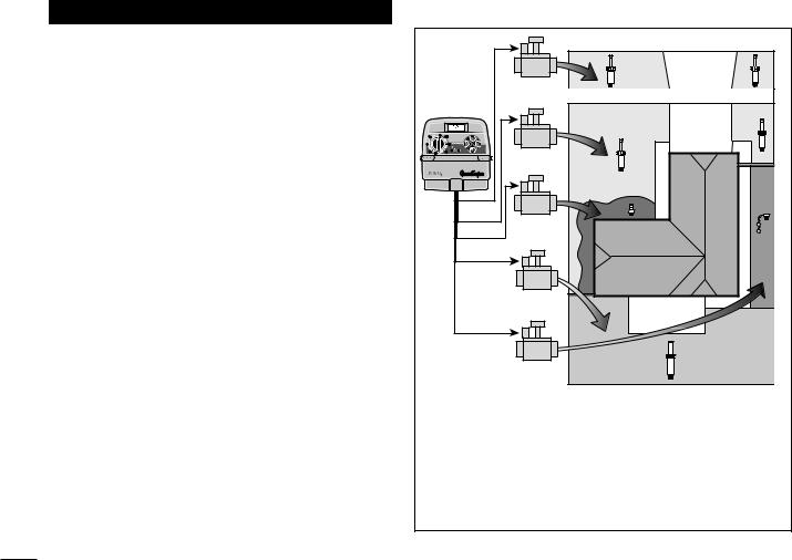
The three main components of every automatic sprinkler system are the controller, station control valves and sprinklers.
The controller is the brain of the system, telling the control valves when and how long to supply water to the sprinklers. The sprinklers direct and control the water applied to the lawn and plants.
Each valve controls a specific group of sprinklers called a watering station. The stations are generally laid out and installed according to the type of plant material to be watered, the location of the plant within the landscape and the maximum amount of water which can be supplied. Each valve is connected to a numbered terminal within the controller, identifying it as Station 1, Station 2, etc.
The controller operates the valves in order, one at a time. In other words, one station would water completely before another station would turn on. This is called a watering cycle. The information stored in the controller memory which determines when and how long the stations will water is called a program.
The next section of this guide is very important. It explains what a program is and how the GreenKeeper 212 controls the operation of the sprinkler system.
Valve 1
Controller
Valve 2
Valve 3
House
Valve 4
Valve 5
Valve 1 - Station 1 - Parkway Lawn - Fixed Spray
Valve 2 - Station 2 - Front Lawn - Fixed Spray
Valve 3 - Station 3 - Front Shrubs - Flood Bubbler
Valve 4 - Station 4 - Back Lawn - Geared Rotor
Valve 5 - Station 5 - Garden - Drip
6
Watering Program Basics
A watering program requires three basic instructions to operate automatically:
•What days to water –called watering days
•When to water – called a program start time
•How long to water – called station run time
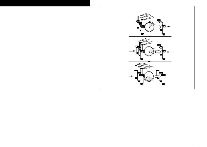
The following example illustrates how a typical watering program could be set for the sprinkler system shown on the previous page.
Example: The program start time is set for 5:00 AM. Lawn stations 1 and 2 each have a run time of 10 minutes and lawn station 4 is set to run for 20 minutes. Note that stations 3 and 5 water shrubs and flowers and have been excluded from this program. (These stations will be set to operate on separate programs).
As shown in the watering program diagram, at 5:00 AM the controller starts the program watering cycle. Station 1 sprinklers run for 10 minutes and shut off. Station 2 sprinklers turn on, run for 10 minutes and shut off. The controller skips station 3 and turns on station 4, which runs for 20 minutes and shuts off. Station 5 is skipped and the watering cycle ends at 5:40 AM.
As you can see from this example, only one program start time was needed to operate three different stations.
Because of variations in plant watering needs, the GreenKeeper 212 provides three separate programs. The programs, called A, B and C, are completely independent of one another – like having three timers in one housing.
Watering Program Diagram
Program
Starts - 5:00 AM
Station 1
|
12 |
9 |
3 |
|
6 |
|
12 |
|
|
9 |
|
3 |
|
Station 2 |
6 |
|
|
|
12 |
|
Program |
9 |
|
3 |
|
Station 4 |
6 |
|
Ends- 5:40 AM |
Using more than one program for example, would enable lawn zones to be watered every day on program A, shrub zones to run on on Monday, Wednesday and Friday on program B and drip irrigation to soak the flower beds every three days on program C.
Although the GreenKeeper 212 offers the multiple program feature, you may want to have all zones on one program if it meets your needs. The other programs can remain turned off until you need to use them.
7
Watering Program Details
This section covers in detail each of the three parts of a watering program – watering days, program start times and station run times.
Selecting Watering Days
The GreenKeeper 212 provides four options for scheduling watering days: Calendar, Interval, Odd or Even and Off.
Calendar Schedule
A Calendar schedule enables you to select specific days of the week to water, for example, Monday, Wednesday and Friday. This is a seven-day schedule which starts on Sunday and ends on Saturday.
This illustration shows how a Calendar schedule would be displayed when the control dial is in the
WATERING DAYS  position.
In this example, program A has watering days set for MO (Monday), WE (Wednesday) and FR (Friday).
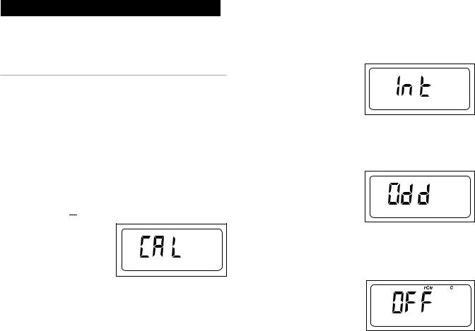
Interval Schedule
PGM A |
SU MO TU WE TH FR SA |
|
An Interval schedule enables you to set watering days |
|
without regard to the actual days of the week. For exam- |
|
ple, if you want to water every third day, you would |
|
select a 3-day Interval. Interval schedules range from |
|
1-day (watering every day) to 7-day (watering every sev- |
8 |
enth day). Once you have selected an Interval schedule, |
|
you can choose which day of the week will be the first day of the Interval. The number of days in the Interval determines the available start days. For example, if you have selected a 3-day Interval and today is Sunday, you may choose to start the Interval today, Monday or Tuesday.
This illustration shows how an Interval schedule would be displayed. In this example, program B has a 3-day Interval schedule which will start on Monday.
|
|
|
|
PGM |
A |
B |
C |
|
1 |
2 |
3 |
4 |
5 |
|
6 |
7 |
8 |
SU MO TU WE TH FR SA |
|
|||||||
Odd/Even Schedule
The Odd/Even schedule enables you to select odd or even numbered days of the month as watering days.
This illustration shows how |
PGM A |
an Odd day schedule |
|
would be displayed. |
|
Program Off |
|
Selecting OFF suspends the operation of the program when it is not needed. Turning the program off does not alter or erase the watering day schedule of the program, it simply places the program on hold until it is needed.
This illustration shows how a program would be displayed if its watering day schedule is turned off. In this example, program C is off.
Selecting Program Start Times
A program start time is the time of day you select to begin an automatic program watering cycle.
It is important to remember that a program only requires one start time to operate automatically.
When a program starts, each station assigned to the program will water in numerical order, one at a time for its set run time.
Sometimes it is necessary to run a watering program more than one time per day. For example, when growing a new lawn. The GreenKeeper 212 enables each program to have up to four separate start times per day.
Program start times are numbered 1 through 4. These numbers are shown at the top left of the display next to the start time symbol 
 when the control dial is in the PROGRAM START TIME
 position and indicate how many start times are currently set for the program.
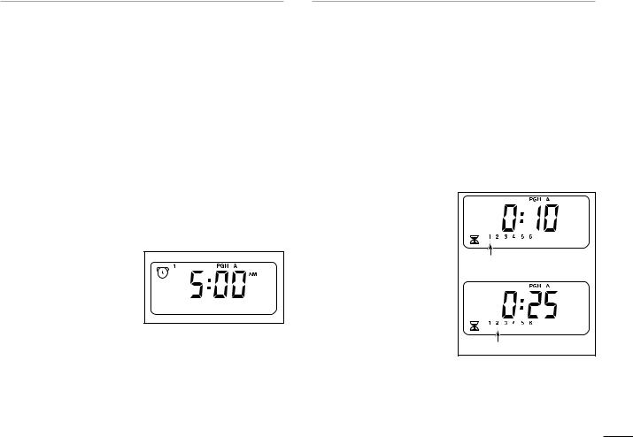
This illustration shows how a program start time is displayed. In this example, program A has one start time (start time number 1) set for 5:00 AM.
Setting the Station Run Time
A station run time is the length of time the station (controlled by the valve) will water during the program watering cycle. The run time for each station can be set from Off (no run time) to 4 hours, in one-minute increments.
A station is assigned to a program when it is given a run time. If the run time for a station is turned Off in a program, it will not operate during the program watering cycle. This is how the GreenKeeper 212 enables you to assign stations to different programs.
All stations assigned to the program are shown on the lower portion of the display when the control dial is in the
STATION TIMES  position.
This illustration shows how a station run time is displayed for a program. In this example, zones 1–6 are assigned to program A. Station 1 has a 10-minute run time and station 2 is set to run for 25 minutes.
The station run time being displayed is identified by the flashing station number.
Flashing |
Flashing |
9
Planning Your Watering Schedule
It is always helpful to plan your watering schedule on paper before beginning the programming steps. You will have a record of your watering schedule and station locations which can be kept with your GreenKeeper 212 after it is installed. If you have an indoor model controller, a watering schedule form is provided on page 12 for you to fill out then remove to keep with the controller. This form is duplicated on a decal located on the inside cover of the outdoor model.
Guidelines for Watering
There are several factors to be considered when deciding when and how long to water. For example, the soil type (i.e., clay, loam, etc.), the part of the landscape being watered, climate conditions and the type of sprinklers being used. Because of these variables, we cannot provide an exact schedule to follow, but here are some general watering guidelines to help you get started.
•Water early in the morning, one to two hours before sunrise. You will have the best water pressure at this time and the water can soak into the plant root zone while evaporation is minimal. Watering during mid-day or in the evening may cause plant damage or mildew.
•Watch for signs of underor over-watering and make program adjustments immediately.
Filling Out the Watering Schedule Form
When filling out this form, use a pencil so changes can be easily made. After installing the indoor model controller,
10 remove the form and store it in the pocket formed
between the mounting bracket and the back of the controller housing.
Refer to the example form shown on the opposite page and fill out your form in a similar manner with the following information:
•Location - Identify the location of each watering station and the type of plant being watered.
Note: Enter the following information for each program. If the program is not needed, leave its information column blank.
•Watering Day Schedule - For a Calendar schedule, indicate which day(s) of the week watering is desired. For an Interval schedule indicate the desired Interval number. For Odd or Even days, simply mark the appropriate box.
•Station Run Time - Indicate the amount of run time
(1 minute to 4 hours) for each station. Write “Off” for any station which you do not want to operate in the program.
•Program Start Times - Indicate the time of day to start the program. Each program can have 1 to 4 start times per watering day.
Note: The GreenKeeper will run only one watering cycle at a time. Therefore, when using multiple start times within a program or when using multiple programs, make sure that each watering cycle will be able to run completely before the next watering cycle is scheduled to start. A program start time that occurs while a watering cycle is in progress will be delayed until the current watering cycle is finished.

(Example) |
11 |
 Loading...