


 Loading...
Toro 74901, 74901CP, 74902TE, 74903, 74903CP Service Manual
...
LCE Products
Toro Z Master G3
3000/5000/6000 Series
Service Manual

ABOUT THIS MANUAL
This service manual was written expressly for Toro service technicians. The Toro Company has made every effort to make the information in this manual complete and correct.
Basic shop safely knowledge and mechanical/electrical skills are assumed. The Table of Contents lists the systems and the related topics covered in this manual.
The following service materials are available in addition to this service manual:
Hydrostatic Transmissions: |
Parker UHT Series HB Hydrostatic Transmission Service Manual (HY13-1512-M2/US) |
Wheel Motors: |
Parker/Ross Wheel Motor Service Manual (HY13-1512-006-M1/US 3/07) |
Engine: |
Engine service manuals (available through Kohler and Kawasaki) |
Hydraulic Troubleshooting: |
Interactive Hydraulic Systems Troubleshooting DVD - Toro Part #492-4777 |
Electrical Troubleshooting: |
Interactive Electrical Troubleshooting DVD - Toro Part #492-9193 |
The Z Master G3, 3000, 5000, and 6000, model years 2009 to 2012, are covered in this manual.
The hydrostatic drive system is precision machinery. Maintain strict cleanliness control during all stages of service and repair. Cover or cap all hose ends and fittings whenever they are exposed. Even a small amount of dirt or other contamination can severely damage the system.
We are hopeful that you will find this manual a valuable addition to your service shop. If you have any questions or comments regarding this manual, please contact us at the following address:
The Toro Company
RLC Service Training Department
8111 Lyndale Avenue South
Bloomington, MN 55420
The Toro Company reserves the right to change product specifications or this manual without notice.
Copyright© All Rights Reserved
©2012 The Toro Company

ABOUT THIS MANUAL
THIS PAGE INTENTIONALLY LEFT BLANK.

TABLE OF CONTENTS
1 - Safety Information
General Information 1-1 Think Safety First 1-1
2 - Specifications
Torque Specifications 2-1 Standard Torque for Dry, Zinc Plated & Steel Fasteners (Inch Series) 2-2 Standard Torque for Dry, Zinc & Steel Fasteners (Metric Fasteners) 2-3 Other Torque Specifications 2-4 Equivalents & Conversions 2-5
Decimal & Millimeter Equivalents 2-5 U.S. to Metric Conversions 2-6 G3 3000/5000/6000 Series Specifications 2-7 G3 3000/5000/6000 Series Specifications cont. 2-8 G3 3000/5000/6000 Series Specifications cont. 2-9 Dimensions 2-10 Commercial 3000 Series 2-10 G3/Professional 5000 Series 2-10 Dimensions 2-11 G3/Professional 6000 Series 2-11 Dimensions 2-12 G3/Professional 6000 Series cont. 2-12
3 - Chassis
Caster Fork Assembly Replacement 3-1 Caster Fork Assembly Removal 3-1 Caster Bearing Replacement 3-2 Caster Fork Assembly Installation 3-4 Front Wheel Bearing Replacement 3-5 Front Wheel Bearing Removal 3-5 Front Wheel Bearing Installation 3-7 Fuel Tank Replacement 3-9 Fuel Tank Removal 3-9 Fuel Tank Installation 3-12 Throttle Control Assembly Replacement (Kohler EFI Engine) 3-14 Throttle Control Assembly Removal 3-14 Throttle Control Assembly Installation 3-16 Park Brake Handle Assembly Replacement (2012 & Later) 3-18 Park Brake Handle Removal (2012 & Later) 3-18 Park Brake Handle Installation (2012 & Later) 3-20 Park Brake Cable Replacement (2011 & Prior) 3-21 Left Park Brake Cable Removal (2011 & Prior) 3-21 Left Park Brake Cable Installation (2011 & Prior) 3-24 Right Park Brake Cable Removal (2011 & Prior) 3-27 Right Park Brake Cable Installation (2011 & Prior) 3-29 Adjusting the Parking Brake 3-32 Park Brake Cable Replacement (2012 & Later) 3-34 Left Park Brake Cable Removal (2012 & Later) 3-34 Left Park Brake Cable Installation (2012 & Later) 3-37 Right Park Brake Cable Removal (2012 & Later) 3-41 Right Park Brake Cable Installation (2012 & Later) 3-44
Toro Z Master G3 3000/5000/6000 Series Service Manual |
i |

TABLE OF CONTENTS
3 - Chassis cont.
Brake Caliper Replacement 3-47 Brake Caliper Removal 3-47 Brake Caliper Installation 3-49 Motion Control Damper Replacement 3-51 Motion Control Damper Removal 3-51 Motion Control Damper Installation 3-52 Adjusting the Motion Control Damper 3-52 Adjusting the Motion Control Neutral Lock Pivot 3-53 Adjusting the Control Handle Position 3-53 Motion Control Assembly Replacement 3-54 Motion Control Assembly Removal 3-54 Motion Control Assembly Installation 3-58
4 - Engine
Engine Replacement 4-1
Engine Removal 4-1
Engine Installation 4-7
5 - Hydraulic System
Hydrostatic Pump Removal 5-1 G3 UHT Transmission Replacement (2009 through 2011 models) 5-1 G3 UHT Transmission Removal (2009 - 2011 models) 5-1 G3 UHT Transmission Installation (2009 - 2011 models) 5-9 Burnishing the Brake 5-20 UHT Transmission Replacement (2012 & later models) 5-23 UHT Transmission Removal (2012 & later models) 5-23 UHT Transmission Installation (2012 & later models) 5-28 Wheel Hub Slotted Nut Installation 5-32 Adjusting the Motion Control Linkage (Neutral Adjustment) 5-34 Checking the Hydraulic Oil 5-36 Flow Test Instructions 5-37 Hydraulic Pump Drive Belt Replacement 5-40 Using the Drive Wheel Release Valves 5-41
6 - Mower Decks
Mower Belt Replacement 6-1 Mower Belt Removal 6-1 Mower Belt Installation 6-2 Mower Deck Replacement 6-3 Mower Deck Removal 6-3 Mower Deck Installation 6-6 Extension Spring Adjustment (2010 - 2012 Models) 6-6 Mower Spindle Replacement 6-7 Mower Spindle Removal (2009 Model G3 Series Units) 6-7 Mower Spindle Installation (2009 Model G3 Series Units) 6-8 Mower Spindle Disassembly (2009 Model G3 Series Units) 6-9 Mower Spindle Assembly (2009 Model G3 Series Units) 6-12 Mower Spindle Replacement (2010 & Later Model G3, 3000/5000/6000 Series Units) 6-16 Mower Spindle Removal (2010 & Later Model G3, 3000/5000/6000 Series Units) 6-16 Mower Spindle Installation (2010 & Later Model G3, 3000/5000/6000 Series Units) 6-17
ii |
Toro Z Master G3 3000/5000/6000 Series Service Manual |

TABLE OF CONTENTS
6 - Mower Decks cont.
Mower Spindle Disassembly (2010 & Later Model G3, 3000/5000/6000 Series Units) 6-18 Mower Spindle Assembly (2010 & Later Model G3, 3000/5000/6000 Series Units) 6-20 Leveling the Mower Deck 6-23 Deck Leveling 6-23 Servicing the Cutting Blades 6-27 Before Inspecting or Servicing the Blades 6-27 Inspecting the Blades 6-28 Checking for Bent Blades 6-28 Removing the Blades 6-29 Sharpening the Blades 6-30 Installing the Blades 6-30 Electric PTO Clutch Replacement 6-31 Electric PTO Clutch Removal 6-31 Electric PTO Clutch Installation 6-32 Using the Clutch Shim 6-33 Removing the Clutch Shim 6-33 Safety Check 6-35
7 - Electrical
General 7-1 Relay 7-1 Purpose 7-1 Location 7-1 How It Works 7-1 Testing 7-2 PTO Switch 7-3 Purpose 7-3 Location 7-3 How It Works 7-3 Testing 7-3 Ignition Switch 7-5 Purpose 7-5 Location 7-5 How It Works 7-5 Testing 7-5 Park Brake Switch 7-6 Purpose 7-6 Location 7-6 How It Works 7-6 Testing 7-6 Seat Switch 7-7 Purpose 7-7 Location 7-7 How It Works 7-7 Testing 7-7 Neutral Safety Switch 7-8 Purpose 7-8 Location 7-8 How It Works 7-8 Testing 7-8
Toro Z Master G3 3000/5000/6000 Series Service Manual |
iii |

TABLE OF CONTENTS
7 - Electrical cont.
TVS Diode 7-9 Purpose 7-9 Location 7-9 How It Works 7-9 Testing 7-9
Fuel Sender 7-10 Purpose 7-10 Location 7-10 How It Works 7-10 Testing 7-10
Fuel/Hour Meter 7-11 Purpose 7-11 Location 7-11 How It Works 7-11 Testing 7-11
Electric PTO Clutch 7-12 Purpose 7-12 Location 7-12 How It Works 7-12 Testing 7-12 Coil Resistance Measurement 7-12 Measuring Clutch Current Draw 7-13
iv |
Toro Z Master G3 3000/5000/6000 Series Service Manual |

SAFETY INFORMATION
General Information |
|
|
|
|
1 |
||
! |
This symbol means WARNING or |
Series mower and attachment operator’s manuals |
|
PERSONAL SAFETY INSTRUCTION - |
contain safety information and operating tips for safe |
|
|
read the instruction because it has to do |
operating practices. Operator’s manuals are available |
|
|
with your safety. Failure to comply with the |
through your Toro parts source or: |
|
|
eveninstructiondeath.may result in personal injury or |
The Toro Company |
|
|
This manual is intended as a service and repair manual |
Publications Department |
|
8111 Lyndale Avenue South |
||
only. The safety instructions provided herein are for |
||
Bloomington, MN 55420 |
||
troubleshooting, service, and repair of the G3 3000/ |
||
|
||
5000/6000 Series Mower. The G3 3000/5000/6000 |
|
Think Safety First
Avoid unexpected starting of engine...
Always turn off the engine and disconnect the spark plug wire(s) before cleaning, adjusting, or repair.
Avoid lacerations and amputations...
Stay clear of all moving parts whenever the engine is running. Treat all normally moving parts as if they were moving whenever the engine is running or has the potential to start.
Avoid burns...
Do not touch the engine, muffler, or other components which may increase in temperature during operation, while the unit is running or shortly after it has been running.
Avoid fires and explosions...
Avoid spilling fuel and never smoke while working with any type of fuel or lubricant. Wipe up any spilled fuel or oil immediately. Never remove the fuel cap or add fuel when the engine is running. Always use approved, labeled containers for storing or transporting fuel and lubricants.
Avoid asphyxiation...
Never operate an engine in a confined area without proper ventilation.
Avoid injury from batteries...
Battery acid is poisonous and can cause burns. Avoid contact with skin, eyes, and clothing. Battery gases can explode. Keep cigarettes, sparks, and flames away from the battery.
Avoid injury due to inferior parts...
Use only original equipment parts to ensure that important safety criteria are met.
Avoid injury to bystanders...
Always clear the area of bystanders before starting or testing powered equipment.
Avoid injury due to projectiles...
Always clear the area of sticks, rocks, or any other debris that could be picked up and thrown by the powered equipment.
Avoid modifications...
Never alter or modify any part unless it is a factory approved procedure.
Avoid unsafe operation...
Always test the safety interlock system after making adjustments or repairs on the machine. Refer to the Electrical section in this manual for more information.
Toro Z Master G3 3000/5000/6000 Series Service Manual |
1-1 |

SAFETY INFORMATION
1
THIS PAGE INTENTIONALLY LEFT BLANK.
1-2 |
Toro Z Master G3 3000/5000/6000 Series Service Manual |
SPECIFICATIONS
Torque Specifications
Recommended fastener torque values are listed in the following tables. For critical applications, as determined by Toro, either the recommended torque or a torque that is unique to the application is clearly identified and specified in the service manual.
These torque specifications for the installation and tightening of fasteners shall apply to all fasteners which do not have a specific requirement identified in the service manual. The following factors shall be considered when applying torque: cleanliness of the
fastener, use of a thread sealant (e.g. Loctite®), degree of lubrication on the fastener, presence of a prevailing torque feature, hardness of the surface underneath of the fastener’s head, or similar condition which affects the installation.
As noted in the following tables, torque values should be reduced by 25% for lubricated fasteners to achieve the similar stress as a dry fastener. Torque values may also have to be reduced when the fastener is threaded into aluminum or brass. The specific torque value should be determined based on the aluminum or brass material strength, fastener size, length of thread engagement, etc.
The standard method of verifying torque shall be per formed by marking a line on the fastener (head or nut) and mating part, then back off fastener 1/4 of a turn.
Measure the torque required to tighten the fastener until the lines match up.
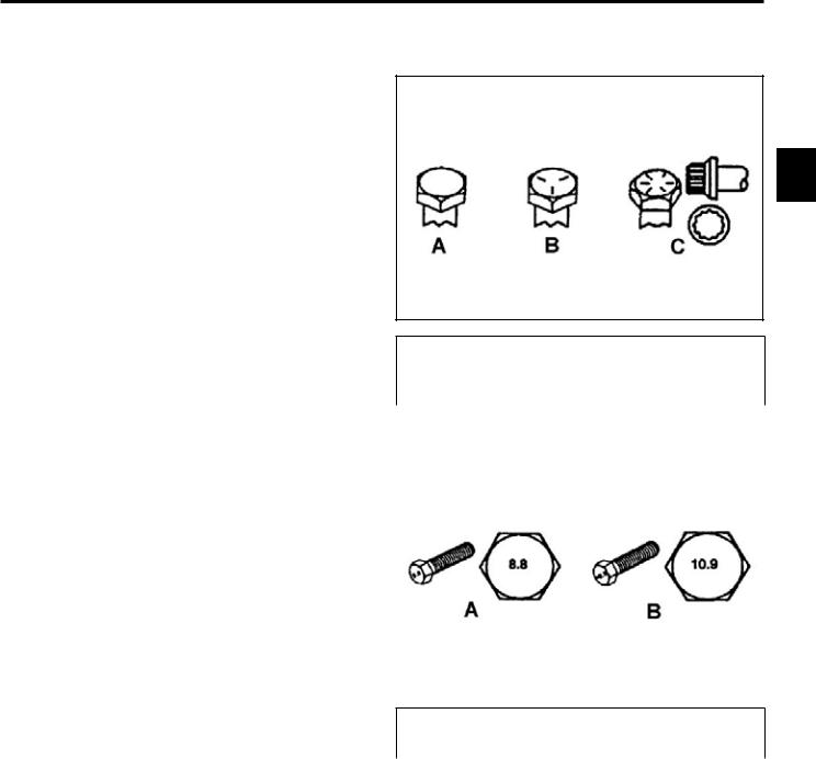
Fastener Identification
2
Inch Series bolts and Screws
(A) Grade 1 & 2 |
(C) Grade 8 |
|
(B) Grade 5 |
|
|
|
|
|
|
|
|
Metric Bolts and Screws
(A) Class 8.8 |
(B) Class 10.9 |
Toro Z Master G3 3000/5000/6000 Series Service Manual |
2-1 |
SPECIFICATIONS
Standard Torque for Dry, Zinc Plated & Steel Fasteners (Inch Series)
|
|
|
Grade 1, 5, & |
SAE Grade 1 Bolts, Screws, |
SAE Grade 5 Bolts, Screws, |
SAE Grade 8 Bolts, Screws, |
||||||||||||
|
|
Thread Size |
8 with Thin |
Studs, & Sems with Regular |
Studs, & Sems with Regular |
Studs, & Sems with Regular |
||||||||||||
|
|
Height Nuts |
Height Nuts (SAE J995 |
Height Nuts (SAE J995 |
Height Nuts (SAE J995 |
|||||||||||||
|
|
|
||||||||||||||||
|
|
|
|
|
Grade 2 or Stronger Nuts) |
Grade 2 or Stronger Nuts) |
Grade 2 or Stronger Nuts) |
|||||||||||
2 |
|
|
|
|
||||||||||||||
|
|
In-lb |
|
In-lb |
|
N-cm |
|
In-lb |
|
|
N-cm |
|
In-lb |
|
N-cm |
|
||
|
|
|
|
|
|
|
|
|
|
|
|
|
|
|
|
|
||
|
# 6 - 32 UNC |
10 |
± 2 |
13 |
± 2 |
147 |
± 23 |
15 |
± |
2 |
169 |
± 23 |
23 |
± 2 |
260 |
± 34 |
||
|
||||||||||||||||||
|
|
# 6 - 40 UNF |
17 |
± |
2 |
190 |
± 20 |
25 |
± 2 |
280 |
± 20 |
|||||||
|
|
|
|
|
|
|
|
|||||||||||
|
|
# 8 - 32 UNC |
13 |
± 2 |
25 |
± 5 |
282 |
± 30 |
29 |
± |
3 |
330 |
± 30 |
41 |
± 4 |
460 |
± 45 |
|
|
|
# 8 - 36 UNF |
31 ± 3 |
350 |
± 30 |
43 |
± 4 |
31 ± 3 |
||||||||||
|
|
|
|
|
|
|
|
|||||||||||
|
|
# 10 - 24 UNC |
18 |
± 2 |
30 |
± 5 |
339 |
± 56 |
42 |
± 4 |
475 |
± 45 |
60 |
± 6 |
674 |
± 70 |
||
|
|
#10 - 32 UNF |
48 |
± 4 |
540 |
± 45 |
68 |
± 6 |
765 |
± 70 |
||||||||
|
|
|
|
|
|
|
|
|||||||||||
|
|
1/4 - 20 UNC |
48 |
± 7 |
53 |
± 7 |
599 |
± 79 |
100 |
± 10 |
1125 ± 100 |
140 |
± 15 |
1580 |
± 170 |
|||
|
|
1/4 - 28 UNF |
53 |
± 7 |
65 ± 10 |
734 ± 113 |
115 ± 10 |
1300 |
± 100 |
160 |
± 15 |
1800 |
± 170 |
|||||
|
|
5/16 - 18 UNC |
115 ± 15 |
105 |
± 15 |
1186 ± 169 |
200 |
± 25 |
2250 |
± 280 |
300 |
± 30 |
3390 |
± 340 |
||||
|
|
5/16 - 24 UNF |
138 |
± 17 |
128 |
± 17 |
1446 |
± 192 |
225 |
± 25 |
2540 |
± 280 |
325 |
± 30 |
3670 |
± 340 |
||
|
|
|
ft-lb |
ft-lb |
N-m |
ft-lb |
N-m |
ft-lb |
N-m |
|||||||||
|
|
3/8 - 16 UNC |
16 |
± 2 |
16 |
± 2 |
22 |
± 3 |
30 |
± 3 |
41 |
± 4 |
43 |
± 4 |
58 |
± 5 |
||
|
|
3/8 - 24 UNF |
17 |
± 2 |
18 |
± 2 |
24 |
± 3 |
35 |
± 3 |
47 |
± 4 |
50 |
± 4 |
68 |
± 5 |
||
|
|
7/16 - 14 UNC |
27 |
± 3 |
27 |
± 3 |
37 |
± 4 |
50 |
± 5 |
68 |
± 7 |
70 |
± 7 |
68 |
± 9 |
||
|
|
7/16 - 20 UNF |
29 |
± 3 |
29 |
± 3 |
39 |
± 4 |
55 |
± 5 |
75 |
± 7 |
77 |
± 7 |
104 ± 9 |
|||
|
|
1/2 - 13 UNC |
30 |
± 3 |
48 |
± 7 |
65 |
± 9 |
75 |
± 8 |
102 ± 11 |
105 |
± 10 |
142 |
± 14 |
|||
|
|
1/2 - 20 UNF |
32 |
± 3 |
53 |
± 7 |
72 |
± 9 |
85 |
± 8 |
115 |
± 11 |
120 |
± 10 |
163 |
± 14 |
||
|
|
5/8 - 11 UNC |
65 ± 10 |
88 ± 12 |
119 |
± 16 |
150 |
± 15 |
203 |
± 20 |
210 |
± 20 |
285 |
± 27 |
||||
|
|
5/8 - 18 UNF |
75 ± 10 |
95 ± 15 |
129 |
± 20 |
170 |
± 15 |
230 |
± 20 |
240 |
± 20 |
325 |
± 27 |
||||
|
|
3/4 - 10 UNC |
93 ± 12 |
140 |
± 20 |
190 |
± 27 |
265 |
± 25 |
359 |
± 34 |
374 |
± 35 |
508 |
± 47 |
|||
|
|
3/4 - 16 UNF |
115 ± 15 |
165 |
± 25 |
224 |
± 34 |
300 |
± 25 |
407 |
± 34 |
420 |
± 35 |
569 |
± 47 |
|||
|
|
7/8 - 9 UNC |
140 |
± 20 |
225 |
± 25 |
305 |
± 34 |
430 |
± 45 |
583 |
± 61 |
600 |
± 60 |
813 |
± 81 |
||
|
|
7/8 - 14 UNF |
155 |
± 25 |
260 |
± 30 |
353 |
± 41 |
475 |
± 45 |
644 |
± 61 |
660 |
± 60 |
895 |
± 81 |
||
|
|
|
|
|
|
|
|
|
|
|
|
|
|
|
|
|
|
|
Note: Reduce torque values listed in the table above by 25% for lubricated fasteners. Lubricated fasteners are defined as threads coated with a lubricant such as oil, graphite, or thread sealant such as Loctite.
Note: Torque values may have to be reduced when installing fasteners into threaded aluminum or brass. The specific torque value should be determined based on the fastener size, the aluminum or base material strength, length of thread engagement, etc.
Note: The nominal torque values listed above for Grade 5 and 8 fasteners are based on 75% of the minimum proof load specified in SAE J429. The tolerance is approximately ± 10% of the nominal torque value. Thin height nuts include jam nuts.
2-2 |
Toro Z Master G3 3000/5000/6000 Series Service Manual |

SPECIFICATIONS
Standard Torque for Dry, Zinc & Steel Fasteners (Metric Fasteners)
|
Class 8.8 Bolts, Screws, and Studs with |
Class 10.9 Bolts, Screws, and Studs with |
|
|
|||||||
Thread Size |
|
Regular Height Nuts |
|
Regular Height Nuts ( |
|
|
|||||
|
|
(Class 8 or Strong Nuts) |
|
Class 10 or Strong Nuts) |
|
|
|||||
M5 X 0.8 |
57 ± 5 in-lb |
644 ± 68 N-cm |
78 ± 8 in-lb |
881 ± 90 N-cm |
|
|
|||||
2 |
|||||||||||
M6 X 1.0 |
96 ± 10 in-lb |
1085 ± 113 N-cm |
133 ± 14 in-lb |
1503 ± 158 N-cm |
|
||||||
M8 X 1.25 |
19 |
± 2 ft-lb |
26 |
± 3 N-m |
28 |
± 3 ft-lb |
38 |
± 4 N-m |
|
||
|
|||||||||||
M10 X 1.5 |
38 |
± 4 ft-lb |
52 |
± 5 N-m |
54 |
± 6 ft-lb |
73 |
± 8 N-m |
|
|
|
M12 X 1.75 |
66 |
± 7 ft-lb |
90 ± 10 N-m |
93 ± 10 ft-lb |
126 |
± 14 N-m |
|
|
|||
M16 X 2.0 |
166 |
± 15 ft-lb |
225 |
± 23 N-m |
229 |
± 23 ft-lb |
310 |
± 31 N-m |
|
|
|
M20 X 2.5 |
325 |
± 33 ft-lb |
440 |
± 45 N-m |
450 |
± 36 ft-lb |
610 |
± 62 N-m |
|
|
|
|
|
|
|
|
|
|
|
|
|
|
|
Note: Reduce torque values listed in the table above by 25% for lubricated fasteners. Lubricated fasteners are defined as threads coated with a lubricant such as oil, graphite, or thread sealant such as Loctite.
Note: Torque values may have to be reduced when installing fasteners into threaded aluminum or brass. The specific torque value should be determined based on the fastener size, the aluminum or base material strength, length of thread engagement, etc.
Note: The nominal torque values listed above are based on 75% of the minimum proof load specified in SAE J1199. The tolerance is approximately ± 10% of the nominal torque value. Thin height nuts include jam nuts.
Toro Z Master G3 3000/5000/6000 Series Service Manual |
2-3 |

SPECIFICATIONS
Other Torque Specifications
SAE Grade 8 Steel Set Screws
|
|
Thread Size |
Recommended Torque |
|
|
|
|
|
|
2 |
|
Square Head |
Hex Socket |
|
|
|
|||
|
|
|
|
|
|
1/4 - 20 UNC |
140 ± 20 in-lb |
73 ± 12 in-lb |
|
|
|
|
|
|
|
|
5/16 - 18 UNC |
215 ± 35 in-lb |
145 ± 20 in-lb |
|
|
|
|
|
|
|
3/8 - 16 UNC |
35 ± 10 ft-lb |
18 ± 3 ft-lb |
|
|
|
|
|
|
|
1/2 - 13 UNC |
75 ± 15 ft-lb |
50 ± 10 ft-lb |
|
|
|
|
|
Wheel Bolts and Lug Nuts
Thread Size |
Recommended Torque** |
||
|
|
|
|
7/16 - 20 UNF |
65 ± 10 ft-lb |
88 ± 14 N-m |
|
Grade 5 |
|||
|
|
||
|
|
|
|
1/2 - 20 UNF |
80 ± 10 ft-lb |
108 ± 14 N-m |
|
Grade 5 |
|||
|
|
||
|
|
|
|
M12 X 1.25 |
80 ± 10 ft-lb |
108 ± 14 N-m |
|
Class 8.8 |
|||
|
|
||
|
|
|
|
M12 X 1.5 |
80 ± 10 ft-lb |
108 ± 14 N-m |
|
Class 8.8 |
|||
|
|
||
** For steel wheels and non-lubricated fasteners.
Thread Cutting Screws
(Zinc Plated Steel)
Type 1, Type 23, or Type F
Thread Size |
Baseline Torque* |
|
|
No. 6 - 32 UNC |
20 ± 5 in-lb |
|
|
No. 8 - 32 UNC |
30 ± 5 in-lb |
|
|
No.10 - 24 UNC |
38 ± 7 in-lb |
|
|
1/4 - 20 UNC |
85 ± 15 in-lb |
|
|
5/16 - 18 UNC |
110 ± 20 in-lb |
|
|
3/8 - 16 UNC |
200 ± 100 in-lb |
|
|
Conversion Factors
in-lb X 11.2985 = N-cm
ft-lb X 1.3558 = N-m
Thread Cutting Screws
(Zinc Plated Steel)
Thread |
Threads per Inch |
Baseline Torque* |
||
|
|
|||
Size |
Type A |
Type B |
||
|
||||
|
|
|||
|
|
|
|
|
No. 6 |
18 |
20 |
20 ± 5 in-lb |
|
|
|
|
|
|
No. 8 |
15 |
18 |
30 ± 5 in-lb |
|
|
|
|
|
|
No. 10 |
12 |
16 |
38 ± 7 in-lb |
|
|
|
|
|
|
No. 12 |
11 |
14 |
85 ± 15 in-lb |
|
* Hole size, material strength, material thickness and finish must be considered when determining specific torque values. All torque values are based on nonlubricated fasteners.
N-cm X - 0.08851 = in-lb
N-cm X 0.73776 = ft-lb
2-4 |
Toro Z Master G3 3000/5000/6000 Series Service Manual |

SPECIFICATIONS
Equivalents & Conversions
Decimal & Millimeter Equivalents
Fractions |
Decimals |
mm |
Fractions |
|
Decimals |
mm |
|
|
|
2 |
|||||||
|
|
|
|
|
|
|
|
|
|
|
|
|
|
|
|
|
|
1/64 |
0.015625 |
0.397 |
|
33/64 |
0.515625 |
13.097 |
|
|
|
|
|
|
|
|
|
|
|
1/32 |
0.03125 |
0.794 |
16/32 |
|
0.53125 |
13.484 |
|
|
|
|
|
|
|
|
|
|
|
3/64 |
0.046875 |
1.191 |
|
35/64 |
0.546875 |
13.891 |
|
|
|
|
|
|
|
|
|
|
|
1/16 |
0.0625 |
1.588 |
9/16 |
|
0.5625 |
14.288 |
|
|
|
|
|
|
|
|
|
|
|
5/64 |
0.078125 |
1.984 |
|
37/64 |
0.578125 |
14.684 |
|
|
|
|
|
|
|
|
|
|
|
3/32 |
0.9375 |
2.381 |
19/32 |
|
0.59375 |
15.081 |
|
|
|
|
|
|
|
|
|
|
|
1/8 |
0.1250 |
3.175 |
5/8 |
|
0.6250 |
15.875 |
|
|
|
|
|
|
|
|
|
|
|
9/64 |
0.140625 |
3.572 |
|
41/64 |
0.640625 |
16.272 |
|
|
|
|
|
|
|
|
|
|
|
5/32 |
0.15625 |
3.969 |
21/32 |
|
0.65625 |
16.669 |
|
|
|
|
|
|
|
|
|
|
|
11/64 |
0.171875 |
4.366 |
|
43/64 |
0.671875 |
17.066 |
|
|
|
|
|
|
|
|
|
|
|
3/16 |
0.1875 |
4.762 |
11/16 |
|
0.6875 |
17.462 |
|
|
|
|
|
|
|
|
|
|
|
13/64 |
0.203125 |
5.159 |
|
45/64 |
0.703125 |
17.859 |
|
|
|
|
|
|
|
|
|
|
|
7/32 |
0.21875 |
5.556 |
23/32 |
|
0.71875 |
18.256 |
|
|
|
|
|
|
|
|
|
|
|
15/64 |
0.234375 |
5.953 |
|
47/64 |
0.734375 |
18.653 |
|
|
|
|
|
|
|
|
|
|
|
1/4 |
0.2500 |
6.350 |
3/4 |
|
0.7500 |
19.050 |
|
|
|
|
|
|
|
|
|
|
|
17/64 |
0.265625 |
6.747 |
|
49/64 |
0.765625 |
19.447 |
|
|
|
|
|
|
|
|
|
|
|
9/32 |
0.28125 |
7.144 |
25/32 |
|
0.78125 |
19.844 |
|
|
|
|
|
|
|
|
|
|
|
19/64 |
0.296875 |
7.541 |
|
51/64 |
0.796875 |
20.241 |
|
|
|
|
|
|
|
|
|
|
|
5/16 |
0.3125 |
7.541 |
13/16 |
|
0.8125 |
20.638 |
|
|
|
|
|
|
|
|
|
|
|
21/64 |
0.328125 |
8.334 |
|
53/64 |
0.828125 |
21.034 |
|
|
|
|
|
|
|
|
|
|
|
11/32 |
0.34375 |
8.731 |
27/32 |
|
0.84375 |
21.431 |
|
|
|
|
|
|
|
|
|
|
|
23/64 |
0.359375 |
9.128 |
|
55/64 |
0.859375 |
21.828 |
|
|
|
|
|
|
|
|
|
|
|
3/8 |
0.3750 |
9.525 |
7/8 |
|
0.8750 |
22.225 |
|
|
|
|
|
|
|
|
|
|
|
25/64 |
0.390625 |
9.922 |
|
57/64 |
0.890625 |
22.622 |
|
|
|
|
|
|
|
|
|
|
|
13/32 |
0.40625 |
10.319 |
29/32 |
|
0.90625 |
23.019 |
|
|
|
|
|
|
|
|
|
|
|
27/64 |
0.421875 |
10.716 |
|
59/64 |
0.921875 |
23.416 |
|
|
|
|
|
|
|
|
|
|
|
7/16 |
0.4375 |
11.112 |
15/16 |
|
0.9375 |
23.812 |
|
|
|
|
|
|
|
|
|
|
|
29/64 |
0.453125 |
11.509 |
|
61/64 |
0.953125 |
24.209 |
|
|
|
|
|
|
|
|
|
|
|
15/32 |
0.46875 |
11.906 |
31/32 |
|
0.96875 |
24.606 |
|
|
|
|
|
|
|
|
|
|
|
31/64 |
0.484375 |
12.303 |
|
63/64 |
0.984375 |
25.003 |
|
|
|
|
|
|
|
|
|
|
|
1/2 |
0.5000 |
12.700 |
1 |
|
1.000 |
25.400 |
|
|
|
|
|
|
|
|
|
|
|
1 mm = 0.03937 in. |
|
|
0.001 in. = 0.0254 mm |
|
|
|
||
|
|
|
|
|
|
|
|
|
Toro Z Master G3 3000/5000/6000 Series Service Manual |
2-5 |

SPECIFICATIONS
U.S. to Metric Conversions
|
|
|
To Convert |
Into |
Multiply By |
|
|
|
|
|
|
|
|
|
|
|
|
|
|
|
|
|
|
Miles |
Kilometers |
|
1.609 |
|
|
|
Yards |
Meters |
|
0.9144 |
2 |
|
|
|
|||
|
Linear |
Feet |
Meters |
|
0.3048 |
|
|
Feet |
Centimeters |
|
30.48 |
||
|
Measurement |
Inches |
Meters |
|
||
|
|
0.0254 |
||||
|
|
|
Inches |
Centimeters |
|
2.54 |
|
|
|
Inches |
Millimeters |
|
|
|
|
|
|
25.4 |
||
|
|
|
|
|
|
|
|
|
|
|
|
|
|
|
|
|
Square Miles |
Square Kilometers |
|
2.59 |
|
|
Area |
Square Feet |
Square Meters |
|
0.0929 |
|
|
Square Inches |
Square Centimeters |
|
6.452 |
|
|
|
|
|
|||
|
|
|
Acre |
Hectare |
|
0.4047 |
|
|
|
|
|
|
|
|
|
|
|
|
|
|
|
|
|
Cubic Yards |
Cubic Meters |
|
0.7646 |
|
|
Volume |
Cubic Feet |
Cubic Meters |
|
0.02832 |
|
|
|
Cubic Inches |
Cubic Centimeters |
|
16.39 |
|
|
|
|
|
|
|
|
|
|
Tons (Short) |
Metric Tons |
|
0.9078 |
|
|
Weight |
Pounds |
Kilograms |
|
0.4536 |
|
|
|
Ounces |
Grams |
|
28.3495 |
|
|
|
|
|
|
|
|
|
Pressure |
Pounds/Sq. In. |
Kilopascal |
|
6.895 |
|
|
|
|
|
|
|
|
|
|
Foot-pounds |
Newton-Meters |
|
1.356 |
|
|
Work |
Foot-pounds |
Kilogram-Meters |
|
0.1383 |
|
|
|
Inch-pounds |
Kilogram-Centimeters |
|
1.152144 |
|
|
|
|
|
|
|
|
|
Liquid Volume |
Quarts |
Liters |
|
0.9463 |
|
|
Gallons |
Liters |
|
3.785 |
|
|
|
|
|
|||
|
|
|
|
|
|
|
|
|
Liquid Flows |
Gallons/Minute |
Liters/Minute |
|
3.785 |
|
|
|
|
|
|
|
|
|
Temperature |
Fahrenheit |
Celsius |
1. |
Subtract 32° |
|
|
|
|
2. |
Multiply by 5/9 |
|
|
|
|
|
|
||
|
|
|
|
|
|
|
2-6 |
Toro Z Master G3 3000/5000/6000 Series Service Manual |

SPECIFICATIONS
G3 3000/5000/6000 Series Specifications
Engines: |
|
20.5 hp (15.4kW) |
|
22 hp (16.2 kW) |
|
23.5 hp (17.6kW) |
|
|
24 hp (17.9 kW) |
|
|
|||||||||||
Make |
|
|
Kawasaki |
|
|
Kawasaki FX |
|
|
Kawasaki |
|
|
|
|
Kawasaki FX |
|
|
||||||
Model |
|
|
FX651V |
|
|
FX691V |
|
|
FX730V |
|
|
|
|
FX691V |
|
|
||||||
|
|
|
|
|
|
|
|
|
|
|
|
|
|
|
|
|
2 |
|||||
Hi-Idle |
|
3600 ±100 RPM |
|
3600 ± 100 RPM |
|
3600 ±100 RPM |
|
|
3600 ± 100 RPM |
|
||||||||||||
Low-Idle |
|
|
1550 RPM |
|
|
1550 RPM |
|
|
1550 RPM |
|
|
|
|
1800 RPM |
|
|||||||
Spark Plug |
|
NGK BPR4ES |
|
NGK BPR4ES |
|
NGK BPR4ES |
|
|
|
NGK BPR4ES |
|
|
||||||||||
Oil |
|
SAE 10w-30 / |
|
SAE 10w-30 / |
|
SAE 10w-30 / |
|
|
|
|
SAE 10w-30 / |
|
|
|||||||||
|
|
|
SAE10w-40 |
|
|
SAE10w-40 |
|
SAE10w-40 |
|
|
|
|
SAE10w-40 |
|
|
|||||||
Oil Capacity |
|
2.2Qt. (2.1 L) |
|
|
2.2 Qt. (2.1 L) |
|
2.2 Qt. (2.1 L) |
|
|
|
|
2.2 Qt. (2.1 L) |
|
|
||||||||
CARB |
|
|
No |
|
|
|
|
No |
|
|
|
|
78924 |
|
|
|
78922 / 78926 78928 |
|
|
|||
EPA |
|
|
Yes |
|
|
|
|
Yes |
|
|
|
|
Yes |
|
|
|
|
Yes |
|
|
||
Heavy Duty Air |
|
|
Standard |
|
|
Standard |
|
|
Standard |
|
|
|
|
Standard |
|
|
||||||
Canister |
|
|
|
|
|
|
|
|
|
|
|
|
||||||||||
|
|
|
|
|
|
|
|
|
|
|
|
|
|
|
|
|
|
|
|
|
|
|
Engines: |
|
|
|
|
|
|
|
|
|
|
|
|||||||||||
|
|
24.5 hp (18.5 kW) |
25.5 hp (19.2 kW) |
|
25.5 hp (19.2 kW) |
|
|
|||||||||||||||
Make |
|
|
|
|
Kawasaki |
|
|
Kawasaki |
|
|
Kawasaki (Propane) |
|
|
|||||||||
Model |
|
|
|
|
FX751V |
|
|
FX801V |
|
|
|
|
|
|
FX801V |
|
|
|||||
Hi-Idle |
|
|
3600 ± 100 RPM |
3600 ± 100 RPM |
|
|
|
3750 ± 50 RPM |
|
|
||||||||||||
Low-Idle |
|
|
|
1550 RPM |
|
|
1550 RPM |
|
|
|
|
|
1550 RPM |
|
|
|||||||
Spark Plug |
|
|
NGK BPR4ES |
NGK BPR4ES |
|
|
|
NGK BPR4ES |
|
|
||||||||||||
Oil |
|
|
SAE 10w-30 / SAE10w-40 |
SAE 10w-30 / SAE10w-40 |
|
SAE 10w-30 / SAE10w-40 |
|
|
||||||||||||||
Oil Capacity |
|
|
2.2 Qt. (2.1 L) |
2.2 Qt. (2.1 L) |
|
|
|
1.9 Qt. (1.8 L) |
|
|
||||||||||||
CARB |
|
|
|
|
|
No |
|
|
|
No |
|
|
|
|
|
|
|
|
No |
|
|
|
EPA |
|
|
|
|
|
Yes |
|
|
|
Yes |
|
|
|
|
|
|
|
|
Yes |
|
|
|
Heavy Duty Air Canister |
|
|
Standard |
|
|
Standard |
|
|
|
|
|
|
Standard |
|
|
|||||||
Engines: |
|
|
|
|
|
|
|
|
|
|
||||||||||||
23 hp (17.2 kW) |
|
25 hp (18.6 kW) |
27 hp (20.1 kW) |
|
|
29 hp (21.6 kW) |
|
34 hp (25.4 kW) |
|
|
||||||||||||
Make |
Kohler Command |
|
Kohler Command |
Kohler Command |
|
Kohler EFI |
|
|
Kohler Command |
|
|
|||||||||||
|
|
|
|
|
|
|
|
|
Pro |
|
|
|
|
|
|
|
|
|
|
|
||
Model |
|
CV680S |
|
|
CV730S |
CV740S |
|
|
ECV749 |
|
|
FH921V |
|
|
||||||||
Hi-Idle |
3800 ± 50 RPM |
|
3800 ± 50 RPM |
3800 ± 50 RPM |
|
|
3800 ± 50 RPM |
|
3600 ± 100 |
|
|
|||||||||||
Low-Idle |
|
1800 RPM |
|
|
1800 RPM |
1800 RPM |
|
|
1800 RPM |
|
|
1550 RPM |
|
|
||||||||
Spark Plug |
|
Champion |
|
|
Champion |
Champion |
|
|
Champion |
|
|
NGK BPR5ES |
|
|
||||||||
|
|
R12YC |
|
|
R12YC |
R12YC |
|
|
R12YC |
|
|
|
|
|||||||||
|
|
|
|
|
|
|
|
|
|
|
||||||||||||
Oil |
SAE 10w-30 / |
|
|
SAE 10w-30 / |
SAE 10w-30 / |
|
|
SAE 10w-30 / |
|
|
SAE 10w-30 / |
|
|
|||||||||
|
|
SAE10w-40 |
|
|
SAE10w-40 |
SAE10w-40 |
|
|
SAE10w-40 |
|
|
SAE10w-40 |
|
|
||||||||
Oil Capacity |
2.0 Qt. (1.9 L) |
|
|
2.0 Qt. (1.9 L) |
2.0 Qt. (1.9 L) |
|
|
2.0 Qt. (1.9 L) |
|
1.8 Qt. (1.7 L) |
|
|
||||||||||
CARB |
|
No |
|
|
|
No |
No |
|
|
No |
|
|
No |
|
|
|||||||
EPA |
|
Yes |
|
|
|
Yes |
Yes |
|
|
Yes |
|
|
Yes |
|
|
|||||||
Heavy Duty Air |
|
Standard |
|
|
Standard |
Standard |
|
|
Standard |
|
|
Standard |
|
|
||||||||
Canister |
|
|
|
|
|
|
|
|
|
|||||||||||||
|
|
|
|
|
|
|
|
|
|
|
|
|
|
|
|
|
|
|
|
|
|
|
Toro Z Master G3 3000/5000/6000 Series Service Manual |
2-7 |

SPECIFICATIONS
G3 3000/5000/6000 Series Specifications cont.
|
|
Fuel System: |
|
|
|
|
|
|
|
|
|
|
|
Fuel Tank Capacity |
|
8 Gallon (US) (26.5 L) |
|
12 Gallon (US) (45.4 L) |
|
43.5 lb Propane (19.7 kg) |
|||
|
|
Fuel Gauge |
|
|
Located on top of tank. |
|
|
|
Located on tank |
||
|
|
Fuel Delivery System |
|
|
Fuel pump |
|
|
|
Vapor draw |
||
2 |
|
|
|
|
|
||||||
|
Traction Drives: |
|
|
|
|
|
|
|
|
|
|
|
|
|
|
|
|
|
|
|
|
|
|
|
|
Hydraulic Drive |
|
|
|
|
Unitized Pump & Motor |
|
|
||
|
|
System |
|
|
|
|
|
|
|||
|
|
|
|
|
|
|
|
|
|
|
|
|
|
Pump |
12cc No Fans |
12cc w/Check Valve |
12cc w/Shock Valve |
16cc w/Shock Valve |
|||||
|
|
Motor |
|
14.6 cir |
|
14.6 cir |
14.6 cir |
|
17.1 cir |
||
|
|
Hydraulic Fluid |
|
Toro Hypr-Oil (500 hr service) or Mobil 1 15w50 Motor Oil (250 hr service) |
|||||||
|
|
Hydraulic Fluid |
|
|
52 oz. (1.5 liters) per side w/ filter change |
|
|||||
|
|
Capacity |
|
|
|
||||||
|
|
|
|
|
|
|
|
|
|
|
|
|
|
Ground Speed |
0 to 8 mph fwd |
0 to 10 mph fwd |
0 to 10 mph fwd |
0 to 12 mph fwd |
|||||
|
|
Release Valves |
|
External lever on each unit. Allow unit to be moved without engine running |
|||||||
|
|
Pump drive |
|
|
Belt tension via spring loaded idler |
|
|
||||
|
|
|
|
|
|
|
|
|
|
||
|
|
Mowing Decks: |
|
48” |
|
52” |
60” |
|
72” |
||
|
|
Cutting Deck |
Turbo Force |
Turbo Force |
Turbo Force |
|
Turbo Force |
||||
|
|
Cutting Height |
|
1.0” to 5.5” (25.4mm - 139.7mm) in .25” (6.3mm) increments |
|||||||
|
|
Blade Tip Speed |
18500 + ft/min |
18500 + ft/min |
18500 + ft/min |
|
18500 + ft/min |
||||
|
|
Spindle |
Standard Greasable |
Standard Greasable |
Standard Greasable |
Tapered Roller or |
|||||
|
|
|
Greasable Ball |
||||||||
|
|
|
Ball Bearing |
Ball Bearing |
Ball Bearing |
|
|||||
|
|
|
|
Bearing |
|||||||
|
|
|
|
|
|
|
|
|
|
|
|
|
|
Configuration |
|
|
Tools Adjust or Hand Adjust Baffle |
|
|
||||
|
|
Clutch |
|
Models with 29 hp and under utilize a 200 ft-lb clutch. |
|||||||
|
|
|
|
|
Models above 29 hp utilize a 250 ft-lb clutch. |
|
|||||
|
|
PTO Idler |
|
|
|
Spring-loaded idler system |
|
|
|||
|
|
Construction |
|
7 gauge (.179”/ 4.5mm) Steel Welded Construction |
|||||||
|
|
Blades |
16.5” long, .250” |
18.0” long, .250” |
20.5” long, .250” |
24.5” long, .250” |
|||||
|
|
|
thick, 2.5” wide, heat |
thick, 2.5” wide, heat |
thick, 2.5” wide, heat |
thick, 2.5” wide, heat |
|||||
|
|
|
treated steel blades, |
treated steel blades, |
treated steel blades, |
treated steel blades, |
|||||
|
|
|
|
qty 3 |
|
qty 3 |
qty 3 |
|
qty 3 |
||
2-8 |
Toro Z Master G3 3000/5000/6000 Series Service Manual |

SPECIFICATIONS
G3 3000/5000/6000 Series Specifications cont.
Electrical System: |
|
|
|
|
|
Voltage |
12 volt, negative ground |
|
|
|
|
Battery Type |
Wet-Battery |
|
|
|
|
Fuses |
Blade Type |
|
|
|
|
2 |
|||||
Hourmeter with |
Standard Equipment |
|
|
||
Service Indicator |
|
|
|||
|
|
|
|
||
Controls: |
|
|
|
|
|
Steering Levers |
Dual, wrap-around, hydraulic dampened, with cushioned grips |
|
|
||
Parking Brake |
Right hand operated lever with cushioned grip |
|
|
||
Deck Lift |
Foot lift assist via foot pedal |
|
|
||
Cutting Height |
Controlled by keyed height of cut pin |
|
|
||
Toro Z Master G3 3000/5000/6000 Series Service Manual |
2-9 |

SPECIFICATIONS
Dimensions
Commercial 3000 Series
|
|
|
|
Overall Length |
|
|
|
Overall Height |
|
||
2 |
|
|
|
|
|
Width |
Overall |
|
|
|
|
|
|
Wheel |
ROPS |
ROPS |
Width |
Gate |
ROPS |
ROPS |
|
||
|
|
Outside |
Weight |
||||||||
|
Model # |
Base |
Up |
Folded |
(Chute |
Width |
Up |
Folded |
|||
|
|
|
|
|
|
Tires |
Down) |
|
|
|
|
|
|
|
|
|
|
|
|
|
|
|
|
|
|
|
in./cm |
in./cm |
in./cm |
in./cm |
in./cm |
in./cm |
in./cm |
in./cm |
lbs./kg |
|
|
74952 |
47.7/ |
79.2/ |
80.9/ |
45.7/ |
63.6/ |
54.0/ |
70.5/ |
46.8/ |
1120/ |
|
|
121.2 |
201.2 |
205.5 |
116.1 |
161.5 |
137.2 |
179.1 |
118.9 |
508.0 |
|
|
|
|
|||||||||
|
|
74953 |
47.7/ |
79.2/ |
80.9/ |
45.7/ |
67.6/ |
57.5/ |
70.5/ |
46.8/ |
1168/ |
|
|
121.2 |
201.2 |
205.5 |
116.1 |
171.7 |
146.1 |
179.1 |
118.9 |
529.8 |
|
|
|
|
|||||||||
|
|
74954 |
50.6/ |
83.1/ |
84.8/ |
53.0/ |
75.7/ |
61.7/ |
70.5/ |
46.8/ |
1165/ |
|
|
128.5 |
211.1 |
215.4 |
134.6 |
192.2 |
156.8 |
179.1 |
118.9 |
528.0 |
|
|
|
|
|||||||||
G3/Professional 5000 Series
|
|
|
|
|
|
Overall Height |
|
||
|
|
|
Width |
Overall |
|
|
|
|
|
|
Wheel |
Overall |
Width |
Gate |
|
ROPS |
|
||
|
Outside |
ROPS Up |
Weight |
||||||
Model # |
Base |
Length |
(Chute |
Width |
Folded |
||||
Tires |
|
|
|||||||
|
|
|
Down) |
|
|
|
|
||
|
|
|
|
|
|
|
|
||
|
in./cm |
in./cm |
in./cm |
in./cm |
in./cm |
in./cm |
in./cm |
lbs./kg |
|
74901 |
47.7/121.2 |
79.2/201.2 |
45.7/116.1 |
63.6/161.5 |
54.0/137.2 |
70.5/179.1 |
46.8/118.9 |
1120/ |
|
508.0 |
|||||||||
|
|
|
|
|
|
|
|
||
74903 |
47.7/121.2 |
79.2/201.2 |
45.7/116.1 |
67.6/171.7 |
57.5/146.1 |
70.5/179.1 |
46.8/118.9 |
1168/ |
|
529.8 |
|||||||||
|
|
|
|
|
|
|
|
||
74915 |
50.6/128.5 |
83.1/211.1 |
53.0/134.6 |
75.7/192.3 |
61.7/156.7 |
70.5/179.1 |
46.8/118.9 |
1216/ |
|
551.6 |
|||||||||
|
|
|
|
|
|
|
|
||
74916 |
53.6/136.1 |
86.1/218.7 |
59.1/150.1 |
87.6/222.5 |
73.6/186.9 |
70.5/179.1 |
46.8/118.9 |
1296/ |
|
588.0 |
|||||||||
|
|
|
|
|
|
|
|
||
74930 |
50.6/128.5 |
83.1/211.1 |
53.0/134.6 |
75.7/192.3 |
61.7/156.7 |
70.5/179.1 |
46.8/118.9 |
1255/ |
|
569.0 |
|||||||||
|
|
|
|
|
|
|
|
||
2-10 |
Toro Z Master G3 3000/5000/6000 Series Service Manual |

SPECIFICATIONS
Dimensions
G3/Professional 6000 Series
|
|
|
|
|
|
Overall Height |
|
|
|
|
|
|
|
Width |
Overall |
|
|
|
|
|
2 |
|
Wheel |
Overall |
Width |
Gate |
|
ROPS |
|
|
||
|
Outside |
ROPS Up |
Weight |
|
||||||
Model # |
Base |
Length |
(Chute |
Width |
Folded |
|
||||
|
|
|
Tires |
Down) |
|
|
|
|
|
|
|
|
|
|
|
|
|
|
|
|
|
|
in./cm |
in./cm |
in./cm |
in./cm |
in./cm |
in./cm |
in./cm |
lbs./kg |
|
|
74922 |
47.7/121.2 |
79.2/201.2 |
45.7/116.1 |
63.6/161.5 |
54.0/137.2 |
70.5/179.1 |
46.8/118.9 |
1147/ |
|
|
520.3 |
|
|
||||||||
|
|
|
|
|
|
|
|
|
|
|
74923 |
47.7/121.2 |
79.2/201.2 |
45.7/116.1 |
63.6/161.5 |
54.0/137.2 |
70.5/179.1 |
46.8/118.9 |
1147/ |
|
|
520.3 |
|
|
||||||||
|
|
|
|
|
|
|
|
|
|
|
74925 |
50.6/128.5 |
83.1/211.1 |
53.0/134.6 |
75.7/192.3 |
61.7/156.7 |
70.5/179.1 |
46.8/118.9 |
1254/ |
|
|
568.8 |
|
|
||||||||
|
|
|
|
|
|
|
|
|
|
|
74926 |
50.6/128.5 |
83.1/211.1 |
53.0/134.6 |
75.7/192.3 |
61.7/156.7 |
70.5/179.1 |
46.8/118.9 |
1255/ |
|
|
569.3 |
|
|
||||||||
|
|
|
|
|
|
|
|
|
|
|
74927 |
53.6/136.1 |
86.1/218.7 |
59.1/150.1 |
87.6/222.5 |
73.6/186.9 |
70.5/179.1 |
46.8/118.9 |
1334/ |
|
|
605.1 |
|
|
||||||||
|
|
|
|
|
|
|
|
|
|
|
74928 |
53.6/136.1 |
86.1/218.7 |
59.1/150.1 |
87.6/222.5 |
73.6/186.9 |
70.5/179.1 |
46.8/118.9 |
1350/ |
|
|
612.3 |
|
|
||||||||
|
|
|
|
|
|
|
|
|
|
|
74935 |
50.6/128.5 |
83.1/211.1 |
53.0/134.6 |
75.7/192.3 |
61.7/156.7 |
70.5/179.1 |
46.8/118.9 |
1269/ |
|
|
575.6 |
|
|
||||||||
|
|
|
|
|
|
|
|
|
|
|
74936 |
50.6/128.5 |
83.1/211.1 |
53.0/134.6 |
75.7/192.3 |
61.7/156.7 |
70.5/179.1 |
46.8/118.9 |
1269/ |
|
|
575.6 |
|
|
||||||||
|
|
|
|
|
|
|
|
|
|
|
74937 |
53.6/136.1 |
86.1/218.7 |
59.1/150.1 |
87.6/222.5 |
73.6/186.9 |
70.5/179.1 |
46.8/118.9 |
1349/ |
|
|
611.9 |
|
|
||||||||
|
|
|
|
|
|
|
|
|
|
|
74938 |
53.6/136.1 |
86.1/218.7 |
59.1/150.1 |
87.6/222.5 |
73.6/186.9 |
70.5/179.1 |
46.8/118.9 |
1349/ |
|
|
611.9 |
|
|
||||||||
|
|
|
|
|
|
|
|
|
|
|
74975 |
50.6/128.5 |
83.1/211.1 |
53.0/134.6 |
75.7/192.3 |
61.7/156.7 |
70.5/179.1 |
46.8/118.9 |
1255/ |
|
|
569.3 |
|
|
||||||||
|
|
|
|
|
|
|
|
|
|
|
74977 |
53.6/136.1 |
86.1/218.7 |
59.1/150.1 |
87.6/222.5 |
73.6/186.9 |
70.5/179.1 |
46.8/118.9 |
1352/ |
|
|
613.3 |
|
|
||||||||
|
|
|
|
|
|
|
|
|
|
|
78922 |
47.7/121.2 |
79.2/201.2 |
45.7/116.1 |
63.6/161.5 |
54.0/137.2 |
70.5/179.1 |
46.8/118.9 |
1147/ |
|
|
520.3 |
|
|
||||||||
|
|
|
|
|
|
|
|
|
|
|
78924 |
47.7/121.2 |
79.2/201.2 |
45.7/116.1 |
67.6/171.7 |
57.5/146.1 |
70.5/179.1 |
46.8/118.9 |
1147/ |
|
|
520.3 |
|
|
||||||||
|
|
|
|
|
|
|
|
|
|
|
78926 |
50.6/128.5 |
83.1/211.1 |
53.0/134.6 |
75.7/192.3 |
61.7/156.7 |
70.5/179.1 |
46.8/118.9 |
1255/ |
|
|
569.3 |
|
|
||||||||
|
|
|
|
|
|
|
|
|
|
|
78928 |
53.6/136.1 |
86.1/218.7 |
59.1/150.1 |
87.6/222.5 |
73.6/168.9 |
70.5/179.1 |
46.8/118.9 |
1350/ |
|
|
612.3 |
|
|
||||||||
|
|
|
|
|
|
|
|
|
|
|
Toro Z Master G3 3000/5000/6000 Series Service Manual |
2-11 |
SPECIFICATIONS
Dimensions
G3/Professional 6000 Series cont.
|
|
|
|
|
|
|
|
Overall Height |
|
|
2 |
|
|
|
|
Width |
Overall |
|
|
|
|
|
|
Wheel |
Overall |
Width |
Gate |
|
ROPS |
|
||
|
|
Outside |
ROPS Up |
Weight |
||||||
|
Model # |
Base |
Length |
(Chute |
Width |
Folded |
||||
|
|
|
|
|
Tires |
Down) |
|
|
|
|
|
|
|
|
|
|
|
|
|
|
|
|
|
|
in./cm |
in./cm |
in./cm |
in./cm |
in./cm |
in./cm |
in./cm |
lbs./kg |
|
|
74902TE |
47.7/121.2 |
79.2/201.2 |
45.7/116.1 |
63.6/161.5 |
54.0/137.2 |
70.5/179.1 |
46.8/118.9 |
1226/ |
|
|
556.0 |
||||||||
|
|
|
|
|
|
|
|
|
|
|
|
|
74923TE |
47.7/121.2 |
79.2/201.2 |
45.7/116.1 |
63.6/161.5 |
54.0/137.2 |
70.5/179.1 |
46.8/118.9 |
1190/ |
|
|
539.8 |
||||||||
|
|
|
|
|
|
|
|
|
|
|
|
|
74925TE |
50.6/128.5 |
83.1/211.1 |
53.0/134.6 |
75.7/192.3 |
61.7/156.7 |
70.5/179.1 |
46.8/118.9 |
1301/ |
|
|
590.1 |
||||||||
|
|
|
|
|
|
|
|
|
|
|
|
|
74941CP |
47.7/121.2 |
79.2/201.2 |
45.7/116.1 |
63.6/161.5 |
54.0/137.2 |
70.5/179.1 |
46.8/118.9 |
1205/ |
|
|
546.6 |
||||||||
|
|
|
|
|
|
|
|
|
|
|
|
|
74943CP |
47.7/121.2 |
79.2/201.2 |
45.7/116.1 |
67.6/171.7 |
57.5/146.1 |
70.5/179.1 |
46.8/118.9 |
1210/ |
|
|
548.8 |
||||||||
|
|
|
|
|
|
|
|
|
|
|
|
|
74945CP |
50.6/128.5 |
83.1/211.1 |
53.0/134.6 |
75.7/192.3 |
61.7/156.7 |
70.5/179.1 |
46.8/118.9 |
1254/ |
|
|
568.8 |
||||||||
|
|
|
|
|
|
|
|
|
|
|
|
|
74955CP |
50.6/128.5 |
83.1/211.1 |
53.0/134.6 |
75.7/192.3 |
61.7/156.7 |
70.5/179.1 |
46.8/118.9 |
1259/ |
|
|
571.1 |
||||||||
|
|
|
|
|
|
|
|
|
|
|
|
|
74957CP |
53.6/136.1 |
86.1/218.7 |
59.1/150.1 |
87.6/222.5 |
73.6/186.9 |
70.5/179.1 |
46.8/118.9 |
1350/ |
|
|
612.3 |
||||||||
|
|
|
|
|
|
|
|
|
|
|
|
|
74960CP |
50.6/128.5 |
83.1/211.1 |
53.0/134.6 |
75.7/192.3 |
61.7/156.7 |
70.5/179.1 |
46.8/118.9 |
1269/ |
|
|
575.6 |
||||||||
|
|
|
|
|
|
|
|
|
|
|
|
|
74961CP |
53.6/136.1 |
86.1/218.7 |
59.1/150.1 |
87.6/222.5 |
73.6/186.9 |
70.5/179.1 |
46.8/118.9 |
1349/ |
|
|
611.9 |
||||||||
|
|
|
|
|
|
|
|
|
|
|
2-12 |
Toro Z Master G3 3000/5000/6000 Series Service Manual |
CHASSIS
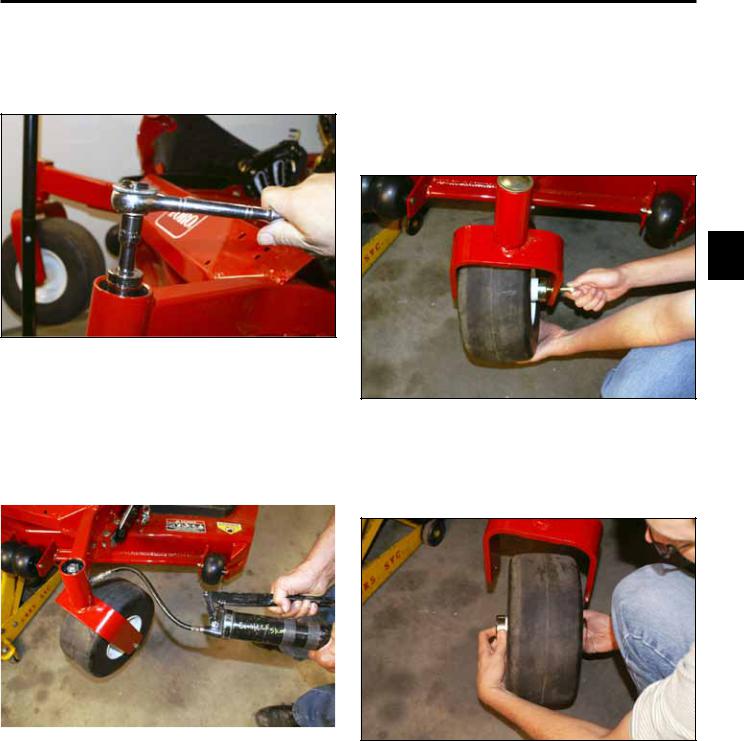
Caster Fork Assembly Replacement
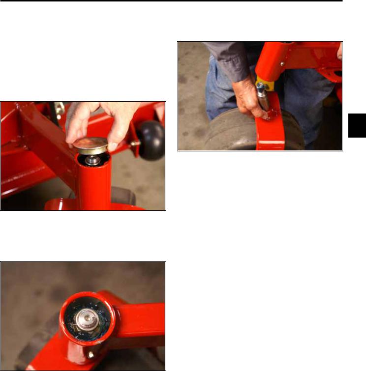
4.Slide the caster fork assembly out of the frame (Fig. 003).
Caster Fork Assembly Removal
1.Raise the front of the machine off the ground, leaving enough clearance to remove the caster fork from the frame.
2.Remove the grease cap from the frame (Fig. 001).
3
Fig. 003 |
PICT-0355 |
Fig. 001 |
PICT-0351 |
3. Remove the locknut (Fig. 002).
Fig. 002 |
PICT-0352a |
Toro Z Master G3 3000/5000/6000 Series Service Manual |
3-1 |
CHASSIS
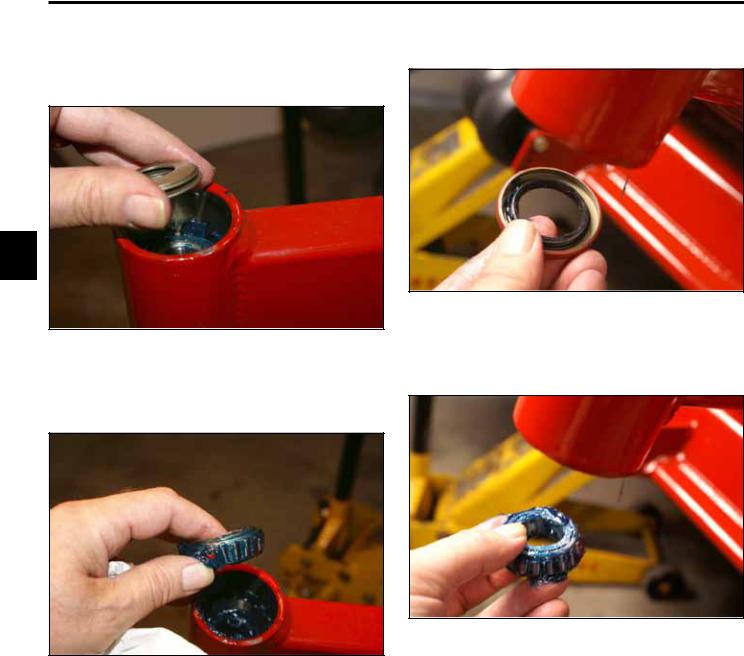
Caster Bearing Replacement |
3. Remove the bottom grease seal (Fig. 006). |
1. Remove the 3 Belleville washers (Fig. 004).
3
Fig. 006 |
PICT-0364a |
Fig. 004 |
PICT-0359a |
4. Remove the bottom tapered bearing (Fig. 007).
2. Remove the top tapered bearing (Fig. 005).
Fig. 007 |
PICT-0365 |
Fig. 005 |
PICT-0361a |
3-2 |
Toro Z Master G3 3000/5000/6000 Series Service Manual |
CHASSIS
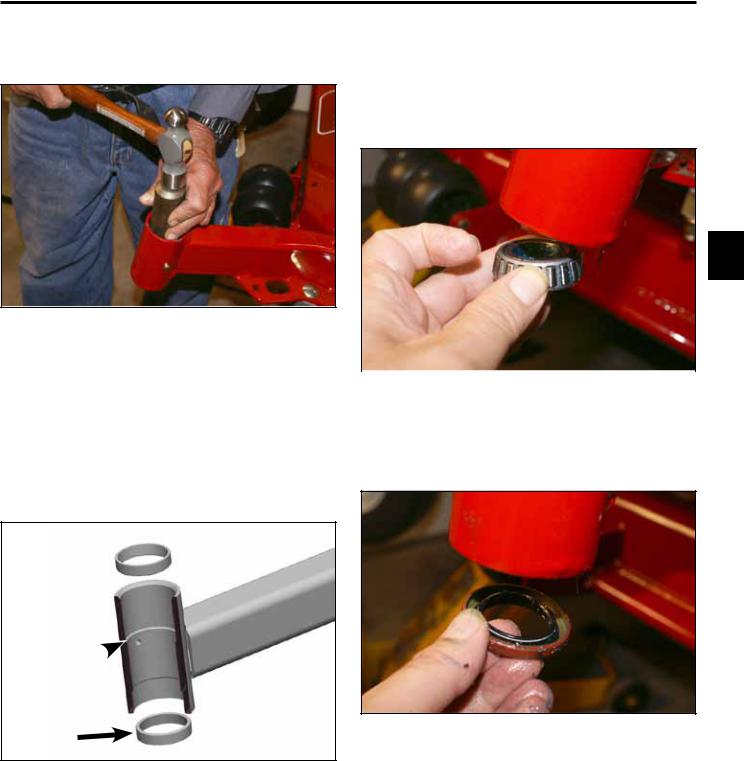
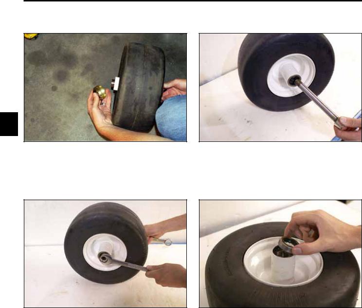
5.Drive the top and bottom tapered bearing cups out of the caster fork hub (Fig. 008).
7.Pack the upper and lower tapered bearings with grease (No. 2 general purpose lithium base or molybdenum grease).
8.Install the lower bearing into the caster fork hub (Fig. 010).
3
Fig. 008 |
PICT-0367a |
|
|
|
|
|
|
6. Install new tapered bearing cups by pressing each |
Fig. 010 |
PICT-0368a |
|
|
|
||
bearing cup into the caster fork hub so that the thick |
|
|
|
er part of the taper is pressed in first. The bearing |
|
|
|
cups should seat against the shoulder inside the |
9. Install the lower grease seal into the bottom of the |
||
frame. |
|
caster fork hub (Fig. 011). |
|
Section view of caster fork hub (Fig. 009).
A
B
C
A |
Fig. 011 |
PICT-0371a |
|
Fig 009 tapered bearing cup install
A.Tapered Bearing Cup (2)
B.Caster fork hub (sectioned)
C.Machined shoulder inside caster fork hub (2)
Toro Z Master G3 3000/5000/6000 Series Service Manual |
3-3 |

CHASSIS
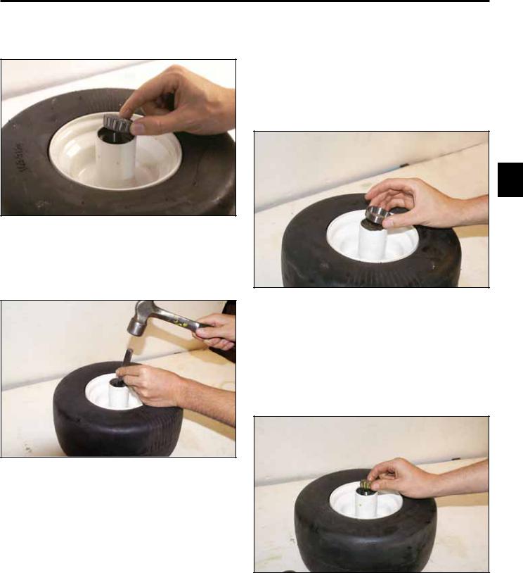
10. Install the upper bearing fork hub (Fig. 012). |
|
Caster Fork Assembly Installation |
|
|
1. Install 3 Belleville washers as shown (Fig. 013). |
|
|
|
|
|
|
|
|
C |
|
|
B |
3
|
|
A |
Fig. 012 |
PICT-0372a |
|
|
Fig. 013 |
fig. 69 G001297 |
A. |
Spring washer (3) |
C. |
Dust Cap |
B. |
Lock nut |
|
|
2. Slide the caster fork assembly into the hub (Fig. 014).
Fig. 014 |
PICT-0355 |
3-4 |
Toro Z Master G3 3000/5000/6000 Series Service Manual |
CHASSIS
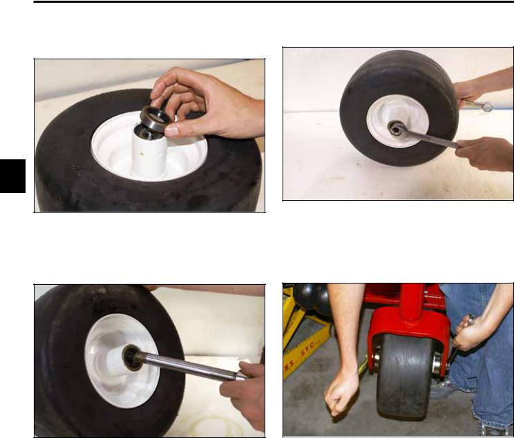
3.Install the locknut. Tighten the locknut until the Belleville washers are flat, then back the nut off 1/4 turn to properly set the preload on the bearings (Fig. 015).
Front Wheel Bearing Replacement
Front Wheel Bearing Removal
1.Raise the front of the machine off the ground.
2.Remove the wheel the axle bolt and nut (Fig. 017).
3
Fig. 015 PICT-0373a
4. Remove the plug located on the side of the caster |
Fig. 017 |
PICT-0378a |
hub. Install a grease fitting. Apply grease (No. 2 |
|
|
general purpose lithium base or molybdenum |
|
|
grease) into the hub until it passes through the upper |
3. Remove the wheel assembly from the fork (Fig. |
|
bearing. Fill the top cavity with grease (Fig. 016). |
||
|
018). |
|
|
|
|
Fig. 016 |
PICT-0375a |
Fig. 018 |
PICT-0379a |
5.Remove the grease fitting and install the grease plug.
Toro Z Master G3 3000/5000/6000 Series Service Manual |
3-5 |
CHASSIS
4. Remove the 2 seal guards (Fig. 019). |
6. Remove the axle caster (Fig. 021). |
3
Fig. 019 |
PICT-0380a |
Fig. 021 |
PICT-0383a |
5.Remove 2 spacer nuts from the axle caster (Fig. 020).
7.Remove the two caster seals from the wheel assembly (Fig. 022).
Fig. 020 |
PICT-0382a |
Fig. 022 |
PICT-0384a |
3-6 |
Toro Z Master G3 3000/5000/6000 Series Service Manual |
CHASSIS
8.Remove the 2 tapered bearings from the wheel assembly (Fig. 023).
Front Wheel Bearing Installation
1.Install a new tapered bearing cup into the wheel assembly by pressing each bearing cup into the wheel hub so that the thicker part of the taper is pressed into the wheel hub first. The bearing cups should seat against the shoulder divots inside the wheel hub (Fig. 025).
Fig. 023 |
PICT-0385a |
9.Drive the bearing cup out of the wheel assembly (Fig. 024).
3
Fig. 025 |
PICT-0389a |
2.Pack both tapered bearings with grease (No. 2 general purpose lithium base or molybdenum grease).
3.Install the tapered bearings into each side of the wheel hub (Fig. 026).
Fig. 024 |
PICT-0387a |
Fig. 026 |
PICT-0390a |
Toro Z Master G3 3000/5000/6000 Series Service Manual |
3-7 |
CHASSIS
4.Install the grease seals into each side of the wheel hub (Fig. 027).
6. Install the 2 spacer nuts and tighten (Fig. 029).
3
Fig. 029 |
PICT-0382a |
Fig. 027 |
PICT-0392a |
5. Install the caster axle (Fig. 028).
7.Install the two guard seals, screw, nut and tighten (Fig. 030).
Fig. 028 |
PICT-0393a |
Fig. 030 |
PICT-0394a |
3-8 |
Toro Z Master G3 3000/5000/6000 Series Service Manual |
CHASSIS
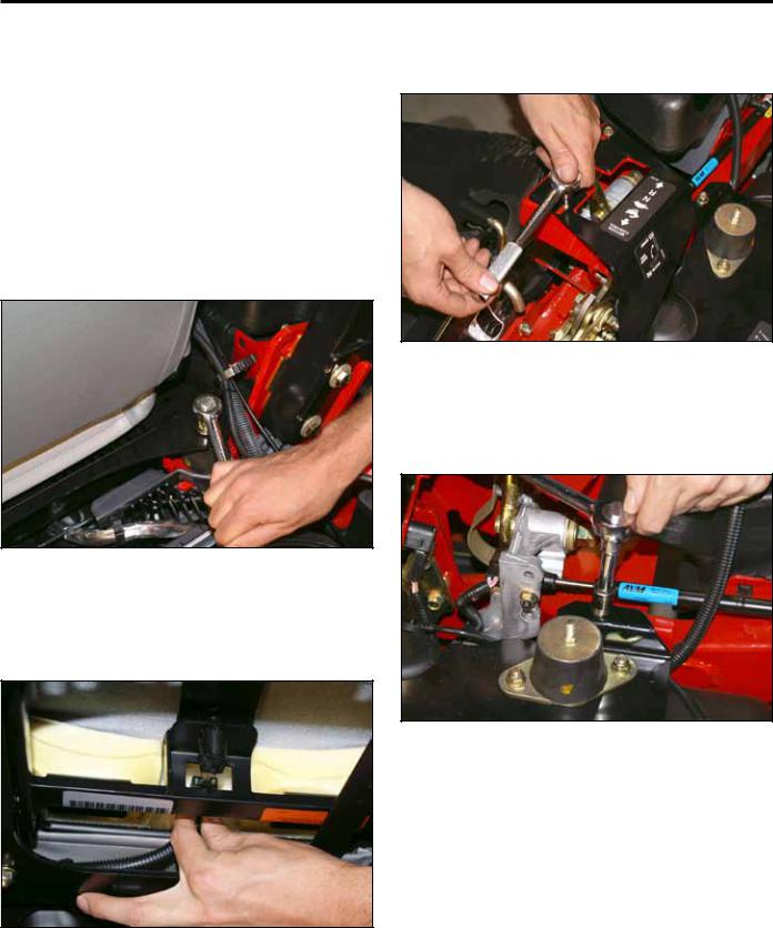
Fuel Tank Replacement
5.Remove the 4 screws retaining the right and left hand motion control covers (Fig. 033).
Fuel Tank Removal
1. |
Turn the fuel valve to the “Off” position. |
|
|
2. |
Siphon the fuel from the fuel tank. |
|
|
Note: The only recommended way to remove the |
|
||
|
fuel from the tank is by using a siphon pump. |
|
|
3. |
Remove the 4 bolts retaining the seat base as |
|
|
3 |
|||
|
sembly to the frame (Fig. 031). |
||
|
|
||
|
|
|
|
Fig. 033 PICT-0412a
6.Remove the two bolts and nuts retaining the seat mount to the frame (Fig. 034).
Fig. 031 |
PICT-0396a |
4.Lift the seat up enough to remove the wiring plug to the seat switch (Fig. 032).
Fig. 034 |
PICT-0413a |
Fig. 032 |
PICT-0398a |
Toro Z Master G3 3000/5000/6000 Series Service Manual |
3-9 |
Loading...