


 Loading...
Toro 74538, 74539, 74548, 74550, 74549 Service Manual
...
LCE Products
Toro GrandStand
Stand-on Mower
Service Manual

ABOUT THIS MANUAL
This service manual was written expressly for Toro and Lawn-Boy service technicians. The Toro Company has made every effort to make the information in this manual complete and correct.
Basic shop safety knowledge and mechanical/electrical skills are assumed. The Table of Contents lists the systems and the related topics covered in this manual.
For additional information on the electrical system, please refer to the Toro Electrical Demystification Guide (4924761) and subsequent. For service information on drive systems, please refer to the Hydro-Gear BDP service manual (492-4779). For information specific to the engines used on this unit, refer to the appropriate engine manufacturer’s service and repair instructions.
Toro GrandStand model years 2009 - 2010 are covered in this manual. The manual may also be specified for use on later model products.
Both 2009 and 2010 models were used during the writing of this manual. You may see slight differences in the photos depending on which model you are servicing.
Due to the compact design, parts were removed for photographic purposes when necessary.
The hydraulic components are sophisticated pieces of machinery. Maintain strict cleanliness control during all stages of service and repair. Cover or cap all hose ends and fittings whenever they are exposed. Even a small amount of dirt or other contamination can severely damage the system.
We are hopeful that you will find this manual a valuable addition to your service shop. If you have any questions or comments regarding this manual, please contact us at the following address:
The Toro Company
Residential and Landscape Contractor Service Training Department
8111 Lyndale Avenue South
Bloomington, MN 55420
The Toro Company reserves the right to change product specifications or this manual without notice.
Copyright© All Rights Reserved
©2011 The Toro Company

ABOUT THIS MANUAL
THIS PAGE INTENTIONALLY LEFT BLANK.

TABLE OF CONTENTS
Safety Information
General Information 1-1 Think Safety First 1-1
Specifications
Torque Specifications 2-1 Standard Torque for Dry, Zinc Plated & Steel Fasteners (Inch Series) 2-2 Standard Torque for Dry, Zinc & Steel Fasteners (Metric Fasteners) 2-3 Other Torque Specifications 2-4 Equivalents & Conversions 2-5
Decimal & Millimeter Equivalents 2-5 U.S. to Metric Conversions 2-6 Domestic GrandStand Specifications 2-7 Domestic GrandStand Specifications cont. 2-8 International GrandStand Specifications 2-9 International GrandStand Specifications cont. 2-10
Chassis
Parking Brake Assembly Replacement 3-1 Parking Brake Assembly Removal 3-1 Parking Brake Assembly Installation 3-4 Height of Cut (HOC) Handle Assembly Replacement 3-10 HOC Handle Assembly Removal 3-10 HOC Handle Assembly Installation 3-12 Caster Wheel Assembly Replacement 3-17 Caster Wheel Assembly Removal 3-17 Caster Wheel Assembly Installation 3-20 Fuel Tank Assembly Replacement 3-26 Fuel Tank Assembly Removal 3-26 Fuel Tank Assembly Installation 3-29 Platform & Cushion Assembly Replacement 3-32 Platform & Cushion Assembly Removal 3-32 Platform & Cushion Assembly Installation 3-34 Lift Assist Cylinder Replacement (2009 only) 3-40 Lift Assist Cylinder Removal (2009 only) 3-40 Lift Assist Cylinder Installation (2009 only) 3-43 Lift Assist Spring Replacement (2010 only) 3-46 Lift Assist Spring Removal (2010 only) 3-46 Lift Assist Springs Installation (2010 only) 3-48 Wheel Motor Housing Assembly Replacement 3-49 Wheel Motor Housing Assembly Removal 3-49 Wheel Motor Housing Assembly Installation 3-53 Cross Shaft & Lift Assembly Replacement 3-57 Cross Shaft & Lift Assembly Removal 3-57 Cross Shaft & Lift Assembly Installation 3-62 Engine Base Replacement 3-71 Engine Base Removal 3-71 Engine Base Installation 3-92 Carrier Frame Replacement 3-123 Carrier Frame Removal 3-123 Carrier Frame Installation 3-140
Toro GrandStand Service Manual |
i |

TABLE OF CONTENTS
Controls
LH Motion Control Lever Replacement 4-1 LH Motion Control Lever Removal 4-1 LH Motion Control Lever Installation 4-3 RH Motion Control Lever Replacement 4-4 RH Motion Control Lever Removal 4-4 RH Motion Control Lever Installation 4-7 RH Control Linkage Replacement 4-11 RH Control Linkage Removal 4-11 RH Control Linkage Installation 4-15 LH Control Linkage Replacement 4-20 LH Control Linkage Removal 4-20 LH Control Linkage Installation 4-24 Speed Control Cable & Shifter Replacement 4-31 Speed Control Cable & Shifter Removal 4-31 Speed Control Cable & Shifter Installation 4-34 Speed Control Adjustment 4-39 Control Cable Replacement 4-42 Control Cable Removal 4-42 Control Cable Installation 4-43 Choke Cable Replacement 4-46 Choke Cable Removal 4-46 Choke Cable Installation 4-47 Throttle Cable Replacement 4-50 Throttle Cable Removal 4-50 Throttle Cable Installation 4-52
Engine
Engine Replacement 5-1
Engine Removal 5-1
Engine Installation 5-9
Hydraulic Drive System
Pump Drive Belt Replacement 6-1 Pump Drive Belt Removal 6-1 Pump Drive Belt Installation 6-2 Pump Drive Belt Idler Replacement 6-4 Pump Drive Belt Idler Removal 6-4 Pump Drive Belt Idler Installation 6-6 Left Hydraulic Pump Replacement 6-9 Left Hydraulic Pump Removal 6-9 Left Hydraulic Pump Installation 6-22 Right Hydraulic Pump Replacement 6-35 Right Hydraulic Pump Removal 6-35 Right Hydraulic Pump Installation 6-48 Wheel Motor Replacement 6-62 Wheel Motor Removal 6-62 Wheel Motor Installation 6-69 Reservoir Tank Replacement 6-75 Reservoir Tank Removal 6-75 Reservoir Tank Installation 6-79
ii |
Toro GrandStand Service Manual |

TABLE OF CONTENTS
Hydraulic Drive System cont.
Hydraulic Filter Mount Replacement 6-83 Hydraulic Filter Mount Removal 6-83 Hydraulic Filter Mount Installation 6-86 Hydraulic Testing 6-91 Bleeding the Hydraulic System 6-95
Mower Deck
Mower Deck Belt Replacement 7-1 Mower Deck Belt Removal 7-1 Mower Deck Belt Installation 7-1 Spindle Replacement & Service 7-3 Mower Deck Spindle Removal 7-3 Mower Deck Spindle Installation 7-9 Spindle Service 7-14 Spring Idler & Adjustment Idler Replacement 7-21 Spring Idler Removal 7-21 Spring Idler Installation 7-22 Adjustment Idler Removal 7-23 Adjustment Idler Installation 7-24 Baffles & Skid Plate Replacement 7-26 Fixed Baffle Removal 7-26 Fixed Baffle Installation 7-27 Adjustable Baffle Removal 7-28 Adjustable Baffle Installation 7-30 Discharge Baffle Removal 7-31 Discharge Baffle Installation 7-32 Skid Plate Removal 7-33 Skid Plate Installation 7-34 Anti-Scalp Roller Replacement (60” Models Only) 7-34 Single Anti-Scalp Roller Removal 7-34 Single Anti-Scalp Roller Installation 7-36 Double Anti-Scalp Roller Removal 7-37 Double Anti-Scalp Roller Installation 7-38 Belt Cover Brackets Replacement 7-39 Early 2009 Belt Cover Bracket Removal 7-39 Early 2009 Belt Cover Bracket Installation 7-40 Mid 2009 & Later Belt Cover Brackets Removal 7-41 Mid 2009 & Later Belt Cover Brackets Installation 7-42 Grass Deflector Replacement 7-44 Grass Deflector Removal 7-44 Grass Deflector Installation 7-45 Mower Deck Replacement 7-47 Mower Deck Removal 7-47 Mower Deck Installation 7-48 Mower Deck Adjustments - Correcting the Mower Quality of Cut 7-50 Checking the Mower Deck Side-to-Side Height 7-50 Changing the Mower Deck Side-to-Side Height 7-51 Checking the Mower Deck Front-to-Rear Pitch 7-51 Changing the Mower Deck Front-to-Rear Pitch 7-52 Matching Height-of-Cut 7-53
Toro GrandStand Service Manual |
iii |

TABLE OF CONTENTS
Electrical
Component Testing 8-1 Ignition Switch 8-1 Purpose 8-1 Location 8-1 How It Works 8-1 Testing 8-1 Power Take Off (PTO) Switch 8-2 Purpose 8-2 Location 8-2 How It Works 8-2 Testing 8-2 Electric (PTO) Clutch 8-3 Purpose 8-3 Location 8-3 How It Works 8-3 Testing 8-3 Coil Resistance Measurement 8-3 Measuring Clutch Current Draw 8-4 Solenoid 8-4 Purpose 8-4 Location 8-4 How It Works 8-5 Testing 8-5 Operator Presence Control (OPC) Switch 8-6 Purpose 8-6 Location 8-6 How It Works 8-6 Testing 8-6 Neutral Switch 8-7 Purpose 8-7 Location 8-7 How It Works 8-7 Testing 8-7 Parking Brake Switch 8-8 Purpose 8-8 Location 8-8 How It Works 8-8 Testing 8-8 Fuse Block & Fuses 8-9 Purpose 8-9 Location 8-9 How It Works 8-9 Testing 8-9 Hour Meter/Control Module 8-10 Purpose 8-10 Location 8-10 How It Works 8-10 Testing 8-10
iv |
Toro GrandStand Service Manual |

TABLE OF CONTENTS
Electrical cont.
Component Replacement 8-11 Ignition Switch Removal 8-11 Ignition Switch Installation 8-12 Power Take Off (PTO) Switch Removal 8-13 Power Take Off (PTO) Switch Installation 8-14 Electric PTO Clutch Removal 8-14 Electric PTO Clutch Installation 8-23 Electric PTO Clutch Burnishing Procedure 8-32 Solenoid Removal 8-33 Solenoid Installation 8-34 Operator Presence Control (OPC) Switch Removal 8-36 Operator Presence Control (OPC) Switch Installation 8-36 Neutral Switch Removal 8-38 Neutral Switch Installation 8-38 Parking Brake Switch Removal 8-39 Parking Brake Switch Installation 8-39 Hour Meter/Control Module Removal 8-41 Hour Meter/Control Module Installation 8-42
Schematics
GrandStand Hydraulic Schematic 9-1 GrandStand Electrical Schematic 9-2
Toro GrandStand Service Manual |
v |

TABLE OF CONTENTS
THIS PAGE INTENTIONALLY LEFT BLANK.
vi |
Toro GrandStand Service Manual |

SAFETY INFORMATION
General Information |
|
|
|
|
1 |
||
! |
This symbol means WARNING or |
mower and attachment operator’s manuals contain |
|
PERSONAL SAFETY INSTRUCTION - |
safety information and operating tips for safe operating |
|
|
read the instruction because if has to do |
practices. Operator’s manuals are available through your |
|
|
with your safety. Failure to comply with the |
Toro parts source or: |
|
|
eveninstructiondeath.may result in personal injury or |
The Toro Company |
|
|
This manual is intended as a service and repair |
Publications Department |
|
8111 Lyndale Avenue South |
||
manual only. The safety instructions provided herein |
||
Bloomington, MN 55420 |
||
are for troubleshooting, service, and repair of the |
||
|
||
Toro GrandStand Stand-on Mower. The GrandStand |
|
Think Safety First
Avoid unexpected starting of engine...
Always turn off the engine and disconnect the spark plug wire(s) before cleaning, adjusting, or repair.
Avoid lacerations and amputations...
Stay clear of all moving parts whenever the engine is running. Treat all normally moving parts as if they were moving whenever the engine is running or has the potential to start.
Avoid burns...
Do not touch the engine, muffler, or other components which may increase in temperature during operation, while the unit is running or shortly after it has been running.
Avoid fires and explosions...
Avoid spilling fuel and never smoke while working with any type of fuel or lubricant. Wipe up any spilled fuel or oil immediately. Never remove the fuel cap or add fuel when the engine is running. Always use approved, labeled containers for storing or transporting fuel and lubricants.
Avoid asphyxiation...
Never operate an engine in a confined area without proper ventilation.
Avoid injury from batteries...
Battery acid is poisonous and can cause burns. Avoid contact with skin, eyes, and clothing. Battery gases can explode. Keep cigarettes, sparks, and flames away from the battery.
Avoid injury due to inferior parts...
Use only original equipment parts to ensure that important safety criteria are met.
Avoid injury to bystanders...
Always clear the area of bystanders before starting or testing powered equipment.
Avoid injury due to projectiles...
Always clear the area of sticks, rocks, or any other debris that could be picked up and thrown by the powered equipment.
Avoid modifications...
Never alter or modify any part unless it is a factory approved procedure.
Avoid unsafe operation...
Always test the safety interlock system after making adjustments or repairs on the machine. Refer to the Electrical section in this manual for more information.
Toro GrandStand Service Manual |
1-1 |
SAFETY INFORMATION
1
THIS PAGE INTENTIONALLY LEFT BLANK.
1-2 |
Toro GrandStand Service Manual |
SPECIFICATIONS
Torque Specifications
Torque Specifications
Recommended fastener torque values are listed in the following tables. For critical applications, as determined by Toro, either the recommended torque or a torque that is unique to the application is clearly identified and specified in the service manual.
These torque specifications for the installation and tightening of fasteners shall apply to all fasteners which do not have a specific requirement identified in the service manual. The following factors shall be considered when applying torque: cleanliness of the fastener, use of a thread sealant (Loctite), degree of lubrication on the fastener, presence of a prevailing torque feature, hardness of the surface underneath of the fastener’s head, or similar condition which affects the installation.
As noted in the following tables, torque values should be reduced by 25% for lubricated fasteners to achieve the similar stress as a dry fastener. Torque values may also have to be reduced when the fastener is threaded into aluminum or brass. The specific torque value should be determined based on the aluminum or brass material strength, fastener size, length of thread engagement, etc.
The standard method of verifying torque shall be performed by marking a line on the fastener (head or nut) and mating part, then back off fastener 1/4 of a turn. Measure the torque required to tighten the fastener until the lines match up.
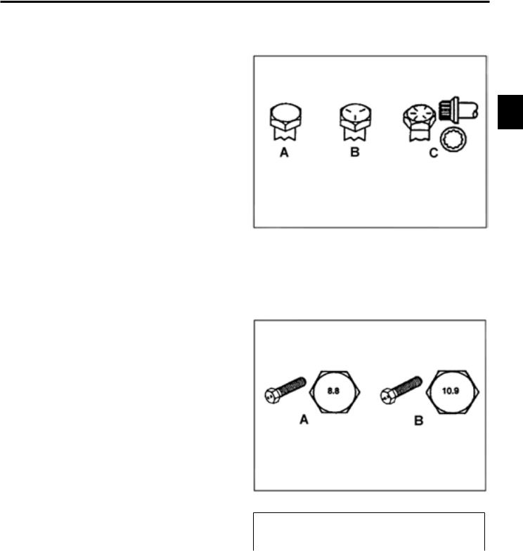
Fastener Identification
2
|
. |
|
|
||
Inch Series Bolts and Screws |
||
|
|
|
(A) Grade 1 & 2 |
|
(C) Grade 8 |
(B) Grade 5 |
|
|
|
|
|
.
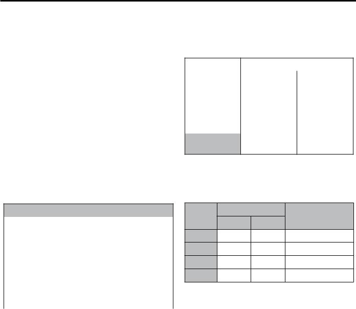
Metric Bolts and Screws
(A) Class 8.8 |
(B) Class 10.9 |
|
|
Toro GrandStand Service Manual |
2-1 |

SPECIFICATIONS
Standard Torque for Dry, Zinc Plated & Steel Fasteners (Inch Series)
|
|
|
Grade 1, 5, & |
SAE Grade 1 Bolts, Screws, |
SAE Grade 5 Bolts, Screws, |
SAE Grade 8 Bolts, Screws, |
||||||||||||
|
|
Thread Size |
8 with Thin |
Studs, & Sems with Regular |
Studs, & Sems with Regular |
Studs, & Sems with Regular |
||||||||||||
|
|
Height Nuts |
Height Nuts (SAE J995 |
Height Nuts (SAE J995 |
Height Nuts (SAE J995 |
|||||||||||||
|
|
|
||||||||||||||||
|
|
|
|
|
Grade 2 or Stronger Nuts) |
Grade 2 or Stronger Nuts) |
Grade 2 or Stronger Nuts) |
|||||||||||
2 |
|
|
|
|
||||||||||||||
|
|
In-lb |
|
In-lb |
|
N-cm |
|
In-lb |
|
|
N-cm |
|
In-lb |
|
N-cm |
|
||
|
|
|
|
|
|
|
|
|
|
|
|
|
|
|
|
|
||
|
# 6 - 32 UNC |
10 |
± 2 |
13 |
± 2 |
147 |
± 23 |
15 |
± |
2 |
169 |
± 23 |
23 |
± 2 |
260 |
± 34 |
||
|
||||||||||||||||||
|
|
# 6 - 40 UNF |
17 |
± |
2 |
190 |
± 20 |
25 |
± 2 |
280 |
± 20 |
|||||||
|
|
|
|
|
|
|
|
|||||||||||
|
|
# 8 - 32 UNC |
13 |
± 2 |
25 |
± 5 |
282 |
± 30 |
29 |
± |
3 |
330 |
± 30 |
41 |
± 4 |
460 |
± 45 |
|
|
|
# 8 - 36 UNF |
31 ± 3 |
350 |
± 30 |
43 |
± 4 |
31 ± 3 |
||||||||||
|
|
|
|
|
|
|
|
|||||||||||
|
|
# 10 - 24 UNC |
18 |
± 2 |
30 |
± 5 |
339 |
± 56 |
42 |
± 4 |
475 |
± 45 |
60 |
± 6 |
674 |
± 70 |
||
|
|
#10 - 32 UNF |
48 |
± 4 |
540 |
± 45 |
68 |
± 6 |
765 |
± 70 |
||||||||
|
|
|
|
|
|
|
|
|||||||||||
|
|
1/4 - 20 UNC |
48 |
± 7 |
53 |
± 7 |
599 |
± 79 |
100 |
± 10 |
1125 ± 100 |
140 |
± 15 |
1580 |
± 170 |
|||
|
|
1/4 - 28 UNF |
53 |
± 7 |
65 ± 10 |
734 ± 113 |
115 ± 10 |
1300 |
± 100 |
160 |
± 15 |
1800 |
± 170 |
|||||
|
|
5/16 - 18 UNC |
115 ± 15 |
105 |
± 15 |
1186 ± 169 |
200 |
± 25 |
2250 |
± 280 |
300 |
± 30 |
3390 |
± 340 |
||||
|
|
5/16 - 24 UNF |
138 |
± 17 |
128 |
± 17 |
1446 |
± 192 |
225 |
± 25 |
2540 |
± 280 |
325 |
± 30 |
3670 |
± 340 |
||
|
|
|
ft-lb |
ft-lb |
N-m |
ft-lb |
N-m |
ft-lb |
N-m |
|||||||||
|
|
3/8 - 16 UNC |
16 |
± 2 |
16 |
± 2 |
22 |
± 3 |
30 |
± 3 |
41 |
± 4 |
43 |
± 4 |
58 |
± 5 |
||
|
|
3/8 - 24 UNF |
17 |
± 2 |
18 |
± 2 |
24 |
± 3 |
35 |
± 3 |
47 |
± 4 |
50 |
± 4 |
68 |
± 5 |
||
|
|
7/16 - 14 UNC |
27 |
± 3 |
27 |
± 3 |
37 |
± 4 |
50 |
± 5 |
68 |
± 7 |
70 |
± 7 |
68 |
± 9 |
||
|
|
7/16 - 20 UNF |
29 |
± 3 |
29 |
± 3 |
39 |
± 4 |
55 |
± 5 |
75 |
± 7 |
77 |
± 7 |
104 ± 9 |
|||
|
|
1/2 - 13 UNC |
30 |
± 3 |
48 |
± 7 |
65 |
± 9 |
75 |
± 8 |
102 ± 11 |
105 |
± 10 |
142 |
± 14 |
|||
|
|
1/2 - 20 UNF |
32 |
± 3 |
53 |
± 7 |
72 |
± 9 |
85 |
± 8 |
115 |
± 11 |
120 |
± 10 |
163 |
± 14 |
||
|
|
5/8 - 11 UNC |
65 ± 10 |
88 ± 12 |
119 |
± 16 |
150 |
± 15 |
203 |
± 20 |
210 |
± 20 |
285 |
± 27 |
||||
|
|
5/8 - 18 UNF |
75 ± 10 |
95 ± 15 |
129 |
± 20 |
170 |
± 15 |
230 |
± 20 |
240 |
± 20 |
325 |
± 27 |
||||
|
|
3/4 - 10 UNC |
93 ± 12 |
140 |
± 20 |
190 |
± 27 |
265 |
± 25 |
359 |
± 34 |
374 |
± 35 |
508 |
± 47 |
|||
|
|
3/4 - 16 UNF |
115 ± 15 |
165 |
± 25 |
224 |
± 34 |
300 |
± 25 |
407 |
± 34 |
420 |
± 35 |
569 |
± 47 |
|||
|
|
7/8 - 9 UNC |
140 |
± 20 |
225 |
± 25 |
305 |
± 34 |
430 |
± 45 |
583 |
± 61 |
600 |
± 60 |
813 |
± 81 |
||
|
|
7/8 - 14 UNF |
155 |
± 25 |
260 |
± 30 |
353 |
± 41 |
475 |
± 45 |
644 |
± 61 |
660 |
± 60 |
895 |
± 81 |
||
|
|
|
|
|
|
|
|
|
|
|
|
|
|
|
|
|
|
|
Note: Reduce torque values listed in the table above by 25% for lubricated fasteners. Lubricated fasteners are defined as threads coated with a lubricant such as oil, graphite, or thread sealant such as Loctite.
Note: Torque values may have to be reduced when installing fasteners into threaded aluminum or brass. The specific torque value should be determined based on the fastener size, the aluminum or base material strength, length of thread engagement, etc.
Note: The nominal torque values listed above for Grade 5 and 8 fasteners are based on 75% of the minimum proof load specified in SAE J429. The tolerance is approximately ± 10% of the nominal torque value. Thin height nuts include jam nuts.
2-2 |
Toro GrandStand Service Manual |

SPECIFICATIONS
Standard Torque for Dry, Zinc & Steel Fasteners (Metric Fasteners)
|
Class 8.8 Bolts, Screws, and Studs with |
Class 10.9 Bolts, Screws, and Studs with |
|
|
|||||||
Thread Size |
|
Regular Height Nuts |
|
Regular Height Nuts ( |
|
|
|||||
|
|
(Class 8 or Strong Nuts) |
|
Class 10 or Strong Nuts) |
|
|
|||||
M5 X 0.8 |
57 ± 5 in-lb |
644 ± 68 N-cm |
78 ± 8 in-lb |
881 ± 90 N-cm |
|
|
|||||
2 |
|||||||||||
M6 X 1.0 |
96 ± 10 in-lb |
1085 ± 113 N-cm |
133 ± 14 in-lb |
1503 ± 158 N-cm |
|
||||||
M8 X 1.25 |
19 |
± 2 ft-lb |
26 |
± 3 N-m |
28 |
± 3 ft-lb |
38 |
± 4 N-m |
|
||
|
|||||||||||
M10 X 1.5 |
38 |
± 4 ft-lb |
52 |
± 5 N-m |
54 |
± 6 ft-lb |
73 |
± 8 N-m |
|
|
|
M12 X 1.75 |
66 |
± 7 ft-lb |
90 ± 10 N-m |
93 ± 10 ft-lb |
126 |
± 14 N-m |
|
|
|||
M16 X 2.0 |
166 |
± 15 ft-lb |
225 |
± 23 N-m |
229 |
± 23 ft-lb |
310 |
± 31 N-m |
|
|
|
M20 X 2.5 |
325 |
± 33 ft-lb |
440 |
± 45 N-m |
450 |
± 36 ft-lb |
610 |
± 62 N-m |
|
|
|
|
|
|
|
|
|
|
|
|
|
|
|
Note: Reduce torque values listed in the table above by 25% for lubricated fasteners. Lubricated fasteners are defined as threads coated with a lubricant such as oil, graphite, or thread sealant such as Loctite.
Note: Torque values may have to be reduced when installing fasteners into threaded aluminum or brass. The specific torque value should be determined based on the fastener size, the aluminum or base material strength, length of thread engagement, etc.
Note: The nominal torque values listed above are based on 75% of the minimum proof load specified in SAE J1199. The tolerance is approximately ± 10% of the nominal torque value. Thin height nuts include jam nuts.
Toro GrandStand Service Manual |
2-3 |
SPECIFICATIONS
Other Torque Specifications
SAE Grade 8 Steel Set Screws
|
|
Thread Size |
Recommended Torque |
|
|
|
|
|
|
2 |
|
Square Head |
Hex Socket |
|
|
|
|||
|
|
|
|
|
|
1/4 - 20 UNC |
140 ± 20 in-lb |
73 ± 12 in-lb |
|
|
|
|
|
|
|
|
5/16 - 18 UNC |
215 ± 35 in-lb |
145 ± 20 in-lb |
|
|
|
|
|
|
|
3/8 - 16 UNC |
35 ± 10 ft-lb |
18 ± 3 ft-lb |
|
|
|
|
|
|
|
1/2 - 13 UNC |
75 ± 15 ft-lb |
50 ± 10 ft-lb |
|
|
|
|
|
Wheel Bolts and Lug Nuts
Thread Size |
Recommended Torque** |
||
|
|
|
|
7/16 - 20 UNF |
65 ± 10 ft-lb |
88 ± 14 N-m |
|
Grade 5 |
|||
|
|
||
|
|
|
|
1/2 - 20 UNF |
80 ± 10 ft-lb |
108 ± 14 N-m |
|
Grade 5 |
|||
|
|
||
|
|
|
|
M12 X 1.25 |
80 ± 10 ft-lb |
108 ± 14 N-m |
|
Class 8.8 |
|||
|
|
||
|
|
|
|
M12 X 1.5 |
80 ± 10 ft-lb |
108 ± 14 N-m |
|
Class 8.8 |
|||
|
|
||
** For steel wheels and non-lubricated fasteners.
Thread Cutting Screws
(Zinc Plated Steel)
Type 1, Type 23, or Type F
Thread Size |
Baseline Torque* |
|
|
No. 6 - 32 UNC |
20 ± 5 in-lb |
|
|
No. 8 - 32 UNC |
30 ± 5 in-lb |
|
|
No.10 - 24 UNC |
38 ± 7 in-lb |
|
|
1/4 - 20 UNC |
85 ± 15 in-lb |
|
|
5/16 - 18 UNC |
110 ± 20 in-lb |
|
|
3/8 - 16 UNC |
200 ± 100 in-lb |
|
|
Thread Cutting Screws
(Zinc Plated Steel)
Thread |
Threads per Inch |
Baseline Torque* |
||
|
|
|||
Size |
Type A |
Type B |
||
|
||||
|
|
|||
No. 6 |
18 |
20 |
20 ± 5 in-lb |
|
No. 8 |
15 |
18 |
30 ± 5 in-lb |
|
No. 10 |
12 |
16 |
38 ± 7 in-lb |
|
No. 12 |
11 |
14 |
85 ± 15 in-lb |
|
* Hole size, material strength, material thickness and finish must be considered when determining specific torque values. All torque values are based on nonlubricated fasteners.
Conversion Factors |
|
in-lb X 11.2985 = N-cm |
N-cm X - 0.08851 = in-lb |
ft-lb X 1.3558 = N-m |
N-cm X 0.73776 = ft-lb |
2-4 |
Toro GrandStand Service Manual |

SPECIFICATIONS
Equivalents & Conversions
Decimal & Millimeter Equivalents
Fractions |
Decimals |
mm |
Fractions |
|
Decimals |
mm |
|
|
|
2 |
|||||||
|
|
|
|
|
|
|
|
|
|
|
|
|
|
|
|
|
|
1/64 |
0.015625 |
0.397 |
|
33/64 |
0.515625 |
13.097 |
|
|
|
|
|
|
|
|
|
|
|
1/32 |
0.03125 |
0.794 |
16/32 |
|
0.53125 |
13.484 |
|
|
|
|
|
|
|
|
|
|
|
3/64 |
0.046875 |
1.191 |
|
35/64 |
0.546875 |
13.891 |
|
|
|
|
|
|
|
|
|
|
|
1/16 |
0.0625 |
1.588 |
9/16 |
|
0.5625 |
14.288 |
|
|
|
|
|
|
|
|
|
|
|
5/64 |
0.078125 |
1.984 |
|
37/64 |
0.578125 |
14.684 |
|
|
|
|
|
|
|
|
|
|
|
3/32 |
0.9375 |
2.381 |
19/32 |
|
0.59375 |
15.081 |
|
|
|
|
|
|
|
|
|
|
|
1/8 |
0.1250 |
3.175 |
5/8 |
|
0.6250 |
15.875 |
|
|
|
|
|
|
|
|
|
|
|
9/64 |
0.140625 |
3.572 |
|
41/64 |
0.640625 |
16.272 |
|
|
|
|
|
|
|
|
|
|
|
5/32 |
0.15625 |
3.969 |
21/32 |
|
0.65625 |
16.669 |
|
|
|
|
|
|
|
|
|
|
|
11/64 |
0.171875 |
4.366 |
|
43/64 |
0.671875 |
17.066 |
|
|
|
|
|
|
|
|
|
|
|
3/16 |
0.1875 |
4.762 |
11/16 |
|
0.6875 |
17.462 |
|
|
|
|
|
|
|
|
|
|
|
13/64 |
0.203125 |
5.159 |
|
45/64 |
0.703125 |
17.859 |
|
|
|
|
|
|
|
|
|
|
|
7/32 |
0.21875 |
5.556 |
23/32 |
|
0.71875 |
18.256 |
|
|
|
|
|
|
|
|
|
|
|
15/64 |
0.234375 |
5.953 |
|
47/64 |
0.734375 |
18.653 |
|
|
|
|
|
|
|
|
|
|
|
1/4 |
0.2500 |
6.350 |
3/4 |
|
0.7500 |
19.050 |
|
|
|
|
|
|
|
|
|
|
|
17/64 |
0.265625 |
6.747 |
|
49/64 |
0.765625 |
19.447 |
|
|
|
|
|
|
|
|
|
|
|
9/32 |
0.28125 |
7.144 |
25/32 |
|
0.78125 |
19.844 |
|
|
|
|
|
|
|
|
|
|
|
19/64 |
0.296875 |
7.541 |
|
51/64 |
0.796875 |
20.241 |
|
|
|
|
|
|
|
|
|
|
|
5/16 |
0.3125 |
7.541 |
13/16 |
|
0.8125 |
20.638 |
|
|
|
|
|
|
|
|
|
|
|
21/64 |
0.328125 |
8.334 |
|
53/64 |
0.828125 |
21.034 |
|
|
|
|
|
|
|
|
|
|
|
11/32 |
0.34375 |
8.731 |
27/32 |
|
0.84375 |
21.431 |
|
|
|
|
|
|
|
|
|
|
|
23/64 |
0.359375 |
9.128 |
|
55/64 |
0.859375 |
21.828 |
|
|
|
|
|
|
|
|
|
|
|
3/8 |
0.3750 |
9.525 |
7/8 |
|
0.8750 |
22.225 |
|
|
|
|
|
|
|
|
|
|
|
25/64 |
0.390625 |
9.922 |
|
57/64 |
0.890625 |
22.622 |
|
|
|
|
|
|
|
|
|
|
|
13/32 |
0.40625 |
10.319 |
29/32 |
|
0.90625 |
23.019 |
|
|
|
|
|
|
|
|
|
|
|
27/64 |
0.421875 |
10.716 |
|
59/64 |
0.921875 |
23.416 |
|
|
|
|
|
|
|
|
|
|
|
7/16 |
0.4375 |
11.112 |
15/16 |
|
0.9375 |
23.812 |
|
|
|
|
|
|
|
|
|
|
|
29/64 |
0.453125 |
11.509 |
|
61/64 |
0.953125 |
24.209 |
|
|
|
|
|
|
|
|
|
|
|
15/32 |
0.46875 |
11.906 |
31/32 |
|
0.96875 |
24.606 |
|
|
|
|
|
|
|
|
|
|
|
31/64 |
0.484375 |
12.303 |
|
63/64 |
0.984375 |
25.003 |
|
|
|
|
|
|
|
|
|
|
|
1/2 |
0.5000 |
12.700 |
1 |
|
1.000 |
25.400 |
|
|
|
|
|
|
|
|
|
|
|
1 mm = 0.03937 in. |
|
|
0.001 in. = 0.0254 mm |
|
|
|
||
|
|
|
|
|
|
|
|
|
Toro GrandStand Service Manual |
2-5 |

SPECIFICATIONS
U.S. to Metric Conversions
|
|
|
To Convert |
Into |
Multiply By |
|
|
|
|
|
|
|
|
|
|
|
|
|
|
|
|
|
|
Miles |
Kilometers |
|
1.609 |
|
|
|
Yards |
Meters |
|
0.9144 |
2 |
|
|
|
|||
|
Linear |
Feet |
Meters |
|
0.3048 |
|
|
Feet |
Centimeters |
|
30.48 |
||
|
Measurement |
Inches |
Meters |
|
||
|
|
0.0254 |
||||
|
|
|
Inches |
Centimeters |
|
2.54 |
|
|
|
Inches |
Millimeters |
|
|
|
|
|
|
25.4 |
||
|
|
|
|
|
|
|
|
|
|
|
|
|
|
|
|
|
Square Miles |
Square Kilometers |
|
2.59 |
|
|
Area |
Square Feet |
Square Meters |
|
0.0929 |
|
|
Square Inches |
Square Centimeters |
|
6.452 |
|
|
|
|
|
|||
|
|
|
Acre |
Hectare |
|
0.4047 |
|
|
|
|
|
|
|
|
|
|
|
|
|
|
|
|
|
Cubic Yards |
Cubic Meters |
|
0.7646 |
|
|
Volume |
Cubic Feet |
Cubic Meters |
|
0.02832 |
|
|
|
Cubic Inches |
Cubic Centimeters |
|
16.39 |
|
|
|
|
|
|
|
|
|
|
Tons (Short) |
Metric Tons |
|
0.9078 |
|
|
Weight |
Pounds |
Kilograms |
|
0.4536 |
|
|
|
Ounces |
Grams |
|
28.3495 |
|
|
|
|
|
|
|
|
|
Pressure |
Pounds/Sq. In. |
Kilopascal |
|
6.895 |
|
|
|
|
|
|
|
|
|
|
Foot-pounds |
Newton-Meters |
|
1.356 |
|
|
Work |
Foot-pounds |
Kilogram-Meters |
|
0.1383 |
|
|
|
Inch-pounds |
Kilogram-Centimeters |
|
1.152144 |
|
|
|
|
|
|
|
|
|
Liquid Volume |
Quarts |
Liters |
|
0.9463 |
|
|
Gallons |
Liters |
|
3.785 |
|
|
|
|
|
|||
|
|
|
|
|
|
|
|
|
Liquid Flows |
Gallons/Minute |
Liters/Minute |
|
3.785 |
|
|
|
|
|
|
|
|
|
Temperature |
Fahrenheit |
Celsius |
1. |
Subtract 32° |
|
|
|
|
2. |
Multiply by 5/9 |
|
|
|
|
|
|
||
|
|
|
|
|
|
|
2-6 |
Toro GrandStand Service Manual |

SPECIFICATIONS
Domestic GrandStand Specifications
Engines: |
|
|
|
|
|
|
|
|
|
|
||
|
|
|
|
|
Output (Max. @ 3600 RPM’s) |
|
|
|
|
|||
|
|
18 hp |
|
19 hp |
20 hp |
23 hp |
24 hp |
26 hp |
|
|
||
|
|
(13.4kW) |
(14.2kW) |
(14.9kW) |
(17.2kW) |
(17.9kW) |
(19.4kW) |
|
|
|||
|
|
2 |
||||||||||
Make |
|
Kawasaki |
Kawasaki |
Kawasaki |
Kawasaki |
Kawasaki |
Kawasaki |
|
||||
Model |
|
FS541V |
FH580V |
FS600V |
FH680V |
FS691V |
FS730V |
|
||||
|
||||||||||||
Hi-Idle |
|
3600 ± 100 |
3600 ± 100 |
3600 ± 100 |
3600 ± 100 |
3600 ± 100 |
3600 ± 100 |
|
|
|||
|
|
RPM |
|
RPM |
RPM |
RPM |
RPM |
RPM |
|
|
||
Starter |
|
Electric |
|
Electric |
Electric |
Electric |
Electric |
Electric |
|
|
||
Spark Plug |
|
NGK BPR4ES |
Champion |
NGK BPR4ES |
NGK BPR4ES |
NGK BPR4ES |
NGK BPR4ES |
|
|
|||
|
|
|
|
RCJ8Y |
|
|
|
|
|
|
|
|
Oil |
|
SAE 10w-30/ |
SAE 10w-30/ |
SAE 10w-30/ |
SAE 10w-30/ |
SAE 10w-30/ |
SAE 10w-30/ |
|
|
|||
|
|
SAE10w-40 |
SAE10w-40 |
SAE10w-40 |
SAE10w-40 |
SAE10w-40 |
SAE10w-40 |
|
|
|||
Oil Capacity |
|
2.1 Qt. (2.0 L) |
3.8 Pint (1.8L) |
2.1 Qt. (2.0 L) |
2.0 Qt. (1.9 L) |
2.2 Qt. (2.2 L) |
2.2 Qt. (2.2 L) |
|
|
|||
CARB |
|
79534 / 79536 |
79558 / 79559 |
|
No |
Yes |
79548 / 79549 |
79551 |
|
|
||
Fuel System: |
|
|
|
|
|
|
|
|
|
|
||
7 or 12 Gallons (26.5 or 45.4L) fuel tank capacity |
|
|
|
|
|
|
|
|||||
Traction Drives: |
|
|
|
|
|
|
|
|
|
|
||
Traction Control: |
|
Toro “Split-Handle” Control Levers |
|
|
|
|
||||||
Hydraulic Pump: |
|
Two Hydro-Gear Model PG 10cc (Same Part # / No Left & Right) |
|
|
||||||||
Hydraulic Wheel Motor: |
|
Two Parker TEO-195 |
|
|
|
|
|
|||||
Hydraulic Oil Filter: |
|
25 Micron Automotive Spin-On Type |
|
|
|
|
||||||
Hydraulic Fluid: |
|
|
Toro Hypr-Oil or Equivalent Synthetic 15w50 |
|
|
|
|
|||||
Hydraulic Fluid Capacity: |
|
2.1 quarts (1.9 liters) |
|
|
|
|
|
|||||
Parking Brake: |
|
|
Standard Equipment |
|
|
|
|
|
||||
Ground Speed: (Hydro-MPH) |
|
Variable, 3 (5 kph) to 8 (13 kph) MPH Fwd / 0 to 3 (5 kph) MPH Rev |
|
|
||||||||
Hourmeter with Service Indicator: |
Standard Equipment |
|
|
|
|
|
||||||
Wheels & Tires: |
|
|
|
|
|
|
|
|
|
|
||
Front Castors Tires: |
|
11”x4” - 5”, 4 ply, Smooth Tread, Semi Pneumatic |
|
|
|
|||||||
Front Castors Fork: |
|
Heavy-Duty Design with 1” (25.4mm) Diameter Pivot Shaft |
|
|
|
|||||||
Rear Traction Tires: |
|
20”x10”-8”, 4 ply with Turf Traction Tread |
|
|
|
|
||||||
Mower Drive:
Toro GrandStand Service Manual |
2-7 |

SPECIFICATIONS
Domestic GrandStand Specifications cont.
|
|
Mower Engagement: |
|
Engine Mounted Electric Clutch |
|
|
|
||
|
|
Clutch Adjustment: |
|
Periodic Air Gap Adjustment Required - .018” + .003” (0.45 + 0.0762 mm) |
|||||
|
|
PTO Drive Belt: |
|
|
HB Section w/Aramid (Kevlar) Cords and Dry Clutching Envelope |
|
|||
2 |
|
|
|
|
|
|
|||
|
PTO Idler: |
|
|
Spring Loaded Pivot Hub w/Friction Washer Dampening |
|
||||
|
Deck Drive Belt: |
|
HA Section with Aramid (Kevlar) Cords and Standard (Non-Clutching) Envelope |
||||||
|
|
Deck Drive Idler: |
|
Spring Loaded Pivot Hub w/Friction Washer Dampening |
|
||||
|
|
Mower Decks: |
|
|
|
|
|
|
|
|
|
HOC Range: |
|
|
1” to 5” in 1/4” increments (25.4mm to 127mm in 6.3mm increments) |
||||
|
|
Blades: |
|
|
Three .250” (6.3mm) Thick Heat Treated Steel Blades |
|
|||
|
|
Spindles: |
|
|
Machined Steel 1.00” (25mm) Diameter Shaft |
|
|
||
|
|
Spindle Housing: |
|
Ductile Cast Iron, 9-3/8” (24cm) Diameter Mounted with Six Bolts |
|
||||
|
|
Bearings: |
|
|
Greasable Ball Bearings with Grease Fitting for Lubrication |
|
|||
|
|
Construction: |
|
|
7 gauge (.179” / 4.5mm) Steel Welded Construction |
|
|||
|
|
Blade Tip Speed: (Domestic) |
|
48” - 18,750 ft/m calculated @ 3600 engine RPM |
|
|
|||
|
|
|
|
|
52” - 18,750 ft/m calculated @ 3600 engine RPM |
|
|
||
|
|
|
|
|
60” - 18,750 ft/m calculated @ 3600 engine RPM |
|
|
||
|
|
Skid Plate: |
|
|
Standard |
|
|
|
|
|
|
Adjustable Discharge Baffle: |
|
Standard |
|
|
|
|
|
|
|
Rubber Discharge Chute: |
|
Standard |
|
|
|
|
|
|
|
Unit Dimensions: |
|
|
|
|
|
|
|
|
|
Deck |
|
|
Width |
Width |
Length |
Length |
|
|
|
Height |
|
Deflector |
Deflector |
Platform |
Weight* |
||
|
|
Width |
|
Platform Up |
|||||
|
|
|
|
Down |
Raised |
Down |
|
||
|
|
|
|
|
|
|
|||
|
|
48” (122cm) |
48” (122cm) |
63.5” (161cm) |
49.5” (126cm) |
74” (188cm) |
53” (135cm) |
887 lbs (400kg) |
|
|
|
52” (132cm) |
48” (122cm) |
67.5” (171cm) |
53.5” (135cm) |
74” (188cm) |
53” (135cm) |
900 lbs (408kg) |
|
|
|
60” (152cm) |
48” (122cm) |
75.5” (191cm) |
61.5” (156cm) |
74” (188cm) |
53” (135cm) |
925 lbs (419kg) |
|
* Estimated operating weight
2-8 |
Toro GrandStand Service Manual |

|
|
|
|
|
|
SPECIFICATIONS |
|
||||
International GrandStand Specifications |
|
|
|
|
|||||||
Engines: |
|
|
|
|
|
|
|
|
|
|
|
|
|
|
|
|
Output (Max. @ 3000 RPM’s) |
|
|
|
|
||
|
|
19 hp (14.2 kW) |
|
20 hp (17.2 kW) |
|
23 hp (17.2 kW) |
|
|
2 |
||
Make |
|
Kawasaki |
|
Kawasaki |
|
Kawasaki |
|
|
|
||
Model |
|
FH580V |
|
|
FS600V |
|
FH680V |
|
|
|
|
Hi-Idle |
|
2900 ± 100 RPM |
|
2900 ± 100 RPM |
|
2900 ± 100 RPM |
|
|
|
||
|
|
||||||||||
Starter |
|
Electric |
|
|
Electric |
|
Electric |
|
|
|
|
Spark Plug |
|
Champion RCJ8Y |
|
NGK BPR4ES |
|
NGK BPR4ES |
|
|
|
||
Oil |
SAE 10w-30 / SAE10w-40 |
|
SAE 10w-30 / SAE10w-40 |
|
SAE 10w-30 / SAE10w-40 |
|
|
|
|||
Oil Capacity |
|
1.8 L (3.8 pint) |
|
1.9 L (4.0 pint) |
|
1.9 L (4.0 pint) |
|
|
|
||
Fuel System: |
|
|
|
|
|
|
|
|
|
|
|
26.5 L (7 gal.) Fuel Tank Capacity |
|
|
|
|
|
|
|
|
|
||
Traction Drives: |
|
|
|
|
|
|
|
|
|
|
|
Traction Control: |
|
|
|
Toro Twin Lever Control Levers |
|
|
|
|
|||
Hydraulic Pump: |
|
|
|
Two Hydro-Gear Model PG 10cc (Same Part # / No Left & Right) |
|
|
|||||
Hydraulic Wheel Motor: |
|
Two Parker TEO-195 |
|
|
|
|
|||||
Hydraulic Oil Filter: |
|
|
25 Micron Automotive Spin-On Type |
|
|
|
|
||||
Hydraulic Fluid: |
|
|
|
Toro Hypr-Oil or Equivalent Synthetic 15w50 |
|
|
|||||
Hydraulic Fluid Capacity: |
|
1.9 L (2.1 quarts) |
|
|
|
|
|||||
Parking Brake: |
|
|
|
Standard Equipment |
|
|
|
|
|||
Ground Speed: |
|
|
|
Variable, 3 (5 kph) to 8 (13 kph) MPH Fwd / 0 to 3 (5 kph) MPH Rev |
|
|
|||||
Hourmeter with Service Indicator |
|
Standard Equipment |
|
|
|
|
|||||
Wheels and Tires: |
|
|
|
|
|
|
|
|
|
|
|
Front Castors Tires: |
|
|
11”x4” - 5”, 4 ply, Smooth Tread, Semi Pneumatic |
|
|
||||||
Front Castors Fork: |
|
|
Heavy-Duty Design with 25.4mm (1”) Diameter Pivot Shaft |
|
|
||||||
Rear Traction Tires: |
|
|
20”x10”-8”, 4 ply with Turf Traction Tread |
|
|
|
|
||||
Toro GrandStand Service Manual |
2-9 |
SPECIFICATIONS
International GrandStand Specifications cont.
|
|
Mower Drive: |
|
|
|
|
|
|
|
|
|
|
|
Mower Engagement: |
|
Engine Mounted Electric Clutch |
|
|
|
||||
|
|
Clutch Adjustment: |
|
Periodic Air Gap Adjustment Required - 0.45 ± 0.0762 mm (.018” ± .003”) |
|||||||
|
|
PTO Drive Belt: |
|
|
HB Section W/ Aramid (Kevlar) Cords and Dry Clutching Envelope |
||||||
2 |
|
||||||||||
|
PTO Idler: |
|
|
Spring Loaded Pivot Hub w/Friction Washer Dampening |
|
||||||
|
|
Deck Drive Belt: |
|
|
HA Section with Aramid (Kevlar) Cords and Standard (Non-Clutching) |
||||||
|
|
||||||||||
|
|
|
|
|
|
Envelope |
|
|
|
|
|
|
|
Deck Drive Idler: |
|
Spring Loaded Pivot Hub w/Friction Washer Dampening |
|
||||||
|
|
Mower Decks: |
|
|
|
|
|
|
|
|
|
|
|
HOC Range: |
|
|
25.4mm (1”) to 127mm (5”) in 6.3mm (1/4”) increments |
|
|||||
|
|
Blades: |
|
|
Three 6.3mm (.250”) Thick Heat Treated Steel Blades |
|
|||||
|
|
Spindles: |
|
|
Machined Steel 25.4mm (1”) Diameter Shaft |
|
|||||
|
|
Spindle Housing: |
|
Ductile Cast Iron, Mounted with Six Bolts |
|
|
|
||||
|
|
Bearings: |
|
|
Greasable Ball Bearings with Grease Fitting for Lubrication |
|
|||||
|
|
Construction: |
|
|
7 gauge (.179” / 4.5mm) Steel Welded Construction |
|
|||||
|
|
Blade Tip Speed: |
|
122cm (48”) - 18,750 ft/m calculated @ 3600 engine RPM |
|
||||||
|
|
|
|
|
|
132cm (52”) - 18,750 ft/m calculated @ 3600 engine RPM |
|
||||
|
|
Skid Plate: |
|
|
Standard |
|
|
|
|
||
|
|
Adjustable Discharge Baffle: |
|
Standard |
|
|
|
|
|||
|
|
Rubber Discharge Chute: |
|
Standard |
|
|
|
|
|||
|
|
Unit Dimensions: |
|
|
|
|
|
|
|
||
|
|
|
|
|
Width |
Width |
Length |
Length |
|
|
|
|
|
Deck Width |
|
Height |
Deflector |
Deflector |
Platform |
|
Weight* |
||
|
|
|
Platform Up |
|
|||||||
|
|
|
|
|
Down |
Raised |
Down |
|
|
||
|
|
|
|
|
|
|
|
||||
|
|
122cm (48”) |
|
122cm (48”) |
161cm (63.5”) |
126cm (49.5”) |
135cm (53”) |
188cm (74”) |
400 kg (881 lbs) |
||
|
|
132cm (52”) |
|
122cm (48”) |
171cm (67.5”) |
135cm (53”) |
135cm (53”) |
188cm (74”) |
408 kg (900 lbs) |
||
|
|
* Estimated operating weight |
|
|
|
|
|
|
|
||
2-10 |
Toro GrandStand Service Manual |
CHASSIS
Parking Brake Assembly
Replacement
Parking Brake Assembly Removal
1.Move the parking brake lever to the “OFF” position (Fig. 0001).
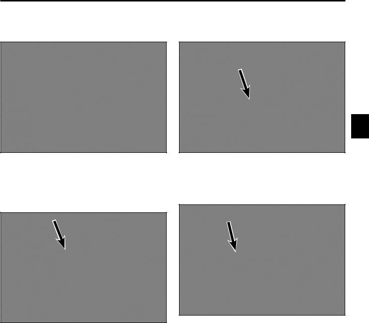
2.Remove the hairpin cotter and clevis pin securing the linkage yoke at the lower end of the brake rod to the brake assembly (Fig. 0002).
3
Fig. 0002 DSCN-0264a
|
|
|
3. Move the parking brake lever to the “ON” position |
|
|
||
Fig. 0001 |
IMG-1302a |
|
(Fig. 0003). |
|
|
|
|
|
|
|
|
Fig. 0003 |
IMG-1310a |
Toro GrandStand Service Manual |
3-1 |
CHASSIS
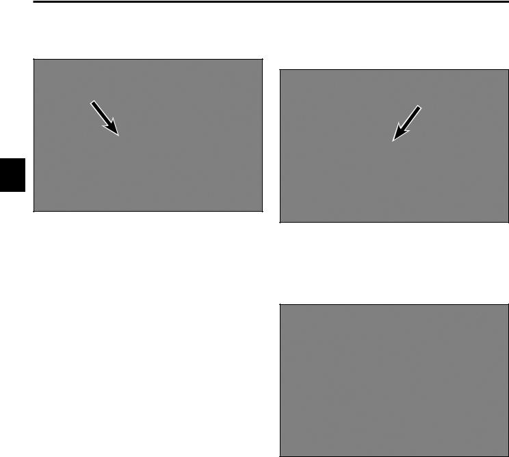
4.Remove the hairpin cotter from the top end of the parking brake rod. Slide the top end of the rod out of the handle (Fig. 0004).
5.Remove the hairpin cotter and clevis pin securing the top and bottom brake arms to the brake lever (Fig. 0006).
3
Fig. 0004 |
IMG-9347a |
Fig. 0006 |
DSCN-0268a |
Note: 2010 models use a nut to secure the upper end of the parking brake rod (Fig. 0005).
6.Disconnect the wire harness from the brake switch (Fig. 0007).
Fig. 0005 |
DSCN-0261a |
Fig. 0007 |
DSCN-0265a |
3-2 |
Toro GrandStand Service Manual |
CHASSIS
7.Remove the carriage bolt and nut securing the brake lever and brake switch plate to the control tower, then remove the brake lever and brake switch plate (Fig. 0008).
9.Remove the shoulder bolt, thick washer and nut securing the LH side of the brake assembly to the chassis, then remove the brake assembly (Fig. 0010).
3
Fig. 0008 |
DSCN-0255a |
Fig. 0010 |
IMG-1325a |
8.Remove the bolt and nut securing the RH side of the brake assembly and torsion spring assembly to the chassis (Fig. 0009).
Fig. 0009 |
IMG-1324a |
Toro GrandStand Service Manual |
3-3 |
CHASSIS
Parking Brake Assembly Installation
1.Secure the LH side of the brake assembly to the chassis using the shoulder bolt, thick washer and nut (Fig. 0011).
3
Fig. 0011 |
IMG-1325a |
2.Place the small spacer onto the bolt that secures the RH side of the brake assembly (Fig. 0012).
3.Position the bolt and spacer through the chassis mount and brake assembly. The spacer must be nested in the chassis mount (Fig. 0013).
Fig. 0013 |
IMG-1332a |
4. Position the large spacer onto the bolt (Fig. 0014).
Fig. 0014 |
IMG-1334a |
Fig. 0012 |
IMG-1329a |
3-4 |
Toro GrandStand Service Manual |
CHASSIS
5.Position the torsion spring over the spacer and bolt. The straight end of the spring is secured by the chassis, the curved end hooks under the brake assembly (Fig. 0015).
Fig. 0015 |
IMG-1336a |
6.Secure the RH assembly using the washer and nut (Fig. 0016).
7.Position the carriage bolt through the RH side of the control tower (Fig. 0017).
3
Fig. 0017 |
IMG-1338a |
8.Position the switch plate onto the carriage bolt (Fig. 0018).
Note: The switch plate has a square hole that must be nested onto the square shank of the carriage bolt.
Fig. 0016 |
IMG-1324a |
Fig. 0018 |
IMG-1344a |
Toro GrandStand Service Manual |
3-5 |
CHASSIS
9.Position one of the large washers onto the carriage bolt (Fig. 0019).
11.Position the brake lever through the control panel and onto the shouldered spacer (Fig. 0021).
3
Fig. 0019 |
IMG-1348a |
Fig. 0021 |
IMG-1355a |
10.Position the shouldered spacer onto the carriage bolt (Fig. 0020).
12.Secure the brake lever assembly with the large washer and nut (Fig. 0022).
Fig. 0020 |
IMG-1351a |
Fig. 0022 |
DSCN-0255a |
3-6 |
Toro GrandStand Service Manual |
CHASSIS
13.Position the clevis pin through the bottom brake arm (Fig. 0023).
15.Position the top brake arm onto the clevis pin (Fig. 0025).
3
Fig. 0023 |
IMG-1365a |
Fig. 0025 |
DSCN-0259a |
14.Insert the clevis pin through the brake lever (Fig. 0024).
16. Install the hairpin cotter to the clevis pin (Fig. 0026).
Fig. 0026 |
DSCN-0268a |
Fig. 0024 |
IMG-1367a |
Toro GrandStand Service Manual |
3-7 |
CHASSIS
17.Plug the wire harness into the brake switch (Fig. 0027).
18.Feed the brake rod up through the fuel tank base and secure the upper end to the brake arm using a hairpin cotter (Fig. 0028).
3
Fig. 0027 |
DSCN-0265a |
Fig. 0028 |
IMG-9347a |
Note: 2010 models use a nut to secure the upper end of the parking brake rod (Fig. 0029).
Fig. 0029 |
DSCN-0261a |
3-8 |
Toro GrandStand Service Manual |
CHASSIS
19.Secure the yoke on the lower end of the brake rod to the brake assembly using a clevis pin and hairpin cotter (Fig. 0030).
21.If adjustment is needed, remove the clevis pin secur ing the yoke to the brake arm. Rotate the yoke to obtain the desired gap (Fig. 0032).
3
Fig. 0030 |
DSCN-0264a |
Fig. 0032 |
DSCN-0264a |
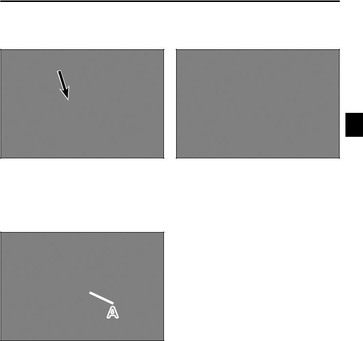
20.The brake assembly should contact the tires when there is approximately 3/4” (1.9cm) gap between the front edge of the control panel slot and the front edge of the brake lever (Fig. 0031).
 A
A
Fig. 0031 |
DSCN-0263a |
A. 3/4” (1.9cm)
Toro GrandStand Service Manual |
3-9 |
Loading...