


73550
Toro 73550, 73551, 73552, 73590, 74268 Service Manual
...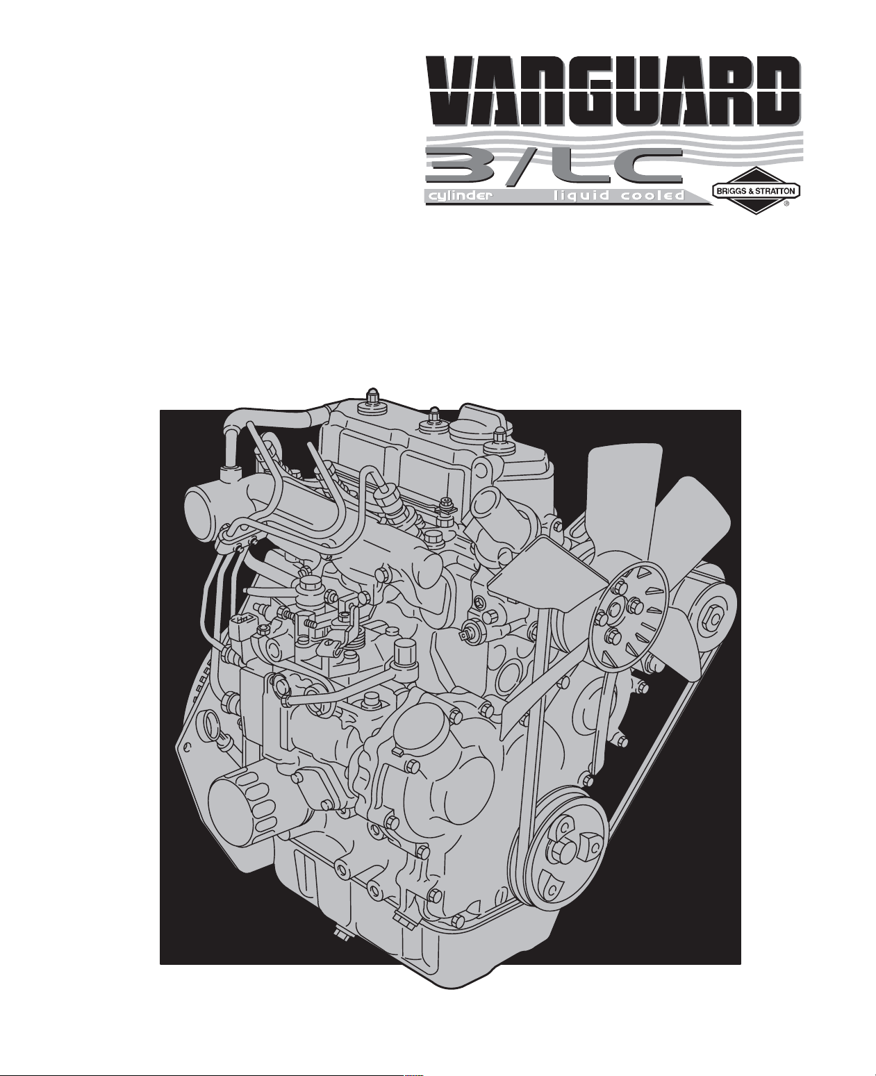
FORM MS-1055-5/02 2002 BRIGGS & STRATTON DAIHATSU LLC PRINTED IN U.S.A.
REPAIR MANUAL
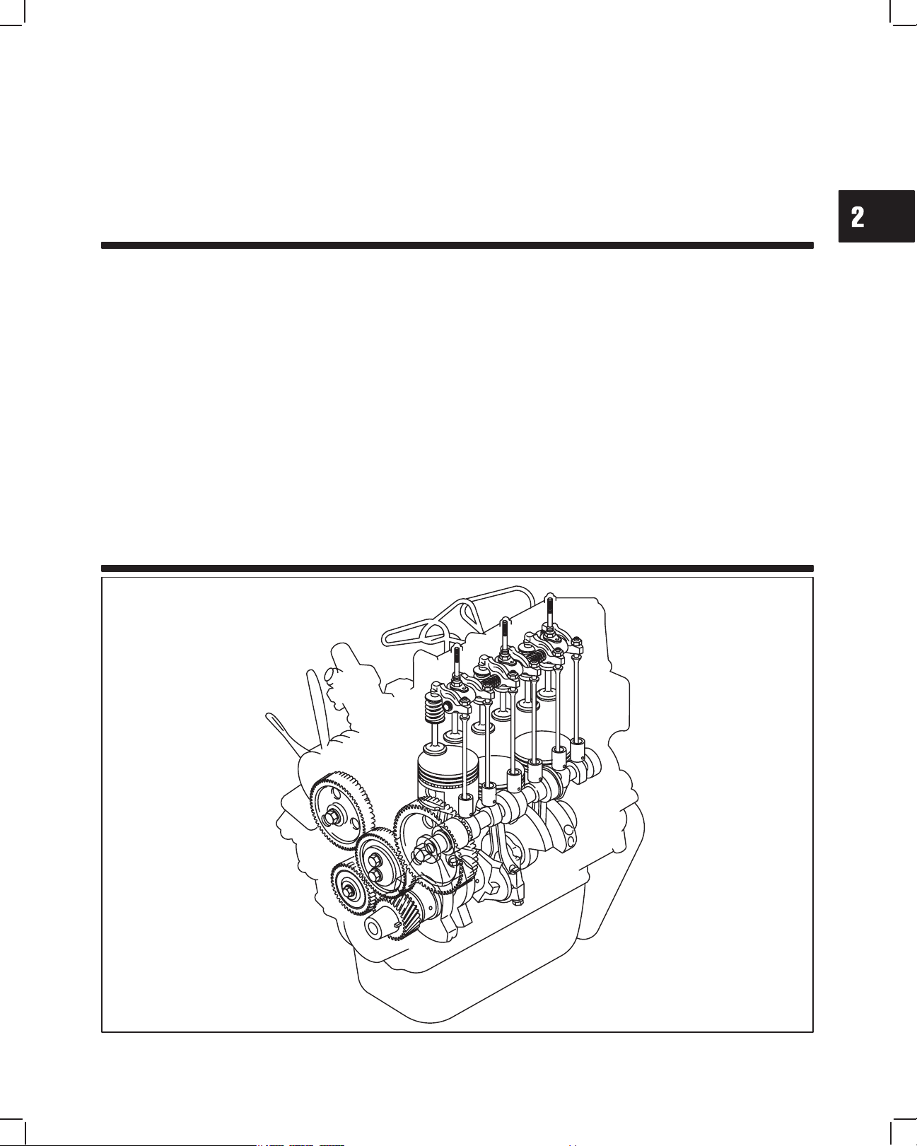
For 3 Cylinder LiquidĆCooled Diesel Engines

1
1
MAY 2002
Section 1
General Information
BRIGGS & STRATTON DAIHATSU 3 CYLINDER
LIQUID-COOLED DIESEL ENGINE REPAIR MANUAL (MS-1055)
Section Contents
Page
ENGINE IDENTIFICATION 1. . . . . . . . . . . . . . . . . . . . . . . . . . . . . . . . . . . . . . . . . . . . . . . . . . . . . . . . . . . . . . . . . . . . . . . .
IN THE INTEREST OF SAFETY 2. . . . . . . . . . . . . . . . . . . . . . . . . . . . . . . . . . . . . . . . . . . . . . . . . . . . . . . . . . . . . . . . . . . .
ENGINE VIEWS 3. . . . . . . . . . . . . . . . . . . . . . . . . . . . . . . . . . . . . . . . . . . . . . . . . . . . . . . . . . . . . . . . . . . . . . . . . . . . . . . . . .
ENGINE SPECIFICATIONS AND DATA 4. . . . . . . . . . . . . . . . . . . . . . . . . . . . . . . . . . . . . . . . . . . . . . . . . . . . . . . . . . . . .
FASTENER SPECIFICATIONS 9. . . . . . . . . . . . . . . . . . . . . . . . . . . . . . . . . . . . . . . . . . . . . . . . . . . . . . . . . . . . . . . . . . . .
BRIGGS & STRATTON NUMERICAL NUMBER SYSTEM 10. . . . . . . . . . . . . . . . . . . . . . . . . . . . . . . . . . . . . . . . . . . . .
MAINTENANCE SCHEDULE 11. . . . . . . . . . . . . . . . . . . . . . . . . . . . . . . . . . . . . . . . . . . . . . . . . . . . . . . . . . . . . . . . . . . . .
ENGINE IDENTIFICATION NUMBERS
The engine model and type number are located on the vale cover, Fig. 1. The serial number is stamped into the right
side of the cylinder block, behind the intake manifold, Fig. 2.
Fig. 1 – Engine Model And Type Number
MODEL AND
TYPE NO.
Fig. 2 – Engine Serial Number
SERIAL NO.
1
2
GENERAL INFORMATION
IN THE INTEREST OF SAFETY
This safety alert symbol indicates that this
message involves personal safety. Signal
words danger, warning and caution indicate
hazard degree. Death, personal injury and/OR
property damage may occur unless instruc-
tions are followed carefully.
WARNING: DO NOT
1. DO NOT run engine in an enclosed area. Exhaust
gases contain carbon monoxide, an odorless and
deadly poison.
2. DO NOT place hands or feet near moving or
rotating parts. Keep all guards in place.
3. DO NOT place hands or feet near electric cooling
fan (if equipped). Fan may start suddenly, de-
pending on coolant temperature.
4. DO NOT store, spill, or use diesel fuel near an
open flame, or devices such as a stove, furnace,
or water heater which use a pilot light or devices
which can create a spark.
5. DO NOT refuel indoors where area is not well
ventilated. Outdoor refueling is preferred.
6. DO NOT fill fuel tank while engine is running. Allow
engine to cool for 2 minutes before refueling.
Store fuel in approved, correct color safety
containers.
7. DO NOT remove fuel tank cap while engine is
running.
8. DO NOT operate engine when smell of fuel is
present or other explosive conditions exist.
9. DO NOT operate engine if diesel fuel is spilled.
Move machine away from the spill and avoid
creating any ignition until the spill has been
wiped up.
10. DO NOT smoke when filling fuel tank.
11. DO NOT tamper with maximum speed set screw
or full load set screw of the injector pump which
may increase the governed engine speed.
12. DO NOT tamper with the engine speed selected
by the original equipment manufacturer.
13. DO NOT operate engine with a damaged muffler
or without muffler. Inspect periodically and
replace, if necessary. If engine is equipped with
muffler deflector(s), inspect periodically and
replace, if necessary, with correct deflector(s).
14. DO NOT operate engine with an accumulation of
grass, leaves, dirt or other combustible material in
the muffler area.
15. DO NOT use this engine on any forest covered,
brush covered, or grass covered unimproved land
unless a spark arrester is installed on the muffler.
The arrester must be maintained in effective
working order by the operator. In the State of
California the above is required by law (Section
4442 of the California Public Resources Code).
Other states may have similar laws. Federal laws
apply on federal lands.
16. DO NOT touch hot muffler(s) or cylinder(s)
because contact may cause burns.
17. DO NOT remove the radiator cap while the engine
is hot. To avoid scalding from hot coolant or steam
blowing out of the radiator, use extreme care when
removing the radiator cap. If possible, wait for
engine to cool. If not possible, wrap a thick rag
around cap while removing. To release pressure,
slowly turn cap counter clockwise to the first stop.
When all pressure has been released, press down
on cap and continue turning.
18. DO NOT start or run engine with air cleaner or air
cleaner cover removed.
WARNING: DO
1. ALWAYS DO disconnect the negative wire from
the battery terminal when servicing the engine or
equipment, TO PREVENT ACCIDENTAL
STARTING.
2. ALWAYS DO disconnect fuel shut off solenoid wire
from injection pump before checking compression,
TO PREVENT ACCIDENTAL STARTING.
3. DO wear eye protection when operating or
repairing equipment.
4. DO keep governor parts free of grass and other
debris which can affect engine speed.
5. DO examine muffler(s) periodically to be sure it is
functioning effectively. A worn or leaking
muffler(s) should be repaired or replaced as
necessary.
6. DO check fuel lines and fittings frequently for
cracks or leaks. Replace if necessary.
CAUTION:
DO use clean fresh diesel fuel with a minimum of 40
cetane.
DO NOT use kerosene. The injection pump requires
diesel fuel for lubrication. Damage to the injection
pump and/or engine may result if kerosene is used.
NOTE: Use Original Briggs & Stratton-Daihatsu
Service Replacement Parts when
servicing your engine. Authorized Briggs
& Stratton-Daihatsu Service Centers
carry a stock of such parts. The use of
Briggs & Stratton-Daihatsu parts
preserves the original design of your
engine. Imitation replacement parts may
not fit or function as original Briggs &
Stratton-Daihatsu parts and can expose
the operator to potential personal injury.
Contact any Authorized Briggs &
Stratton-Daihatsu Service Center for
Original Briggs & Stratton-Daihatsu
Replacement Parts.
1
3
GENERAL INFORMATION
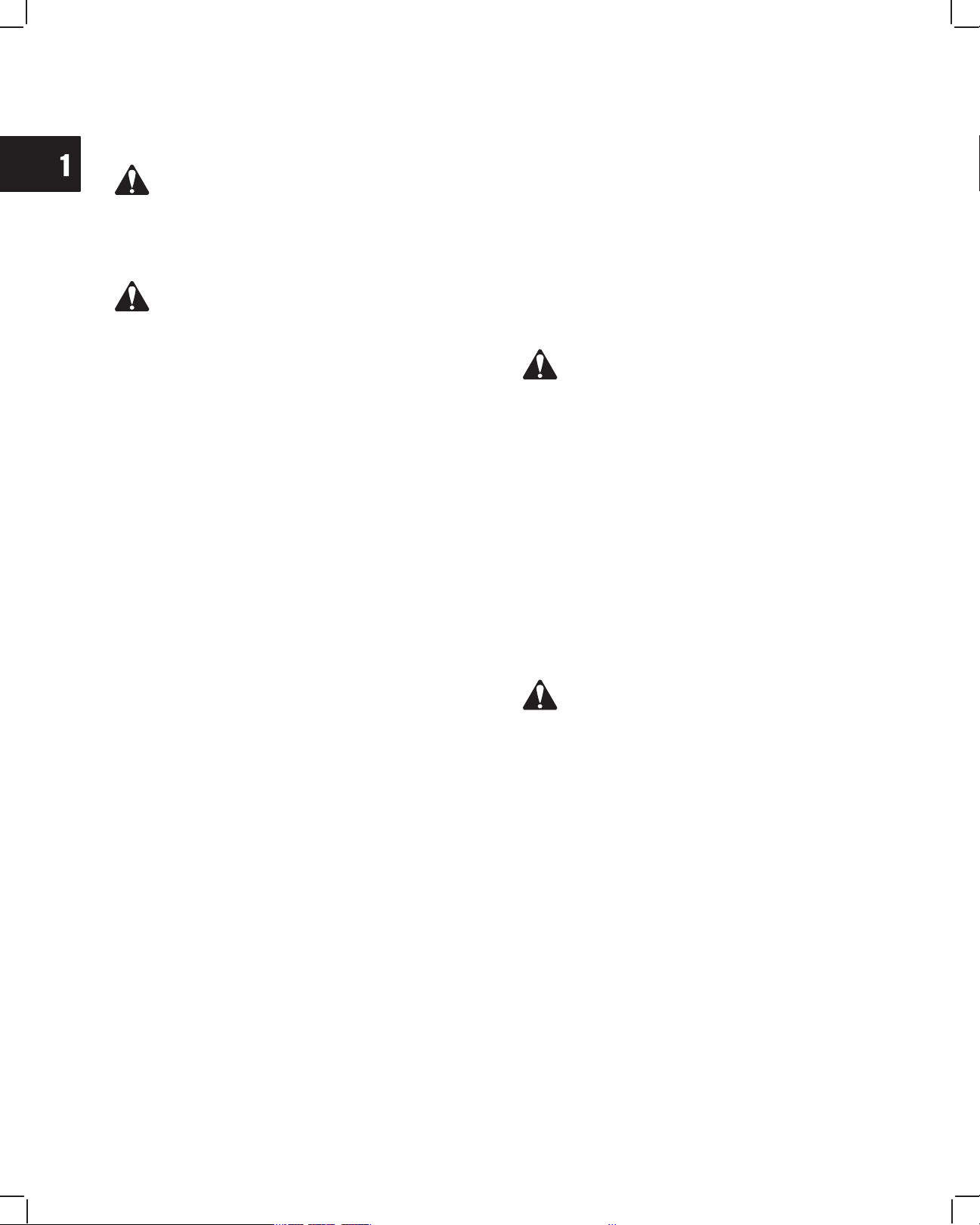
ENGINE VIEWS
1. Thermostat
2. Oil filler cap
3. Electric starter
4. Oil pan
5. Alternator
2
3
5
4
Diesel
1
11
6. Injector nozzle
7. Glow plug
8. Oil drains
9. Oil filter
10. Dipstick
11. Injector pump
12. Engine Date code
xxxxxxxx
13. Engine Model & Type number
xxxxxx xxxx-xx
7
10
13
9
6
8
12
1. Thermostat
2. Oil filler cap
3. Turbocharger
4. Electric starter
5. Alternator
6. Oil pan
Turbo-charged
Diesel
7. Injector nozzle
8. Glow plug
9. Oil drains
10. Oil cooler
(if equipped)
11. Oil filter
12. Dipstick
13. Injector pump
14. Engine Date code
xxxxxxxx
15. Engine Model & Type number
xxxxxx xxxx-xx
1
4
GENERAL INFORMATION
ENGINE SPECIFICATIONS
Model 432447 522447
582447
@58A447
@588447
Type Diesel, 4-cycle, 3 cylinder, in-line, liquid cooled
Valve mechanism OHV, gear driven
Bore x stroke mm (in)
68 x 64
(2.680 x 2.520)
68 x 78
(2.680 x 3.070)
72 x 78
(2.834 x 3.070)
Piston displacement cc (cu in) 697 (42.5) 850 (52.0) 952 (58.1)
Firing order 1-2-3 (front, center, back)
Compression ratio 25.0:1 24.4:1
24.0:1
@ 24.8:1
Compression pressure (normal)
@
300 RPM Bar
Engine at operating temperature – (psi)
glow plugs removed
33.0
(469)
32.0
(455)
34.0
(498)
@ 37
(526)
Compression pressure (minimum)
@
300 RPM Bar
Engine at operating temperature – (psi)
glow plugs removed
30.0
(425)
29.0
(412)
30.5
(433)
@ 27
(384)
Gross HP @ 3600 RPM 19.5 23.6
26.5
@ 28.0
Gross Torque @ 2400 RPM 32.5 40.0
44.1
@ 49.2
Dimensions (L x W x H) mm (in)
441.8 x 440.4 x
523.9
(17.4 x 17.34 x
20.6)
434.4 x 442.9 x
548.4
(17.1 x 17.44 x
21.59)
434.4 x 442.9
x 548.4
(17.1 x 17.44 x
21.59)
@ 434.4 x
447.5 x 559.0
(17.1 x 17.62 x
22.01)
Dry weight kg (lbs) 76 (168) 78 (172) 89 (196)

1
5
GENERAL INFORMATION
C
y
linder
Type Single piece casting
Cylinder
Head
Material Cast Iron
Combustion Chamber Swirl Type
Intake
45°
V
a
l
ve
seat
ang
l
e
Exhaust
45°
Opens 10° BTDC
°
V
a
l
ve
Valve timin
g
I
nta
k
e
Closes 45° ABDC
23
5°
Specifications
Valve timing
Opens 45° BBDC
°
E
x
h
aust
Closes 10° ATDC
23
5°
Intake mm (in) 0.20 (.008 in)
V
a
l
ve
c
l
earance
(
co
ld)
Exhaust mm (in) 0.20 (.008 in)
Cylinder
Cylinder block Mono-block, three cylinder, cast iron
Block &
Camshaft
Camshaft Carbon steel
Connecting rod Carbon steel
Piston Pin Bearing Machined – Piston pin, slip fit
Connecting
Crankpin
Bearing
Material aluminum alloy – replaceable insert
Rod & Piston
Piston Heat resistant aluminum alloy
Compression ring Two, chrome plated
Pi
ston
r
i
ng
Oil ring One, combination type, chrome plated
Crankshaft &
Crankshaft One piece cast iron
Crankshaft &
Crankshaft
Bearing
Crankshaft main
bearing
Material Replaceable insert – aluminum alloy
1
6
GENERAL INFORMATION
LUBRICATING SYSTEM
Lubricating Method Pressure lube
Type Trochoid
Oil Pump
Drive Gear drive
Oil Filter Type Full flow, paper
Oil Capacity 3.3 ltr (3.5 qt)
Oil Pump Relief Valve Opening Pressure 4.6 Bar (65 psi)
Lubrication Oil API SE/CD class or higher
COOLING SYSTEM
Cooling Method Liquid cooled, forced circulation
Coolant Capacity (engine only) Approximately 1.8 ltr (1.9 qt)
Cooling System Pressure 1.0-0.75 Bar (15-11 psi)
Pressure Cap Capacity 0.9 Bar (13 psi)
Type Centrifugal
Water Pump
Drive V-belt
Type Wax pellet with bypass
Thermostat
Specification 82° C (180° F)
Cooling Fan Drive V-belt
FUEL SYSTEM
Fuel Requirements Diesel fuel (Cetane number 40 or higher)
Type Bosch VE (distributor type)
Injector Pump
Injector Timing (Plunger stroke)
#1 Cyl. TDC
See Tables 1 & 2, Page 6
Nozzle Type Throttle type
Injector Nozzle
Injector pressure Bar (psi) 140 (1,991)
Idle Speed RPM See Table 3, Page 7
ELECTRICAL SYSTEM
Voltage 12V (negative ground)
Battery
Capacity 24 AH (28 AH cold)
Alternator 28 Volt AC output – Minimum
Charging
Regulator/rectifier 14 Amp DC output with charge indicator circuit
S
ys
t
em
Alternator {Optional} 40 Amp DC output – Internally regulated
Glow Plug Voltage/Current V/A 11 Volts / 9.5 Amps
Starter Voltage/Kilowatt V/K
Reduction gear type – 12 Volts / 1.0 kw
{12 Volts / 1.2 kw, optional}
1
7
GENERAL INFORMATION
Model/Type No. Timing Specification
0.93 ± .03 mm (.0365” ± .001”)
0.93 ± .03 mm (.0365” ± .001”)
0.93 ± .03 mm (.0365” ± .001”)
0.93 ± .03 mm (.0365” ± .001”)
0.93 ± .03 mm (.0365” ± .001”)
0.93 ± .03 mm (.0365” ± .001”)
0.93 ± .03 mm (.0365” ± .001”)
0.81 ± .03 mm (.032” ± .001”)
0.93 ± .03 mm (.0365” ± .001”)
0.81 ± .03 mm (.032” ± .001”)
432447-0150-E2
522447-0105-E2
522447-0106-E2
522447-0107-E2
522447-0108-E2
522447-0109-E2
582447-0105-E2
582447-0125-E2
582447-0130-E2
582447-0131-E2
TABLE 1
Injection Pump Timing
Engine Date Code Before 99010100
TABLE 2
Injection Pump Timing
Engine Date Code After 98123100
Model Series Timing Specification
0.90 ± .03 mm (.035” ± .001”)
0.90 ± .03 mm (.035” ± .001”)
0.81 ± .03 mm (.032” ± .001”)
0.90 ± .03 mm (.035” ± .001”)
432447 – All
522447 – All
582447 – All
58A447 – All
588447
1
8
TABLE 3
Engine Speed Specification Chart
Pump Mfg. Part No. ID Code Model & Type No. Idle Speed (rpm) Top No Load (rpm)
22100-87801 7U1 432447-0105-E2
1200±50 3850±50
22100-8713 7U2 432447-0205-E2
1200±50 3850±50
582447-0105-E2
582447-0205-E2
1200±50 3850±50
22100-87802 9U1
582447-0130-E2
582447-0230-E2
1200±50 3300±50
22100 87802
9U1
582447-0219-E2
582447-0222–E2
1600±50 3600±50
582447-0221-E2
1750±50 3600±50
582447-0225-E2
1050±50 3850±50
582447-0232-E2
1200±50 3400±50
582447-0125-E2
1850±50 3420±50
22100-87806 9U2
582447-0131-E2
582447-0231-E2
1700±50 3600±50
522447-0105-E2
1200±50 3850±50
22100
-
8
7
80
7
8U1
522447-0108-E2
1600±50 3350±50
522447-0106-E2
1850±50 3420±50
22100
-
8
7
809
8U2
522447-0109-E2
1850±50 3420±50
22100-87810 8U3 522447-0107-E2
1525±50 2775±50
22100-87815 8U4 522447-0107-E2
1540±50 2790±50
22100-87817 8U5 522447–0107–E2
1540±50 2790±50
22100-87811 9U4 58A447–0205–E2
1200±50 3850±50
22100-87818 9U5 588447–0205–E2
1200±50 3850±50
588447–0216–E2
1800±50 3600±50
588447–0230–E2
1600±50 3600±50
588447–0225–E2
1050±50 3850±50
NAME
PLATE
IDENTIFICATION
CODE
IDENTIFICATION CODE
7 : 700 cc
8 : 850 cc
9 : 950 cc
DESTINATION
U : USA
J : Japan
X : Except for
USA
SERIAL
NUMBER
INJECTOR PUMP IDENTIFICATION
1
9
GENERAL INFORMATION
Description Wrench/Socket Size Torque
Alternator Adjust. Bracket 12 mm 19.0 Nm (170 in. lbs.)
Alternator – 14 Amp (to bracket) 12 mm 19.0 Nm (170 in. lbs.)
Alternator – 40 Amp (to bracket) 12 mm 61.0 Nm (45 ft. lbs.)
Alternator Bracket (to block) 12 mm 19.0 Nm (170 in. lbs.)
Camshaft Gear 17 mm 41.0 Nm (30 ft. lbs.)
Camshaft Retainer 10 mm 8.0 Nm (70 in. lbs.)
Conn. Rod Nuts 12 mm 36.0 Nm (320 in. lbs.)
Crankshaft Pulley 19 mm 88.0 Nm (65 ft. lbs.)
Cyl. Head Bolts (8 mm dia.) 12 mm 34.0 Nm (25 ft. lbs.)
Cyl. Head Bolts (9 mm dia.) 13 mm 43.0 Nm (32 ft. lbs.)
Cyl. Head Bolts (10 mm dia.) 14 mm 68.0 Nm (50 ft. lbs.)
Exhaust Manifold 12 mm 19.0 Nm (170 in. lbs.)
Fan Pulley 10 mm 7.0 Nm (60 in. lbs.)
Flywheel 14 mm 47.0 Nm (35 ft. lbs.)
Fuel Delivery Lines 17 mm 25.0 Nm (220 in. lbs.)
Fuel Return Line 17 mm 27.0 Nm (20 ft. lbs.)
Glow Plug 12 mm Deep 17.0 Nm (150 in. lbs.)
Idler Gear 12 mm 25.0 Nm (220 in. lbs.)
Injector Pump (mounting) 12 mm 19.0 Nm (170 in. lbs.)
Injector Pump Drive Gear 19 mm 61.0 Nm (45 ft. lbs.)
Injector Pump Bracket 12 mm 19.0 Nm (170 in. lbs.)
Injector Nozzle 21 mm Deep 61.0 Nm (45 ft. lbs.)
Injector Pump Distributor Bolt 14 mm 17.0 Nm (150 in. lbs.)
Intake Manifold 10 mm 8.0 Nm (70 in. lbs.)
Main Bearing Screws 14 mm 58.0 Nm (43 ft. lbs.)
Oil Drain Plug 14 mm 25.0 Nm (220 in. lbs.)
Oil Pan 10 mm 8.0 Nm (70 in. lbs.)
Oil Pressure Relief Valve 19 mm 34.0 Nm (25 ft. lbs.)
Oil Pump Gear 12 mm 19.0 Nm (170 in. lbs.)
Oil Pump Pickup 10 mm 8.0 Nm (70 in. lbs.)
Rear Seal Support 10 mm 6.0 Nm (50 in. lbs.)
Rocker Arm Assy. 12 mm Deep 19.0 Nm (170 in. lbs.)
Rocker Arm Adjustment 10 mm 11.0 Nm (95 in. lbs.)
Starter 14 mm 40.0 Nm (30 ft. lbs.)
Starter Bracket 14 mm 34.0 Nm (25 ft. lbs.)
Starter Solenoid Phillips 9.0 Nm (80 in. lbs.)
Starter Motor Thru Bolts 10 mm 9.0 Nm (80 in. lbs.)
Timing Gear Case 10 mm 8.0 Nm (70 in. lbs.)
Timing Gear Cover
(3 different lengths)
10 mm 8.0 Nm (70 in. lbs.)
Valve Cover 10 mm 6.0 Nm (50 in. lbs.)
Water Pump 12 mm 19.0 Nm (170 in. lbs.)

1
10
GENERAL INFORMATION
BRIGGS & STRATTON DAIHATSU NUMERICAL NUMBER SYSTEM
All Briggs & Stratton Daihatsu engines have a unique numerical designation system. Each engine is identified by a
Model, Type and Code/Serial number. Example: Model Type Code/Serial
432447 0125 01 020521145
This chart explains the numerical model designation system. It is possible to determine most of the important mechani-
cal features of the engine by merely knowing the model number. Here is how it works.
FIRST DIGIT
AFTER DISPLACEMENT
SECOND DIGIT
AFTER DISPLACEMENT
THIRD DIGIT
AFTER DISPLACEMENT
FOURTH DIGIT
AFTER DISPLACEMENT
CUBIC INCH
DISPLACEMENT
BASIC
DESIGN SERIES
CRANKSHAFT,
CARBURETOR,
GOVERNOR
PTO BEARING,
REDUCTION GEAR,
AUXILIARY DRIVE,
LUBRICATION TYPE OF STARTER
ă6
ă8
ă9
10
11
12
13
16
17
18
19
22
23
24
25
26
28
29
30
32
35
38
40
42
43
44
46
52
58
0 - Gas-Mechanical
1 - Natural Gas-Mechanical
2 - Diesel-Mechanical
3 - Gas-Electronic
4 - Natural Gas-Electronic
5 - Diesel-Electronic
6
7
8 - Diesel - Turbo
9
A - Diesel Turbo
B to Z
0 - Horizontal Shaft
Diesel Electronic or
Mechanical Governor
1 - Horizontal Shaft
VacuĆJet Carburetor
Pneumatic Governor
2 - Horizontal Shaft
PulsaĆJet Carburetor
Pneumatic or Mechanical
Governor
3 - Horizontal Shaft
FloĆJet Carburetor
Pneumatic Governor
4 - Horizontal Shaft
FloĆJet Carburetor
Electronic or
Mechanical Governor
5 - Vertical Shaft
VacuĆJet Carburetor
Pneumatic or Mechanical
Governor
6 - Vertical Shaft
7 - Vertical Shaft
FloĆJet Carburetor
Pneumatic or Mechanical
Governor
8 - Vertical Shaft
FloĆJet Carburetor
Mechanical Governor
9 - Vertical Shaft
PulsaĆJet Carburetor
Pneumatic or Mechanical
Governor
0 - Plain Bearing/DU
NonĆFlange Mount
1 - Plain Bearing
Flange Mounting
2 - Sleeve Bearing
Flange Mounting
Splash Lube
3 - Ball Bearing
Flange Mounting
Splash Lube
4 - Flange Mounting
Pressure Lubrication on
Horizontal Shaft
5 - Plain Bearing
Gear Reduction
(6 to 1) CW Rotation
Flange Mounting
6 - Plain Bearing
Gear Reduction
(6 to 1) CCW Rotation
7 - Plain Bearing
Pressure Lubrication on
Vertical Shaft
8 - Plain Bearing
Auxiliary Drive (PTO)
Perpendicular to Crankshaft
9 - Plain Bearing
Auxiliary Drive
Parallel to Crankshaft
0 - Without Starter
1 - Rope Starter
2 - Rewind Starter
3 - Electric Starter Only
120 Volt Gear Drive
4 - Electric Starter/Generator
12 Volt Belt Drive
5 - Electric Starter Only
12 Volt Gear Drive
6 - Alternator Only
7 - Electric Starter
12 Volt Gear Drive
With Alternator
8 - Vertical Pull Starter or
Side Pull Starter
The type number identifies certain unique features such as the crankshaft or governor spring used on an engine.
The code/serial number identifies the assembly date of the engine and serial number. In some instances it is neces-
sary to know the code/serial number as well as the model and type number when performing adjustments, repairs or
ordering replacement parts for an engine. Here is how it works.
Example: 990521150
A. The first two digits, 02, indicate the calendar
year, 2002.
B. The second two digits, 05, indicate the calen-
dar month, May.
C. The third two digits, 21, indicate the calendar
month day.
D. The last three digits, 145, indicate the serial
number.
1
11
GENERAL INFORMATION
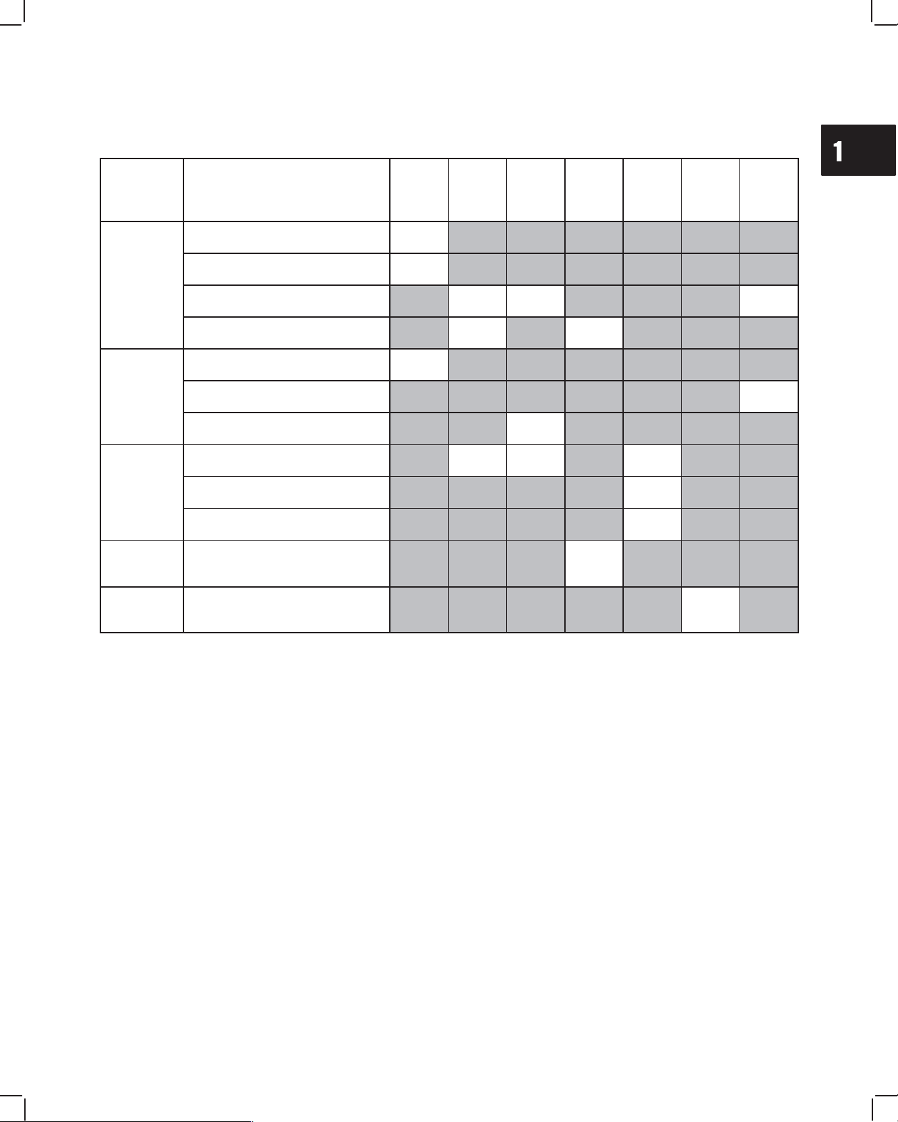
MAINTENANCE SCHEDULE
More frequent service is required when operating in adverse conditions (note 4 below).
System Maintenance Operation Daily
Every
50
hours
Every
100
hours
Every
200
hours
Every
600
hours
Every
800
hours
Yearly
Check oil level
D
Lubrication
Check for oil leaks
D
Lubrication
system
Change oil
D1 D2 D5
Change oil filter
D1 D2
Check coolant
D
Cooling
s
y
stem
Change coolant
D
system
Check fan belt
D
Service air cleaner
D1 D2, 4 D3, 4
Engine
Check cylinder head bolt torque
D
Check valve clearance
D
Electrical
system
Check battery electrolyte
D
Fuel
system
Change fuel filter element
D6
1 Perform first maintenance operation after 50 hours.
2 Then perform maintenance operation at this interval.
3 Replace after ever 600 hours of operation.
4 Service more often when operating under heavy load or in high temperatures.
5 Perform maintenance annually if operated less than 100 hours.
6 Follow manufacturer’s maintenance schedule if non-B&SD approved part is used.
2
1MAY 2002
Section Contents
Page
REMOVE CYLINDER HEAD 2. . . . . . . . . . . . . . . . . . . . . . . . . . . . . . . . . . . . . . . . . . . . . . . . . . . . . . . . . . . . . .
DISASSEMBLE CYLINDER HEAD 4. . . . . . . . . . . . . . . . . . . . . . . . . . . . . . . . . . . . . . . . . . . . . . . . . . . . . . . .
INSPECT AND REPAIR
Cylinder Head 5. . . . . . . . . . . . . . . . . . . . . . . . . . . . . . . . . . . . . . . . . . . . . . . . . . . . . . . . . . . . . . . . . . . . . .
Valve Guides 6. . . . . . . . . . . . . . . . . . . . . . . . . . . . . . . . . . . . . . . . . . . . . . . . . . . . . . . . . . . . . . . . . . . . . . .
Valves 7. . . . . . . . . . . . . . . . . . . . . . . . . . . . . . . . . . . . . . . . . . . . . . . . . . . . . . . . . . . . . . . . . . . . . . . . . . . . .
DISASSEMBLE ROCKER ARM SHAFT 8. . . . . . . . . . . . . . . . . . . . . . . . . . . . . . . . . . . . . . . . . . . . . . . . . . . .
ASSEMBLE ROCKER ARM SHAFT 9. . . . . . . . . . . . . . . . . . . . . . . . . . . . . . . . . . . . . . . . . . . . . . . . . . . . . . .
ASSEMBLE CYLINDER HEAD 10. . . . . . . . . . . . . . . . . . . . . . . . . . . . . . . . . . . . . . . . . . . . . . . . . . . . . . . . . . .
INSTALL CYLINDER HEAD 11. . . . . . . . . . . . . . . . . . . . . . . . . . . . . . . . . . . . . . . . . . . . . . . . . . . . . . . . . . . . .
ADJUST VALVES 14. . . . . . . . . . . . . . . . . . . . . . . . . . . . . . . . . . . . . . . . . . . . . . . . . . . . . . . . . . . . . . . . . . . . . .
BRIGGS & STRATTON DAIHATSU 3 CYLINDER
LIQUID-COOLED DIESEL ENGINE REPAIR MANUAL (MS-1055)
Section 2
Cylinder Head and Valves
Overhead Valve Train
2
2
CYLINDER HEAD AND VALVES
REMOVE CYLINDER HEAD
ALWAYS disconnect fuel shut off solenoid wire
from injection pump before checking compres-
sion, to prevent accidental starting.
Drain cooling system and disconnect radiator hoses.
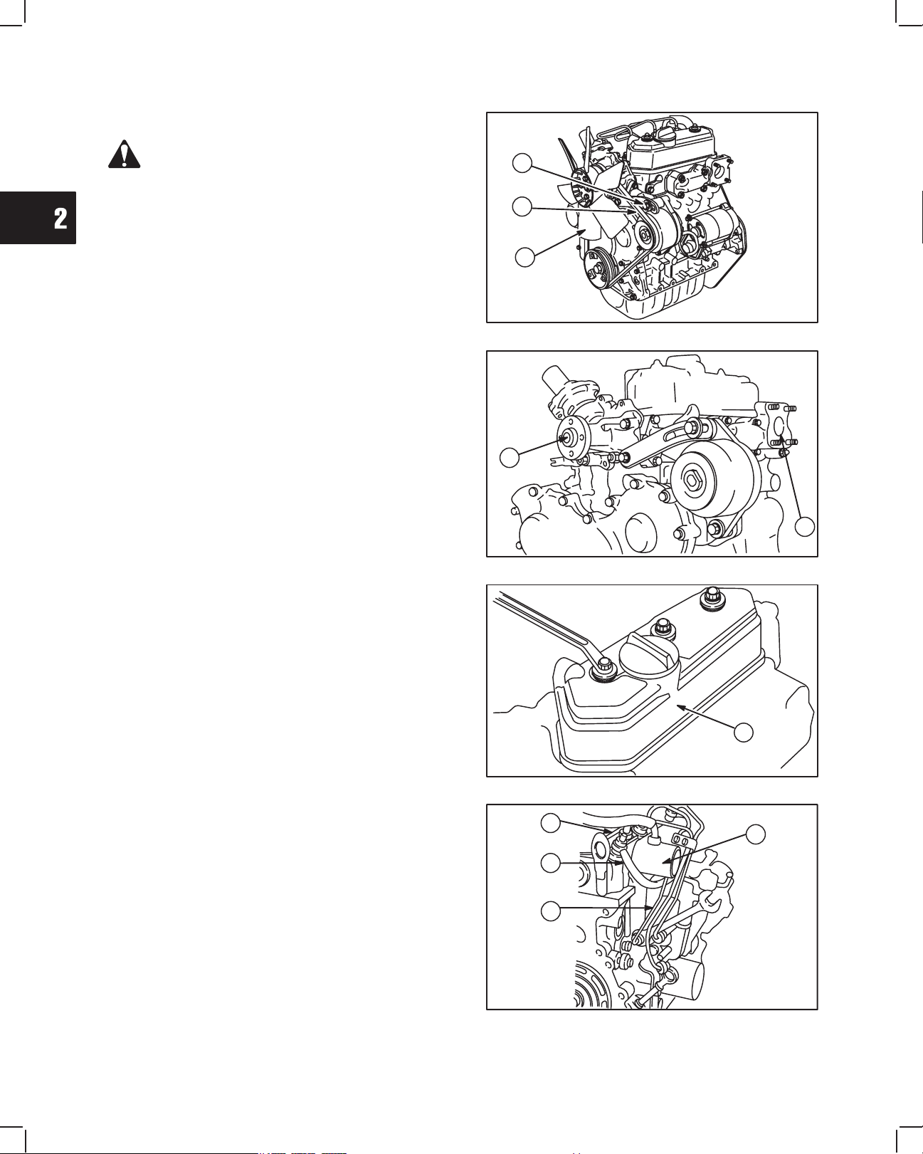
1. Remove the following parts from engine,
Fig. 1-Fig. 5:
a. Alternator adjusting bracket screw
b. V-belt
c. Fan (if equipped)
Fig. 1 – Remove V-belt And Fan
C
B
A
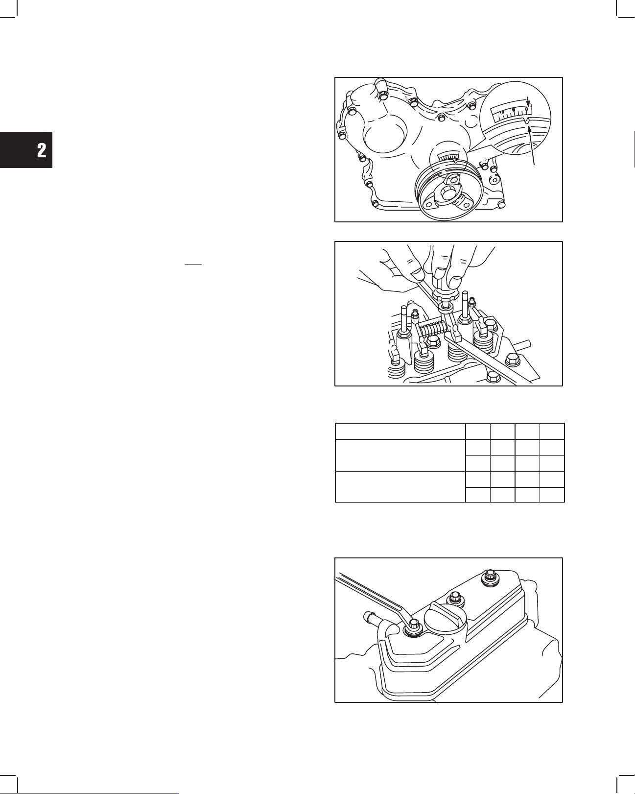
Fig. 2:
d. Water pump
e. Exhaust manifold
NOTE: Remove exhaust system before removing
exhaust manifold.
Fig. 2 – Remove Water Pump And Exhaust Manifold
D
E
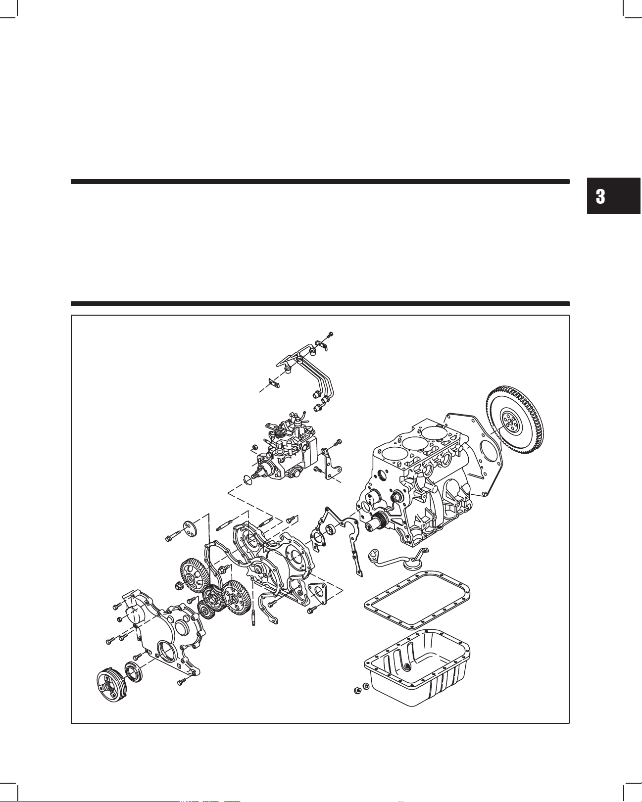
Fig. 3:
f. Valve cover
Discard rubber seal.
Fig. 3 – Remove Valve Cover
F
NOTE: Clean areas around fuel lines and injec-
tors to prevent dirt entry.
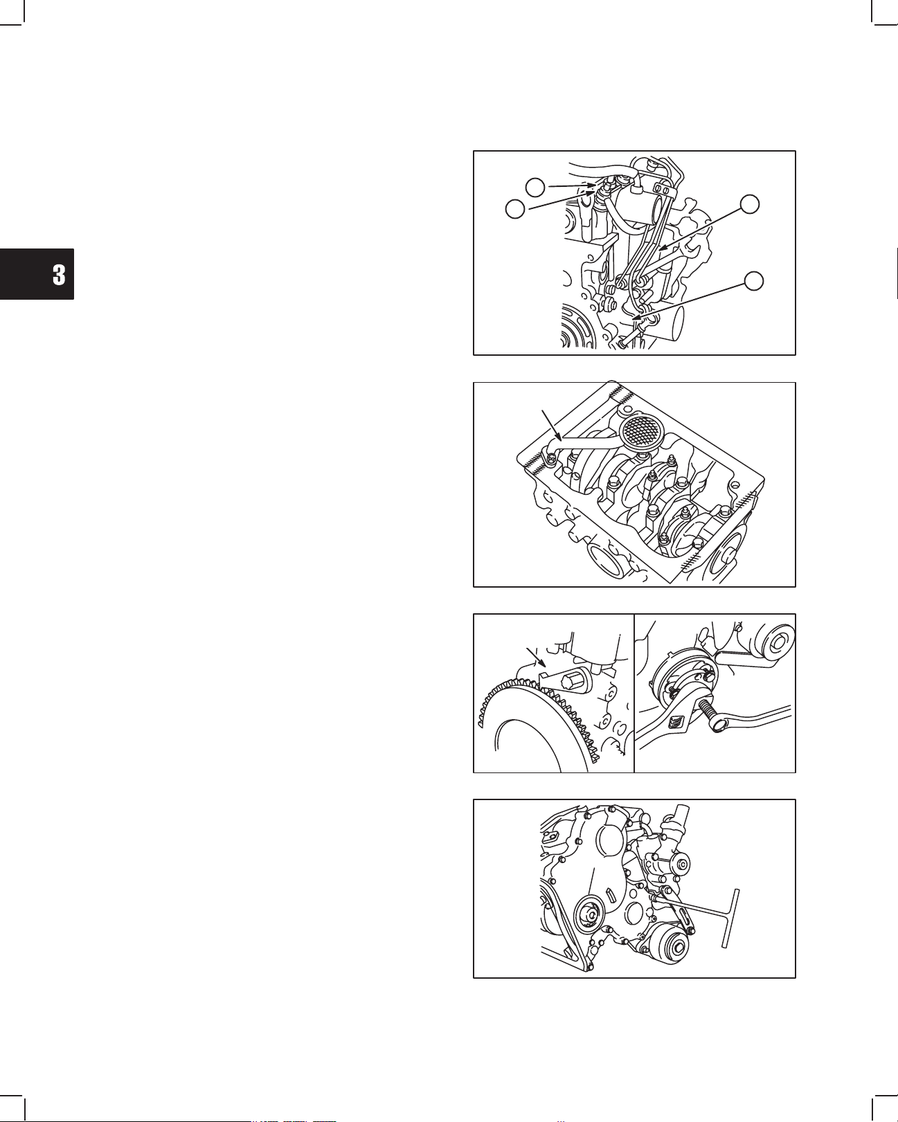
Fig. 4:
g. Fuel delivery lines
h. Fuel return line
i. Glow plug wiring
j. Breather tube and intake manifold
Fig. 4 – Remove Fuel Lines
G
H
I
J
2
3
CYLINDER HEAD AND VALVES
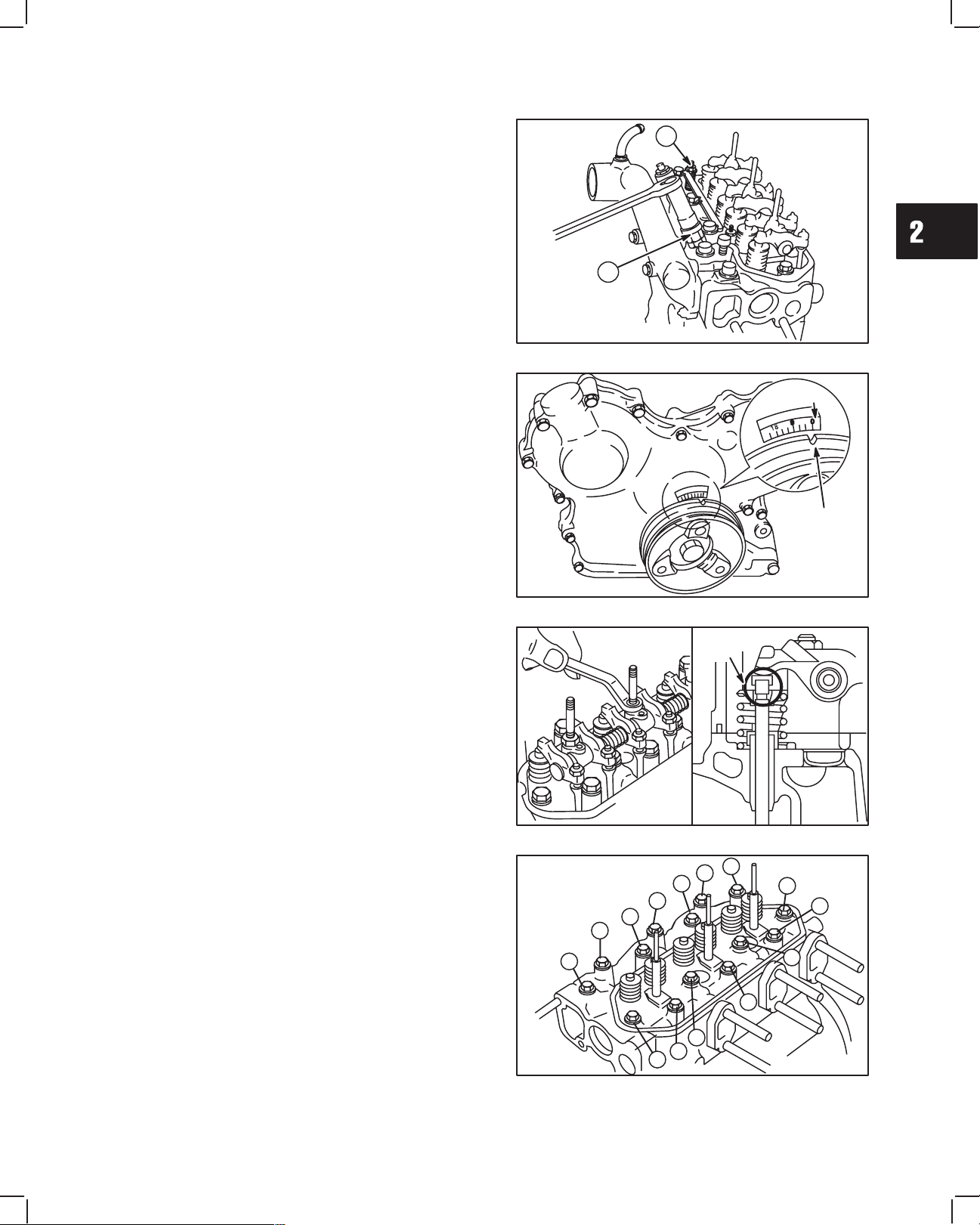
Fig. 5:
k. Fuel injector nozzles
l. Glow plugs
Fig. 5 – Remove Glow Plugs And Injectors
K
L
2. Set No. 1 piston at TDC, Fig. 6:
a. Rotate crankshaft pulley until timing mark on
pulley is aligned with reference point on timing
cover.
b. If intake and exhaust valves have clearance,
No. 1 piston is at TDC – compression stroke.
c. If intake and exhaust valves do not have
clearance, turn crankshaft pulley one
complete revolution. Valves will then have
clearance.
Fig. 6 – Set Cylinder No. 1 At TDC
REFERENCE
POINT
TIMING
MARK
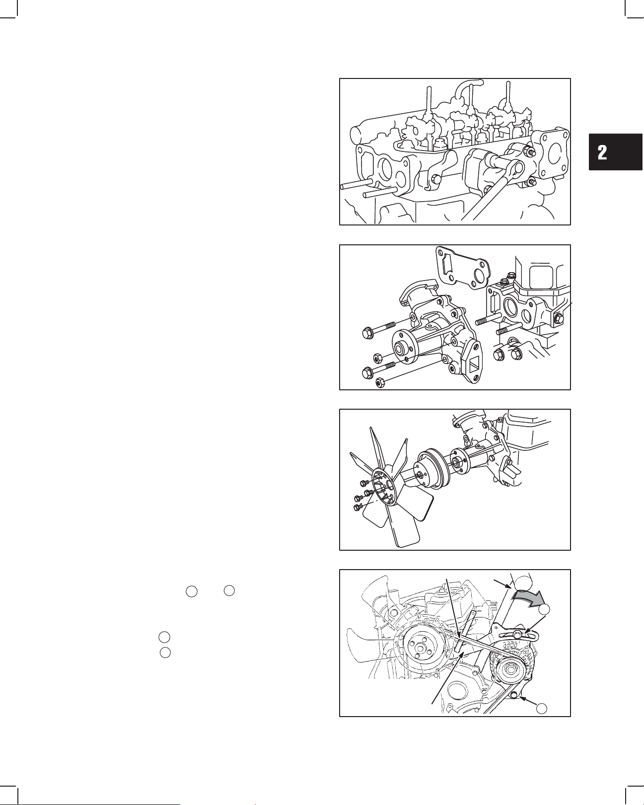
3. Remove rocker arm assembly and push rods,
Fig. 7.
a. Remove valve stem caps.
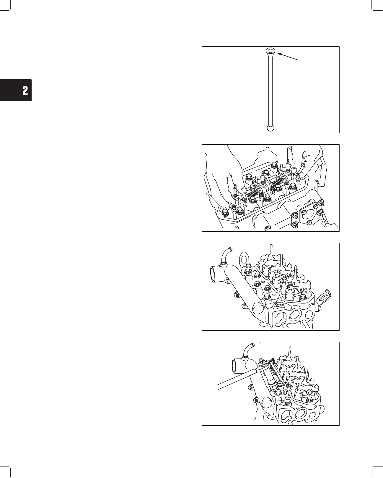
NOTE: Mark push rods so that they may be
reassembled in their original position.
VALV E
STEM
CAP
Fig. 7 – Remove Rocker Arm Assembly And Push Rods
4. Remove cylinder head assembly, Fig. 8.
a. Loosen cylinder head bolts in the order shown.
NOTE: Current style head bolts are 9 mm diame-
ter. Early style head bolts are 8 mm
diameter. Torque specifications are differ-
ent.
Fig. 8 – Loosen Cylinder Head Bolts
3
4
5
6
7
1
2
8
12
11
10
9
14
13
2
4
CYLINDER HEAD AND VALVES
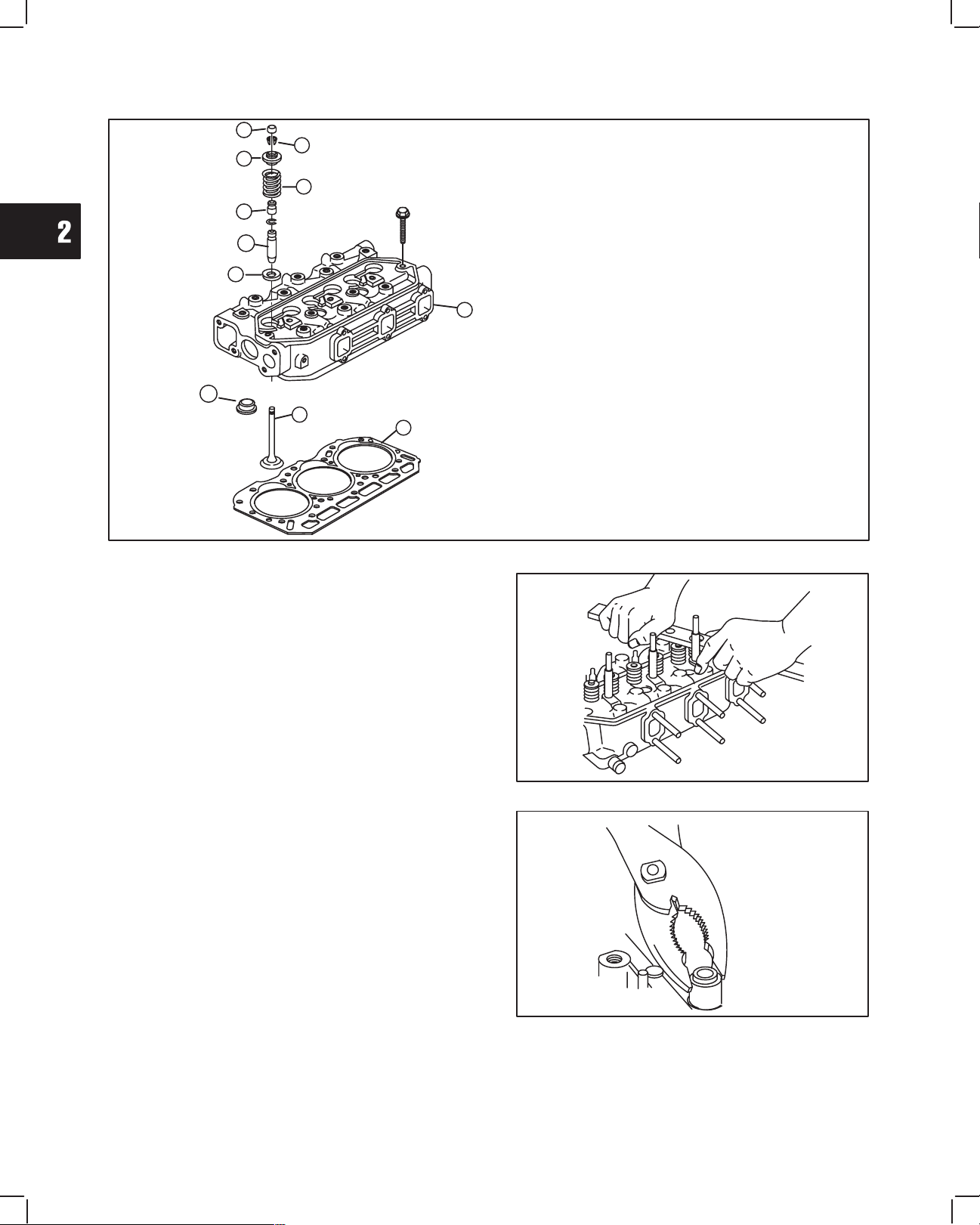
Fig. 9 – Cylinder Head Components
DISASSEMBLE CYLINDER HEAD
1. Cylinder Head Assembly
2. Cylinder Head Gasket
3. Valve Stem Cap
4. Valve Spring Retainer Locks
5. Valve Spring Retainer
6. Valve Spring
7. Valve
8. Valve Spring Seat
9. Valve Stem Seal
10. Valve Guide
11. Combustion Chamber
3
4
5
6
7
1
2
8
9
10
11
Remove valves, Fig. 10.
1. Use valve spring compressor, Tool #19417, to
compress valve springs. Remove the following
parts, Fig. 9:
a. Valve spring retainer locks – 4
b. Valve spring retainer – 5
c. Valve spring – 6
d. IN and EX valve – 7
e. Valve spring seats – 8
Fig. 10 – Remove Valves
2. Remove and discard valve stem seals, Fig. 11.
Fig. 11 – Remove Valve Stem Seal
2
5
CYLINDER HEAD AND VALVES
INSPECT AND REPAIR
1. Check cylinder head mounting surfaces, Fig. 12
and Fig. 13.
Be sure all gasket material is removed from surfaces
before checking. Use a gasket scraper if necessary.
a. Inspect cylinder head for cracks or damage.
b. Use a straight edge and check cylinder head
lower surface for distortion.
Fig. 12 – Check Cylinder Head For Distortion
STRAIGHT
EDGE
Fig. 13:
c. Check intake and exhaust manifold mounting
surfaces.
If mounting surfaces are distorted more than 0.1 mm
(0.004 in.), the cylinder head must be replaced.
It is not recommended that cylinder head
mounting surfaces be resurfaced.
NOTE: Intake manifold and exhaust manifold
may be checked in the same manner. Use
same specifications as cylinder head.
Fig. 13 – Check Cylinder Head For Distortion
CHECK COMBUSTION CHAMBER
Engine Model 522000: combustion chambers are
not replaceable.
Engine Models 432000 and 582000 with date code
after 990111007: combustion chambers are not
replaceable.
NOTE: Only Engine Models 432000 and 582000
with date code before 981225006 have
replaceable combustion chambers.
1. Check combustion chamber, Fig. 14.
a. Use a straight edge and feeler gauge.
If combustion chamber protrudes more than 0.05 mm
(.002 in.) above surface of cylinder head, it must be
replaced.
Fig. 14 – Check Combustion Chamber
COMBUSTION
CHAMBER
COMBUSTION
CHAMBER
2. Remove combustion chamber, Fig. 15.
Insert a 10 mm brass rod through injector nozzle hole
and drive out combustion chamber.
NOTE: Do not damage threads in injector hole.
Fig. 15 – Remove Combustion Chamber
BRASS ROD
COMBUSTION
CHAMBER
2
6
CYLINDER HEAD AND VALVES
3. Install combustion chamber, Fig. 16.
Align locating projection on combustion chamber with
groove in cylinder head. Use a soft hammer and drive
in new combustion chamber until it bottoms.
Fig. 16 – Install Combustion Chamber
COMBUSTION
CHAMBER
CHECK AND REPAIR VALVE GUIDES
1. Check valve guide bushings for wear using reject
gauge, Tool #19382, Fig. 17.
Remove if damaged or if reject gauge enters valve
guide.
Fig. 17 – Check Valve Guide Bushing
REJECT
GAGE
2. Remove valve guide bushing if required, Fig. 18.
a. Use bushing driver, Tool #19367, and press
out valve guide bushing from combustion
chamber side.
b. Check valve guide bushing OD. Then see
specifications below.
Std. Bushing OD: – 11.05 mm (.435 in.)
Replacement Bushing OD: – 11.08 mm (.4362 in.)
c. If bushing OD measurement indicates that a
replacement bushing has already been
installed, the cylinder head must be replaced.
Fig. 18 – Remove Valve Guide Bushing
PRESSING OUT
GUIDE
2
7
CYLINDER HEAD AND VALVES
3. Using bushing driver, Tool #19416, press in new
valve guide bushing until tool bottoms on cylinder
head, Fig. 19.
Fig. 19 – Installing Valve Guide Bushing
VALVES AND SEATS
1. Valve faces may be resurfaced to 45°. See Fig. 20
for dimensions for valves. Lap valves and seats
with valve lapping Tool, #19258 and valve lapping
compound, Tool #94150.
Fig. 20 – Valve Dimensions
SEATING AREA CENTERED
ON VALVE FACE
(1/16” TO 3/64”)
(.040”)
MINIMUM
0.8 mm TO 1.2 mm
1.0 mm
2. Valve seats may be reconditioned using valve seat
cutter, Tool #19446.
NOTE: Check valve guide bushings first. If valve
guides are worn, they must be replaced
before refacing valve seats
If valve seat is wider than dimension shown in Fig. 21,
a narrowing cutter should be used to ensure that
contact area of valve seat is centered on face of valve,
Fig. 20.
a. Use a 60° cutter to narrow seat from bottom
and a 30° cutter to narrow seat from top,
Fig. 21.
NOTE: If valve seat is loose or cracked, replace
cylinder head.
Fig. 21 – Valve Seat Dimensions
45°
VALVE SEAT DIMENSIONS
60° CUTTER
30° CUTTER
(1/16” TO 3/64”)
0.8 mm TO 1.2 mm
3. Measure valve stem diameter at specified
distance from end of valve, as shown in Fig. 22.
Replace IN if less than 5.927 mm (0.2333 in.).
Replace EX if less than 5.923 mm (0.2332 in.).
Fig. 22 – Measure Valve Stem Diameter
35 mm
(1.38”)
2
8
CYLINDER HEAD AND VALVES
4. Inspect valve stem cap for wear, Fig. 23.
Replace if cap is worn recessed.
Fig. 23 – Check Valve Stem Cap
5. Check valve springs for squareness and free
length, Fig. 24.
Replace if out of square more than 1.0 mm
(.040 in.).
Replace if free length is less than 30.7 mm
(1.209 in.).
Fig. 24 – Check Valve Springs
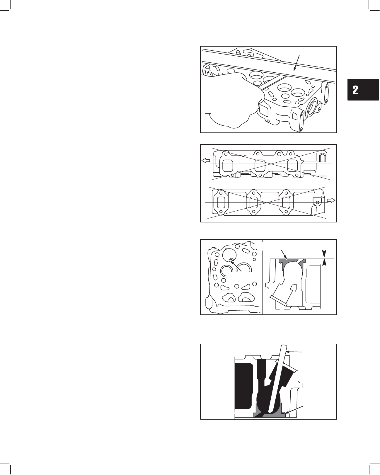
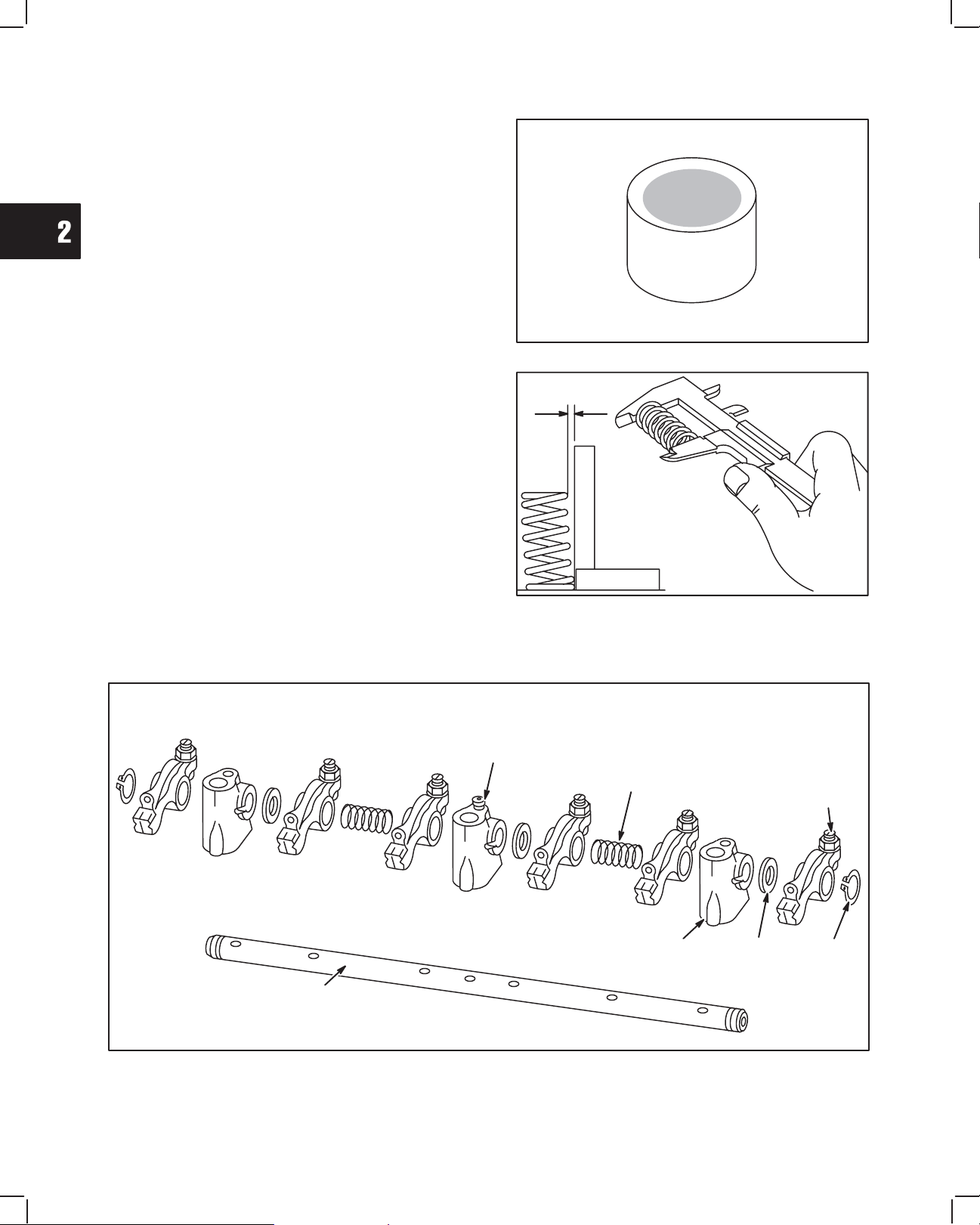
DISASSEMBLE ROCKER ARM SHAFT
1. Remove snap rings from ends of rocker arm shaft. Remove set screw from center rocker arm support. Disassemble
rocker arm assembly. Note position of all components, Fig. 25.
Fig. 25 – Rocker Arm Components
SET
SCREW
(1)
SPRING
(2)
ROCKER
ARM
(6)
SNAP
RING
(2)
SPACER
(3)
ROCKER
ARM SUPPORT
(3)
ROCKER
ARM
SHAFT
2
9
CYLINDER HEAD AND VALVES
2. Check rocker arms and shaft, Fig. 26.
a. Check rocker arm-bearing surface.
Replace if greater than 10.03 mm (0.395 in.).
b. Check rocker arm shaft
Replace if less than 9.96 mm (0.392 in.).
c. Check rocker arm studs for stripped threads
and replace if required.
Fig. 26 – Checking Rocker Arm And Shaft
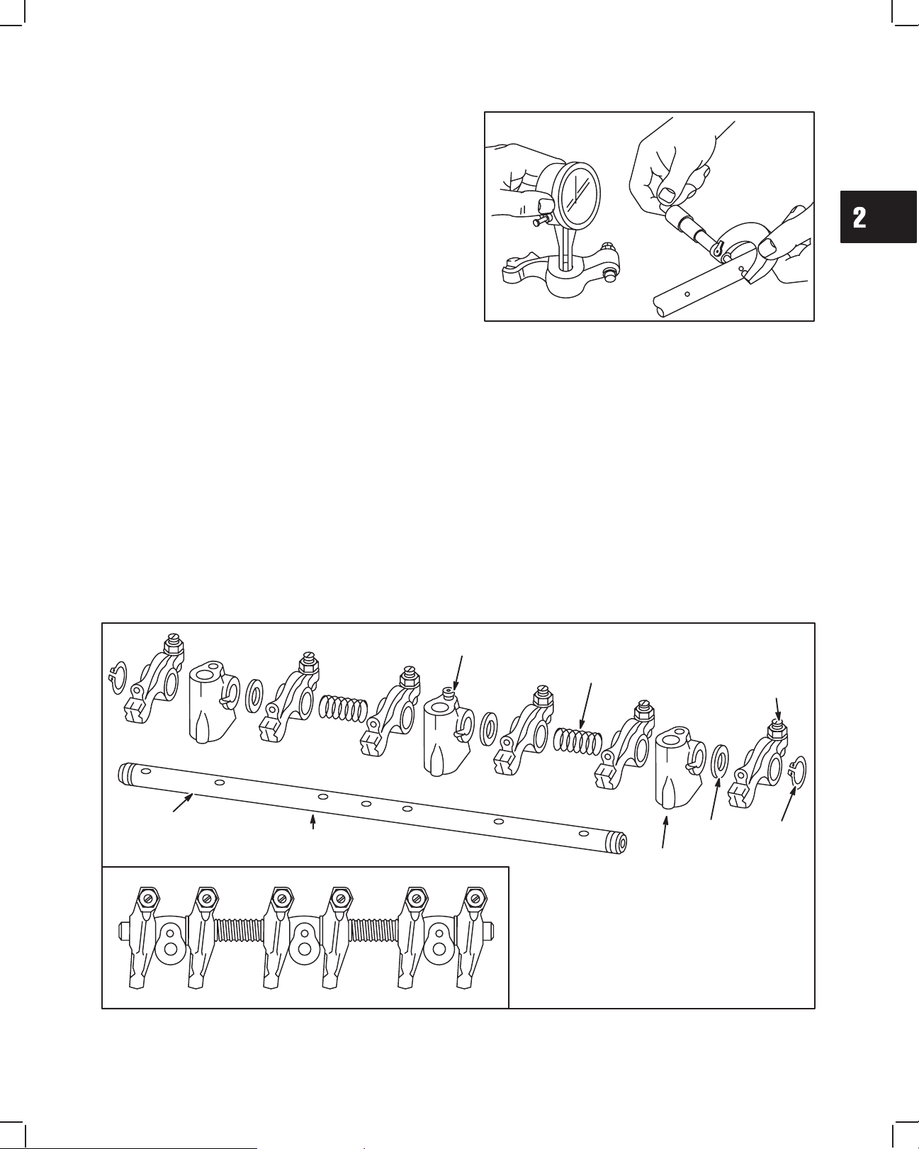
ASSEMBLE ROCKER ARM SHAFT
1. Oil all components before assembling. Small grooves in rocker shaft next to oil holes must face down. Assemble
rocker arm components, noting order of assembly as shown in Fig. 27. Note position of three thrust washers.
Install set screw in center rocker arm shaft support.
Fig. 27 – Rocker Arm Components
SET
SCREW
(1)
SPRING
(2)
ROCKER
ARM
(6)
SNAP
RING
(2)
THRUST
WASHER
(3)
ROCKER
ARM SUPPORT
(3)
ROCKER
ARM
SHAFT
OIL
GROOVES
DOWN
2
10
CYLINDER HEAD AND VALVES
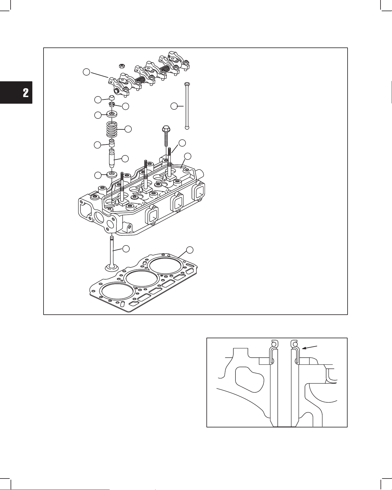
Fig. 28 – Cylinder Head Components
ASSEMBLE CYLINDER HEAD
1. Cylinder Head
2. Cylinder Head Gasket
3. Valve Stem Cap
4. Valve Spring Retainer Locks
5. Valve Spring Retainer
6. Valve Spring
7. Valve
8. Valve Spring Seat
9. Valve Stem Seal
10. Valve Guide
11. Push Rod
12. Rocker Arm Assembly
13. Rocker Arm Stud
3
4
5
6
7
1
2
8
10
9
NOTE: When replacing rocker arm studs,
torque to 20.0 Nm (180 in. lbs.).
13
11
12
1. Install new valve stem seals, Fig. 29. Oil inner
surface and lip of seal before installing. Press seal
on to valve guide bushing until it bottoms.
Fig. 29 – Install Valve Stem Seals
VALVE STEM
SEAL
(CUTAWAY VIEW)
2
11
CYLINDER HEAD AND VALVES
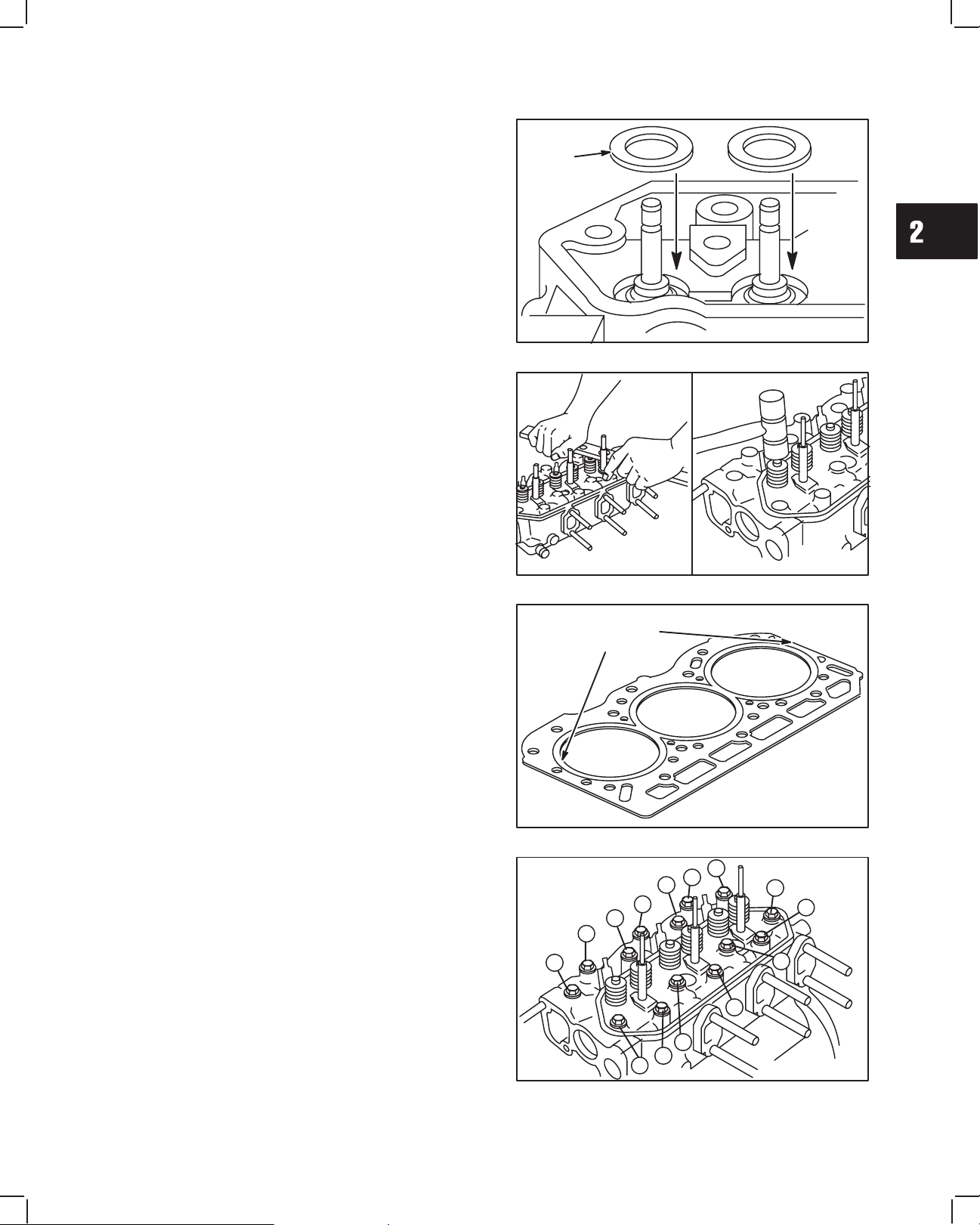
2. Install valve spring seats, Fig. 30.
NOTE: Lightly coat valve stems with Valve Guide
Lubricant #93963 before installing valves.
3. Install valves.
Fig. 30 – Install Valve Spring Seats And Valves
VALV E
SPRING
SEATS
4. Install valve springs with valve spring compressor,
Tool #19417, Fig. 31.
NOTE: After installing valve spring retainer locks,
tap valve spring retainer lightly with a soft
hammer to ensure locks are seated.
Fig. 31 – Install Valve Springs
INSTALL CYLINDER HEAD
1. Place cylinder head gasket over alignment dowels
on cylinder block, Fig. 32.
NOTE: Make sure coolant, oil passages and head
bolt holes are aligned.
Fig. 32 – Install Cylinder Head Gasket
ALIGNMENT
DOWEL
LOCATIONS
2. Install cylinder head assembly, Fig. 33. Lubricate
threads of cylinder head bolts with engine oil.
Torque head bolts in 14.0 Nm (10 ft. lbs.) incre-
ments in sequence shown.
NOTE: Current style head bolts are 9 mm
diameter. Early style head bolts are 8 mm
diameter.
a. Torque 9 mm head bolts to 43.0 Nm (32 ft. lbs.).
b. Torque 8 mm head bolts to 34.0 Nm (25 ft. lbs.).
NOTE: Engine Models 58A447 588447 have 10
mm diameter head bolts. Torque head
bolts to 68 Nm (60 ft. lbs.).
Fig. 33 – Install Cylinder Head Assembly
3
4
5
6
7
1
2
8
12
11
10
9
14
13
2
12
CYLINDER HEAD AND VALVES
3. Lubricate push rods with engine oil then install with
recessed end up, Fig. 34.
Fig. 34 – Install Push Rods
RECESSED
END UP
4. Install valve stem caps on valve stems. Install
rocker arm assembly, Fig. 35. Install washers and
torque nuts to 19.0 Nm (170 in. lbs.).
NOTE: Make sure rocker adjustment studs are
seated in recessed end of push rods.
Fig. 35 – Install Rocker Arm Assembly
5. Install intake manifold with new gasket, Fig. 36.
a. Torque screws to 8.0 Nm (70 in. lbs.).
Fig. 36 – Install Intake Manifold
6. Install Injectors, fuel lines and glow plugs, Fig. 37.
a. Torque injectors to 61.0 Nm (45 ft. lbs.).
b. Torque fuel return line to 27.0 Nm (20 ft. lbs.).
c. Torque fuel delivery lines to 25.0 Nm (220 in.
lbs.).
d. Torque glow plugs to 17.0 Nm (150 in. lbs.).
Fig. 37 – Install Glow Plugs And Injectors
2
13
CYLINDER HEAD AND VALVES
7. Install exhaust manifold with new gasket, Fig. 38.
a. Torque screws to 19.0 Nm (170 in. lbs.).
Fig. 38 – Install Exhaust Manifold
GENERAL ASSEMBLY
1. Install water pump with new gasket, Fig. 39.
a. Torque screws and nuts to 19.0 Nm (170 in.
lbs.).
Fig. 39 – Install Water Pump
2. Install water pump pulley, Fig. 40.
3. Install fan (if equipped).
a. Torque screws to 7.0 Nm (60 in. lbs.).
Fig. 40 – Install Water Pump Pulley And Fan
4. Install V-belt, Fig. 41.
5. Install alternator bolts A and B .
Belt deflection limit is 10–12 mm/10 kg
(3/8–1/2 in/22 lbs.).
a. Torque bolt A to 19.0 Nm (170 in. lbs.).
b. Torque bolt B to 61.0 Nm (45 ft. lbs.).
Fig. 41 – Adjusting V-belt
3/8 – 1/2 Inch
(10 – 12 mm)
BELT MOVEMENT
BELT
A
B
HANDLE
2
14
CYLINDER HEAD AND VALVES
ADJUST VALVES
1. Before adjusting valves, make sure that No. 1
cylinder is at TDC – compression stroke, Fig. 42.
Fig. 42 – Set Cylinder No. 1 at TDC
REFERENCE
POINT
TIMING
MARK
a. Adjust valves and check, Fig. 43.
Valve Clearance (cold) IN and EX 0.20 mm (0.008 in.)
b. Torque adjusting screws and jam nuts to 11.0
Nm (95 in. lbs.).
Fig. 43 – Adjust Valve Clearances
With No. 1 piston at TDC of compression stroke, check
and adjust valve clearances for cylinders shown in
chart at right.
Rotate crankshaft one complete turn (360°)"clockwise
to check and adjust remaining valves.
Piston Position Cylinder 1 2 3
No. 1 piston at TDC, of
IN
l l
No
.
1 piston at TDC
,
of
compression stroke
EX
l l
Rotate Crankshaft 360°
IN
l
Rotate Crankshaft 360
clockwise
EX
l
2. Install valve cover with new rubber seal, Fig. 44.
a. Torque cover nuts to 7.0 Nm (50 in. lbs.).
NOTE: Make sure rubber seal is in groove in
valve cover.
Fig. 44 – Install Valve Cover
3
1MAY 2002
BRIGGS & STRATTON DAIHATSU 3 CYLINDER
LIQUID-COOLED DIESEL ENGINE REPAIR MANUAL (MS-1055)
Section 3
Timing Gears and Gear Case
Section Contents
Page
REMOVE TIMING GEAR COVER AND GEARS 2. . . . . . . . . . . . . . . . . . . . . . . . . . . . . . . . . . . . . . . . . . . . . . . . . . . . . .
CHECKING GEARS 3. . . . . . . . . . . . . . . . . . . . . . . . . . . . . . . . . . . . . . . . . . . . . . . . . . . . . . . . . . . . . . . . . . . . . . . . . . . . . .
REMOVE GEAR CASE 4. . . . . . . . . . . . . . . . . . . . . . . . . . . . . . . . . . . . . . . . . . . . . . . . . . . . . . . . . . . . . . . . . . . . . . . . . . .
REPLACE TIMING GEAR COVER OIL SEAL 5. . . . . . . . . . . . . . . . . . . . . . . . . . . . . . . . . . . . . . . . . . . . . . . . . . . . . . . .
ASSEMBLE TIMING GEAR CASE AND GEARS 5. . . . . . . . . . . . . . . . . . . . . . . . . . . . . . . . . . . . . . . . . . . . . . . . . . . . . .
3
2
TIMING GEARS AND GEAR CASE
REMOVING TIMING GEAR COVER
AND GEARS
Make sure that #1 cylinder is at TDC, compression
stroke. See Section 2, Fig. 6.
Remove V-belt and fan (if equipped). Drain oil from
engine.
NOTE: Clean areas around fuel lines and injec-
tors to prevent dirt entry.
1. Remove the following parts, Fig. 1.
a. Glow plug wiring.
b. Glow plugs.
c. Injector pump bracket.
d. Remove fuel delivery lines.
Fig. 1 – Remove Fuel Delivery Lines
B
A
C
D
2. Remove the following parts, Fig. 2.
a. Remove oil pan and discard gasket.
b. Remove oil pick-up tube and strainer. Discard
gasket.
Fig. 2 – Removing Oil Pan
OIL PICK-UP
TUBE
3. Remove bell housing adapter screw if equipped.
and install flywheel holder, Tool #19418.
4. LEAVE TOOL INSTALLED.
a. Remove crankshaft pulley using Tool
# 19420, Fig. 3.
Fig. 3 – Removing Crankshaft Pulley
FLYWHEEL
HOLDER
5. Remove timing gear cover, Fig. 4.
a. Discard timing gear cover gasket.
Fig. 4 – Removing Timing Gear Cover
3
3
TIMING GEARS AND GEAR CASE
6. Remove oil pump drive gear, Fig. 5.
a. Check oil pump drive gear for damaged teeth.
Fig. 5 – Removing Oil Pump Gear
OIL
PUMP
GEAR
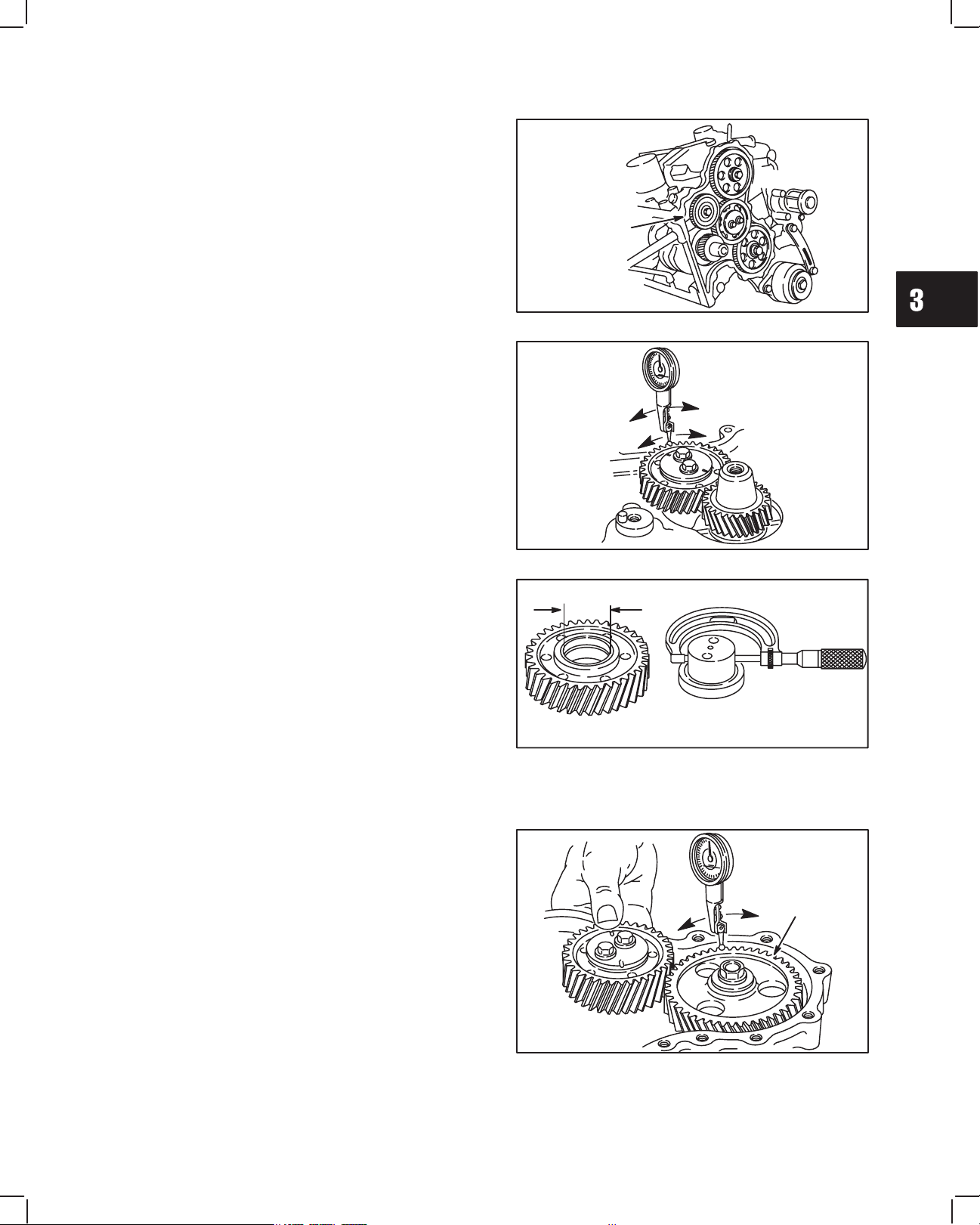
CHECKING GEARS
Inspect gear teeth for wear or damage.
CHECK GEARS IN SEQUENCE SHOWN.
1. Check gear backlash between idler gear and
crankshaft gear using dial indicator as shown in
Fig. 6.
a. Set tip of indicator on gear tooth, then rock
idler gear back and forth noting indicator
reading.
NOTE: Crankshaft must not turn while checking.
Fig. 6 – Checking Idler Gear Backlash
IDLER
GEAR
CRANKSHAFT
GEAR
2. If backlash exceeds 0.2 mm (.008”) check idler
gear bearing and shaft for wear, Fig. 7.
Reject Dimension: Idler Gear ID –
34.17 mm (1.345”)
Idler Gear Shaft OD –
33.91 mm (1.335”)
a. If idler gear bearing and shaft are within
specification, replace with new idler gear and
recheck.
b. If backlash exceeds 0.2 mm (.008”) with NEW
idler gear, crankshaft gear is worn.
NOTE: If crankshaft gear is worn the crankshaft
must be replaced.
Fig. 7 – Checking Idler Gear And Shaft
IDLER
GEAR
IDLER
GEAR
SHAFT
3. Hold idler gear as shown and check gear backlash
between camshaft timing gear and idler gear using
dial indicator, Fig. 8.
Camshaft timing gear backlash must not exceed
0.2 mm (.008”).
NOTE: Idler gear must not turn while checking.
Fig. 8 – Checking Camshaft Timing Gear Backlash
CAMSHAFT
TIMING
GEAR
IDLER
GEAR
3
4
TIMING GEARS AND GEAR CASE
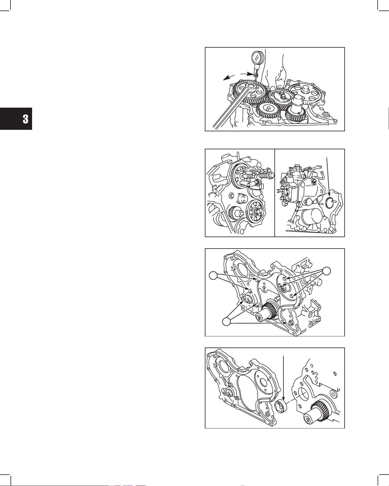
4. Hold idler gear as shown and check gear backlash
between injector pump timing gear and idler gear
using dial indicator, Fig. 9.
Injector pump timing gear backlash must not exceed
0.2 mm (.008”).
NOTE: Idler gear must not turn while checking.
If gears are worn it is recommended that they be
replaced as a set.
Fig. 9 – Checking Injector Pump
Timing Gear Backlash
REMOVE GEAR CASE
1. Remove injector pump timing gear with a three jaw
puller, Fig. 10.
a. Remove 2 nuts and injector pump. Discard
O-ring.
Fig. 10 – Removing Injector Pump
O-RING
2. Remove parts in sequence shown, Fig. 11.
a. Remove 3 screws and camshaft retainer.
b. Remove remaining 5 screws.
Fig. 11 – Removing Timing Gear Case
A
B
B
3. Remove timing gear case and discard gasket,
Fig. 12.
a. Remove oil pump rotor from cylinder block.
Fig. 12 – Remove Timing Gear Case
ROTOR
 Loading...