


Toro 74237, 74237CP, 74238, 74238CP, 74239 Service Manual
...LCE Products
Z Master 500 Series
Gasoline Engine Models
Service Manual

ABOUT THIS MANUAL
This service manual was written expressly for Toro service technicians. The Toro Company has made every effort to make the information in this manual complete and correct.
Basic shop knowledge and mechanical/electrical skills are assumed. The Table of Contents lists the systems and the related topics covered in this manual.
The following service materials are available in addition to this service manual:
Hydrostatic Pumps: |
Hydro-Gear BDP-10A/16A/21L - Service and Repair Manual |
|
Form #492-4789 |
Wheel Motors: |
Parker/Ross Wheel Motor Service Manual |
|
Form #492-4753 |
|
|
Gas Engine: |
Through engine manufacturer |
|
|
Hydraulic Troubleshooting: |
Interactive hydraulic troubleshooting and failure analysis on compact disk |
|
Form #492-4777 |
|
|
Electrical Troubleshooting: |
Interactive electrical troubleshooting and wiring diagrams on compact disk |
|
Form #492-9143 |
|
|
Z Master 500 Series gasoline engine machines, model years 2004 and 2005 are covered in this manual. This manual may also be specified for use on later model products.
The hydrostatic drive system is precision machinery. Maintain strict cleanliness control during all stages of service and repair. Cover or cap all hose ends and fittings whenever they are exposed.
Even a small amount of dirt or other contamination can severely damage the system.
We are hopeful that you will find this manual a valuable addition to your service shop. If you have any questions or comments regarding this manual, please contact us at the following address:
The Toro Company
LCE Service Training Department
8111 Lyndale Avenue South
Bloomington, MN 55420
The Toro Company reserves the right to change product specifications or this manual without notice.
Copyright© All Rights Reserved
©2005 The Toro Company
THIS PAGE INTENTIONALLY LEFT BLANK.

TABLE OF CONTENTS
SAFETY INFORMATION |
|
|
General Information . . . . . . . . . . . . . . . . . . . . . . . . . . . . . . . . . |
1-2 |
|
Think Safety First . . . . . . . . . . . . . . . . . . . . . . . . . . . . . . . . . . |
|
1-2 |
SPECIFICATIONS |
|
|
Kawasaki Liquid Cooled Product Shots . . . . . . . . . . . . . . . . . . . . . . . . . |
|
2-2 |
Kohler EFI Product Shots . . . . . . . . . . . . . . . . . . . . . . . . . . . . . . |
|
2-3 |
Kohler Gas Product Shots . . . . . . . . . . . . . . . . . . . . . . . . . . . . . . |
|
2-4 |
Kawasaki Gas Product Shots . . . . . . . . . . . . . . . . . . . . . . . . . . . . . |
|
2-5 |
Engines . . . . . . . . . . . . . . . . . . . . . . . . . . . . . . . . . . . . . |
|
2-6 |
Dimensions and Weight . . . . . . . . . . . . . . . . . . . . . . . . . . . . . . . |
|
2-7 |
Construction . . . . . . . . . . . . . . . . . . . . . . . . . . . . . . . . . . . . |
|
2-7 |
Fuel System . . . . . . . . . . . . . . . . . . . . . . . . . . . . . . . . . . . . |
|
2-7 |
Traction System . . . . . . . . . . . . . . . . . . . . . . . . . . . . . . . . . . |
2-8 |
|
Deck Drive . . . . . . . . . . . . . . . . . . . . . . . . . . . . . . . . . . . . |
|
2-8 |
Tires . . . . . . . . . . . . . . . . . . . . . . . . . . . . . . . . . . . . . . . |
2-8 |
|
Electrical System . . . . . . . . . . . . . . . . . . . . . . . . . . . . . . . . . . |
|
2-8 |
Cutting Decks . . . . . . . . . . . . . . . . . . . . . . . . . . . . . . . . . . . |
|
2-9 |
General Specifications |
|
|
Greasing and Lubrication . . . . . . . . . . . . . . . . . . . . . . . . . . . . . |
2-10 |
|
Model and Serial Number Locations . . . . . . . . . . . . . . . . . . . . . . . . . |
2-11 |
|
Available Service Manuals . . . . . . . . . . . . . . . . . . . . . . . . . . . . . . |
2-11 |
|
Torque Specifications . . . . . . . . . . . . . . . . . . . . . . . . . . . . . . . . |
|
2-12 |
Standard Torque for Dry, Zinc Plated, and Steel Fasteners (Inch Series) . . . . . . . . . . . . |
2-13 |
|
Standard Torque for Dry, Zinc Plated, and Steel Fasteners (Metric Fasteners) . . . . . . . . . . |
|
2-14 |
Other Torque Specifications |
|
|
SAE Grade 8 Steel Set Screws . . . . . . . . . . . . . . . . . . . . . . . . . . . |
2-15 |
|
Thread Cutting Screws (Zinc Plated Steel) . . . . . . . . . . . . . . . . . . . . . . |
2-15 |
|
Wheel Bolts and Lug Nuts . . . . . . . . . . . . . . . . . . . . . . . . . . . . . |
|
2-15 |
Thread Cutting Screws (Zinc Plated Steel) . . . . . . . . . . . . . . . . . . . . . . |
2-15 |
|
Equivalents and Conversions . . . . . . . . . . . . . . . . . . . . . . . . . . . . . |
|
2-16 |
US to Metric Conversions . . . . . . . . . . . . . . . . . . . . . . . . . . . . . . . |
2-17 |
|
CHASSIS |
|
|
Caster Fork Assembly Removal . . . . . . . . . . . . . . . . . . . . . . . . . . . . |
3-2 |
|
Replacing the Caster Bearings . . . . . . . . . . . . . . . . . . . . . . . . . . . . . |
3-2 |
|
Caster Fork Assembly . . . . . . . . . . . . . . . . . . . . . . . . . . . . . . . . |
3-4 |
|
Front Wheel Removal and Bearing Replacement . . . . . . . . . . . . . . . . . . . . . |
3-5 |
|
Fuel Tank Removal |
|
|
Left Side Fuel Tank Removal . . . . . . . . . . . . . . . . . . . . . . . . . . . . |
3-6 |
|
Left Side Fuel Tank Installation . . . . . . . . . . . . . . . . . . . . . . . . . . . |
3-7 |
|
Right Side Fuel Tank Removal and Installation . . . . . . . . . . . . . . . . . . . . . |
3-7 |
|
Hood Assembly Removal . . . . . . . . . . . . . . . . . . . . . . . . . . . . . . . |
3-8 |
|
Hood Assembly Installation . . . . . . . . . . . . . . . . . . . . . . . . . . . . . . |
3-8 |
|
Brake Lever Removal . . . . . . . . . . . . . . . . . . . . . . . . . . . . . . . |
. 3-8 |
|
Brake Lever Installation . . . . . . . . . . . . . . . . . . . . . . . . . . . . . . . |
. 3-10 |
|
Brake Band Removal . . . . . . . . . . . . . . . . . . . . . . . . . . . . . . . . |
3-10 |
|
Brake Band Installation . . . . . . . . . . . . . . . . . . . . . . . . . . . . . . . . |
3-10 |
|
Brake Shaft Removal . . . . . . . . . . . . . . . . . . . . . . . . . . . . . . . . |
3-11 |
|
Brake Shaft Installation . . . . . . . . . . . . . . . . . . . . . . . . . . . . . . . . |
3-13 |
|
Adjusting the Parking Brake . . . . . . . . . . . . . . . . . . . . . . . . . . . . . . |
3-13 |
|
Deck Lift Lever Removal . . . . . . . . . . . . . . . . . . . . . . . . . . . . . . . |
3-13 |
|
Deck Lift Lever Installation . . . . . . . . . . . . . . . . . . . . . . . . . . . . . . |
3-17 |
|
Z Master 500 Gas Series Service Manual |
i |

TABLE OF CONTENTS
CHASSIS cont. |
|
|
|
Motion Control Assembly Removal . |
. . . . . . . . . . . . . . . . . . . . . . . . . |
. |
3-20 |
Motion Control Assembly Installation |
. . . . . . . . . . . . . . . . . . . . . . . . . |
. |
3-22 |
HYDRAULIC SYSTEM
Hydrostatic Pump Removal . . . . . . . . . . . . . . . . . . . . . . . . . . . . . . 4-2
Hydrostatic Pump Installation |
. . . . . . . . . . . . . . . . . . . . . . . . |
. . . . |
. 4-4 |
|||
Wheel Motor Removal . . |
. . . . . . . . . . . . . . . . . . . . . . . . . |
. |
. |
. |
. |
. 4-7 |
Wheel Motor Installation . |
. . . . . . . . . . . . . . . . . . . . . . . . . |
. |
. |
. |
. |
. 4-9 |
Adjusting the Handle Neutral . . . . . . . . . . . . . . . . . . . . . . . . . . . . . |
4-12 |
|
Setting the Hydraulic Pump Neutral . . . . . . . . . . . . . . . . . . . . . . . . . . . |
4-14 |
|
Setting the RH Hydraulic Pump Neutral . . . . . . . . . . . . . . . . . . . . . . . . . |
4-14 |
|
Setting the LH Hydraulic Pump Neutral . . . . . . . . . . . . . . . . . . . . . . . . . |
4-15 |
|
Adjusting the Tracking . . . . . . . . . . . . . . . . . . . . . . . . . . . . . . . . |
4-16 |
|
Replacing the Pump Drive Belt . . . . . . . . . . . . . . . . . . . . . . . . . . . . . |
4-17 |
|
Purging the Hydraulic System . . . . . . . . . . . . . . . . . . . . . . . . . . . . . |
4-18 |
|
Hydraulic Flow Testing Procedure . . . . . . . . . . . . . . . . . . . . . . . . . . . . 4-18 |
||
Pushing the Machine by Hand . . . . . . . . . . . . . . . . . . . . . . . . . . . . . |
4-20 |
|
Changing to Machine Operation . . . . . . . . . . . . . . . . . . . . . . . . . . . . |
4-21 |
|
ENGINE |
|
|
Kohler Air-Cooled Engine Removal . . . . . . . . . . . . . . . . . . |
. . . . . . . . . 5-2 |
|
Kohler Air-Cooled Engine Installation . . . . . . . . . . . . . . . . . . . . . . . . . . |
5-5 |
|
Kawasaki Air-Cooled Engine Removal . . . . . . . . . . . . . . . . . |
. . . . . . . . . 5-8 |
|
Kawasaki Air-Cooled Engine Installation . . . . . . . . . . . . . . . . . . . . . . . . . |
5-10 |
|
28 HP Kohler EFI Air-Cooled Engine Removal . . . . . . . . . . . . . . . . . . . . . . |
5-13 |
|
28 HP Kohler EFI Air-Cooled Engine Installation . . . . . . . . . . . . . . . . . . . . . . |
5-19 |
|
Kohler Electronic Fuel Injection (EFI) Models |
|
|
EFI Fuel System . . . . . . . . . . . . . . . . . . . . . . . . . . . . . . . . . |
5-24 |
|
EFI Electrical System . . . . . . . . . . . . . . . . . . . . . . . . . . . . . . . |
5-25 |
|
27 HP Kawasaki Liquid-Cooled Engine Removal . . . . . . . . . . . . . . . . . . . . . |
5-26 |
|
27 HP Kawasaki Liquid-Cooled Engine Installation . . . . . . . . . . . . . . . . . . . . . |
5-33 |
|
Cooling Fan Assembly Removal - 27 HP Kawasaki Liquid-Cooled Engine . . . . . . . . . . . . |
5-41 |
|
Cooling Fan Assembly Installation . . . . . . . . . . . . . . . . . . . . . . . . . . . |
5-43 |
|
ELECTRICAL |
|
|
General . . . . . . . . . . . . . . . . . . . . . . . . . . . . . . . . . . . . . . |
6-2 |
|
Relays . . . . . . . . . . . . . . . . . . . . . . . . . . . . . . . . . . . . . . |
6-2 |
|
PTO Switch . . . . . . . . . . . . . . . . . . . . . . . . . . . . . . . . . . . . |
6-4 |
|
Ignition Switch . . . . . . . . . . . . . . . . . . . . . . . . . . . . . . . . . . . |
6-6 |
|
Neutral Safety Switch . . . . . . . . . . . . . . . . . . . . . . . . . . . . . . . . |
6-7 |
|
Park Brake Switch . . . . . . . . . . . . . . . . . . . . . . . . . . . . . . . . . . |
6-8 |
|
Seat Switch . . . . . . . . . . . . . . . . . . . . . . . . . . . . . . . . . . . . |
6-9 |
|
Seat Delay Module . . . . . . . . . . . . . . . . . . . . . . . . . . . . . . . . . |
6-11 |
|
Temperature Gauge Liquid-Cooled Engine Only . . . . . . . . . . . . . . . . . . . . . . |
6-12 |
|
Temperature Sender . . . . . . . . . . . . . . . . . . . . . . . . . . . . . . . . . |
6-14 |
|
Hour Meter . . . . . . . . . . . . . . . . . . . . . . . . . . . . . . . . . . . . |
6-14 |
|
Voltmeter Gauge . . . . . . . . . . . . . . . . . . . . . . . . . . . . . . . . . . |
6-15 |
|
Electric PTO Clutch . . . . . . . . . . . . . . . . . . . . . . . . . . . . . . . . . |
6-16 |
|
Coil Resistance Measurement . . . . . . . . . . . . . . . . . . . . . . . . . . . |
6-17 |
|
Measuring Clutch Current Draw . . . . . . . . . . . . . . . . . . . . . . . . . . . |
6-17 |
|
Kohler EFI Wiring Diagram . . . . . . . . . . . . . . . . . . . . . . . . . . . . . . |
6-18 |
|
Kohler A/C (Air Cooled) Wiring Diagram . . . . . . . . . . . . . . . . . . . . . . . . . |
6-19 |
|
ii |
Z Master 500 Gas Series Service Manual |

TABLE OF CONTENTS
ELECTRICAL cont. |
|
|
|
|
|
|
Kawasaki A/C (Air Cooled) Wiring Diagram . . . |
. . . . . . . . . . . . . . . . . . . . . |
6-20 |
||||
Kawasaki L/C (Liquid Cooled) Wiring Diagram . . |
. . . . . . . . . . . . . . . . . . . . . |
6-21 |
||||
MOWER DECKS/PTO |
|
|
|
|
|
|
Electric PTO Clutch Removal . . . . . . . . |
. . |
. . . . . . . . . . . |
. . |
. |
. . . . . 7-2 |
|
Electric PTO Clutch Installation . . . . . . . . |
. . |
. . . . . . . . . . . |
. . |
. |
. . . . . 7-4 |
|
Mower Deck Removal (52, 60, 72”) . . . . . . |
. . . . . . . . . . . . . . . . . . . . . |
7-8 |
||||
Mower Deck Installation (52, 60, 72”) . . . . . |
. . . . . . . . . . . . . . . . . . . . . |
7-11 |
||||
Mower Spindle Removal . . . . . . . . . . |
. . . . . . . . . . . . . . . . . . . . . |
7-14 |
||||
Mower Spindle Installation . . . . . . . . . |
. . . . . . . . . . . . . . . . . . . . . |
7-15 |
||||
Mower Spindle Disassembly . . . . . . . . |
. . . . . . . . . . . . . . . . . . . . . |
7-16 |
||||
Mower Spindle Assembly . . . . . . . . . . |
. . . . . . . . . . . . . . . . . . . . . |
7-19 |
||||
Replacing the Mower Belt . . . . . . . . . . . . . . . . . . . . . . . . . . . . . . . |
7-24 |
|||||
Adjusting the Mower Belt Tension . . . . . . . |
. . . . . . . . . . . . . . . . . . . . . |
7-25 |
||||
Leveling the Mower |
|
|
|
|
|
|
Setting up the Machine . . . . . . . . . |
. . . . . . . . . . . . . . . . . . . . . |
7-27 |
||||
Leveling the Mower Side-to-Side . . . . . . . . . . . . . . . . . . . . . . . . . . . . |
7-28 |
|||||
Adjusting the Front-to-Rear Mower Pitch . . . . |
. . . . . . . . . . . . . . . . . . . . . |
7-29 |
||||
Z Master 500 Gas Series Service Manual |
iii |

TABLE OF CONTENTS
THIS PAGE INTENTIONALLY LEFT BLANK.
iv |
Z Master 500 Gas Series Service Manual |

SAFETY INFORMATION
Safety Information . . . . . . . . . 1
Specifications . . . . . . . . . . . 2
Chassis . . . . . . . . . . . . . . 3
Hydraulic System . . . . . . . . . 4
Engine . . . . . . . . . . . . . . . 5
Electrical . . . . . . . . . . . . . . 6
Mower Decks/PTO . . . . . . . . . 7
Z Master 500 Gas Series Service Manual |
1-1 |

SAFETY INFORMATION
General Information
This symbol means WARNING or PERSONAL SAFETY INSTRUCTION - read the instruction because it has to
1 do with your safety. Failure to comply with the instruction may result in personal injury or even death.
This manual is intended as a service and repair manual only. The safety instructions provided herein are for troubleshooting, service, and repair of the Z Master Z500 Series Zero-turn Riding Mower.
The riding mower and attachment operator’s manual contain safety information and operating tips for safe operating practices. Operator’s manuals are available through your Toro parts source or:
The Toro Company
Publications Department
8111 Lyndale Avenue South
Bloomington, MN 55420
Think Safety First
Avoid unexpected starting of engine...
Always turn off the engine and disconnect the spark plug wire(s) before cleaning, adjusting, or repair
Avoid lacerations and amputations...
Stay clear of all moving parts whenever the engine is running. Treat all normally moving parts as if they were moving whenever the engine is running or has the potential to start.
Avoid burns...
Do not touch the engine, muffler, or other components which may increase in temperature during operation, while the unit is running or shortly after is has been running.
Avoid fires and explosions...
Avoid spilling fuel and never smoke while working with any type of fuel or lubricant. Wipe up any spilled fuel or oil immediately. Never remove the fuel cap or add fuel when the engine is running. Always use approved labeled containers for storing or transporting fuel and lubricants.
Avoid asphyxiation...
Never operate an engine in a confined area without proper ventilation.
Avoid injury from batteries...
Battery acid is poisonous and can cause burns. Avoid contact with skin, eyes, and clothing. Battery gases can explode. Keep cigarettes, sparks, and flames away from the battery.
Avoid injury due to inferior parts...
Use only original equipment parts to ensure that important safety criteria are met.
Avoid injury to bystanders...
Always clear the area of bystanders before starting or testing powered equipment.
Avoid injury due to projectiles...
Always clear the area of sticks, rocks, or any other debris that could be picked up and thrown by the powered equipment.
Avoid modifications...
Never alter or modify any part unless it is a factory approved procedure.
Avoid unsafe operation...
Always test the safety interlock system after making adjustments or repairs on the machine. Refer to the Electrical section in this manual for more information.
1-2 |
Z Master 500 Gas Series Service Manual |

SPECIFICATIONS
Safety Information . . . . . . . . . 1
Specifications . . . . . . . . . . . 2
Chassis . . . . . . . . . . . . . . 3
Hydraulic System . . . . . . . . . 4
Engine . . . . . . . . . . . . . . . 5
Electrical . . . . . . . . . . . . . . 6
Mower Decks/PTO . . . . . . . . . 7
Z Master 500 Gas Series Service Manual |
2-1 |
SPECIFICATIONS
Kawasaki Liquid Cooled Product
Shots
2
Fig 001 |
DSC-2861a |
|
Fig 003 |
DSC-3792a |
|
|
|
|
|
|
|
|
|
|
Fig 002 |
DSC-2860a |
Fig 004 |
DSC-2864a |
2-2 |
Z Master 500 Gas Series Service Manual |
SPECIFICATIONS
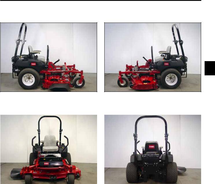
Kohler EFI Product Shots
2
Fig 005 |
DSC-2865b |
|
Fig 007 |
DSC-2867a |
|
|
|
|
|
|
|
|
|
|
Fig 006 |
DSC-2866a |
Fig 008 |
DSC-2868a |
Z Master 500 Gas Series Service Manual |
2-3 |
SPECIFICATIONS
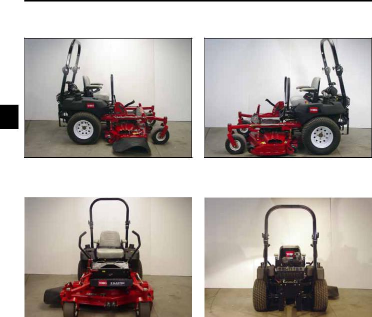
Kohler Gas Product Shots
2
Fig 009 |
DSC-2870a |
|
Fig 011 |
DSC-2875a |
|
|
|
|
|
|
|
|
|
|
Fig 010 |
DSC-2869a |
Fig 012 |
DSC-2874a |
2-4 |
Z Master 500 Gas Series Service Manual |
SPECIFICATIONS
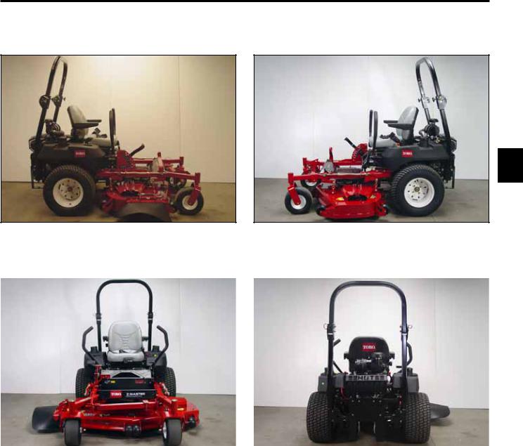
Kawasaki Gas Product Shots
2
Fig 013 |
DSC-2877a |
|
Fig 015 |
DSC-2880a |
|
|
|
|
|
|
|
|
|
|
Fig 014 |
DSC-2879a |
Fig 016 |
DSC-2882a |
Z Master 500 Gas Series Service Manual |
2-5 |

SPECIFICATIONS
Engines
|
|
Output |
Make |
High Idle |
Low Idle |
Charging Coil |
|
|
|
20 HP (14.9kW) |
Kohler |
3750 |
+50/-100 RPM |
1500 RPM |
15 AMP |
|
|
|
OHV V-Twin |
|
|
|
|
|
|
|
Air Cooled |
|
|
|
|
|
|
|
|
|
|
|
|
|
|
23 HP (17.2 kW) |
Kohler |
3750 |
+50/-100 RPM |
1500 RPM |
15 AMP |
|
|
|
OHV V-Twin |
|
|
|
|
2 |
|
|
Air Cooled |
|
|
|
|
|
|
|
|
|
|
|
|
|
25 HP (18.6 kW) |
Kawasaki |
3750 |
+50/-100 RPM |
1500 RPM |
13 AMP |
|
|
|
|
OHV V-Twin |
3000 |
+ 100 Int’l |
|
|
|
|
|
|
|
|||
|
|
|
Air Cooled |
|
|
|
|
|
|
|
|
|
|
|
|
|
|
27 HP (20.1 kW) |
Kohler |
3750 |
+50/-100 RPM |
1500 RPM |
15 AMP |
|
|
|
OHV V-Twin |
|
|
|
|
|
|
|
Air Cooled |
|
|
|
|
|
|
|
|
|
|
|
|
|
|
27 HP (20.1 kW) |
Kawasaki |
3750 |
+50/-100 RPM |
2250 RPM |
30 AMP |
|
|
|
OHV V-Twin |
|
|
|
|
|
|
|
Liquid Cooled |
|
|
|
|
|
|
|
|
|
|
|
|
|
|
28 HP (20.8 kW) |
Kohler |
3750 |
+50/-100 RPM |
1500 RPM |
25 AMP |
|
|
|
OHV V-Twin |
|
|
|
|
|
|
|
EFI Air-Cooled |
|
|
|
|
|
|
|
|
|
|
|
|
2-6 |
Z Master 500 Gas Series Service Manual |

SPECIFICATIONS
Dimensions and Weight
|
|
|
|
|
ROPS Height |
|
|
Width |
|
|
|
|||
|
|
|
|
|
|
|
|
|
|
|
|
|
|
|
Model |
|
|
Weight |
|
Folded |
Upright |
|
|
Deck |
Deflector |
Length |
|
|
|
23 hp Kohler/52” TF Deck |
1140 lbs |
|
53” |
72” |
|
|
53.7” |
68” |
79.5” |
|
|
|||
|
|
|
(517kg) |
|
(134cm) |
(183cm) |
|
(136cm) |
(173cm) |
(202cm) |
|
|
||
23 hp Kohler/60” TF Deck |
1215 lbs |
|
53” |
72” |
|
|
61.7” |
76” |
81.5” |
|
|
|||
|
|
|
(551kg) |
|
(134cm) |
(183cm) |
|
(157cm) |
(193cm) |
(207cm) |
|
|
||
25 hp Kawasaki/60” TF Deck |
1215 lbs |
|
53” |
72” |
|
|
61.7” |
76” |
81.5” |
|
|
|||
|
|
|
(551kg) |
|
(134cm) |
(183cm) |
|
(157cm) |
(193cm) |
(207cm) |
|
2 |
||
27 hp Kohler/52” TF Deck |
1176 lbs |
|
53” |
72” |
|
|
53.7” |
68” |
79.5” |
|
||||
|
|
|
(533kg) |
|
(134cm) |
(183cm) |
|
(136cm) |
(173cm) |
(202cm) |
|
|||
|
|
|
|
|||||||||||
27 hp Kohler/60” TF Deck |
1215 lbs |
|
53” |
72” |
|
|
61.7” |
76” |
81.5” |
|
|
|||
|
|
|
(551kg) |
|
(134cm) |
(183cm) |
|
(157cm) |
(193cm) |
(207cm) |
|
|
||
27 hp Kohler/72” TF Deck |
1280 lbs |
|
53” |
72” |
|
|
73.6” |
88” |
84.5” |
|
|
|||
|
|
|
(583kg) |
|
(134cm) |
(183cm) |
|
(187cm) |
(223cm) |
(215cm) |
|
|
||
27 hp Kawasaki LC/60”TF Deck |
1330 lbs |
|
53” |
72” |
|
|
61.7” |
76” |
81.5” |
|
|
|||
|
|
|
(603kg) |
|
(134cm) |
(183cm) |
|
(157cm) |
(193cm) |
(207cm) |
|
|
||
27 hp Kawasaki LC/72”TF Deck |
1395 lbs |
|
53” |
72” |
|
|
73.6” |
88” |
84.5” |
|
|
|||
|
|
|
(633kg) |
|
(134cm) |
(183cm) |
|
(187cm) |
(223cm) |
(215cm) |
|
|
||
28 hp Kohler EFI/60” TF Deck |
1254 lbs |
|
53” |
72” |
|
|
61.7” |
76” |
81.5” |
|
|
|||
|
|
|
(569kg) |
|
(134cm) |
(183cm) |
|
(157cm) |
(193cm) |
(207cm) |
|
|
||
28 hp Kohler EFI/72” TF Deck |
1319 lbs |
|
53” |
72” |
|
|
73.6” |
88” |
84.5” |
|
|
|||
|
|
|
(598kg) |
|
(134cm) |
(183cm) |
|
(187cm) |
(223cm) |
(215cm) |
|
|
||
Construction |
|
|
|
|
|
|
|
|
|
|
|
|
||
|
|
|
|
|
|
|
|
|
|
|
|
|
|
|
Frame Assembly |
Consists of front and rear frames bolted together |
|
|
|
|
|
|
|
|
|||||
|
|
|
|
|
|
|
|
|
|
|
|
|
|
|
Front Frame |
|
Welded 2 x 2 x .188 structural steel tube |
|
|
|
|
|
|
|
|
|
|||
|
|
|
|
|
|
|
|
|
|
|
|
|
|
|
Rear Frame |
|
Welded tube and fabricated steel |
|
|
|
|
|
|
|
|
|
|||
|
|
|
|
|
|
|
|
|
|
|
|
|
|
|
Fuel System |
|
|
|
|
|
|
|
|
|
|
|
|
||
|
|
|
|
|
|
|
|
|
|
|
|
|||
Tanks |
Dual fuel tanks containing large fill necks and vented caps |
|
|
|
|
|
|
|||||||
|
Mounted above the drive wheels |
|
|
|
|
|
|
|
|
|
|
|||
Capacity |
12 gallons (45.4l) [6 gallons per tank] |
|
|
|
|
|
|
|
|
|
||||
|
|
|
|
|
|
|
|
|
|
|
|
|||
Check Valve |
In-line check valves (Selector valve on EFI units) |
|
|
|
|
|
|
|||||||
|
|
|
|
|
|
|
|
|
|
|
|
|
|
|
Fuel Filter |
40 micron, replaceable in-line filter |
|
|
|
|
|
|
|
|
|
|
|||
|
|
|
|
|
|
|
|
|
|
|
|
|
|
|
Z Master 500 Gas Series Service Manual |
2-7 |

SPECIFICATIONS
Traction System
|
|
Hydraulic Pumps |
|
Twin Hydro-Gear BDP/PJ Series variable displacement hydrostatic with shock valves |
|||||||
|
|
Pump Drive |
|
|
|
Self-tensioning belt drive |
|
|
|
||
|
|
Wheel Motors |
|
Twin Parker-Ross Torqmotor™ positive displacement with 1.25 inch heavy duty |
|||||||
|
|
|
|
|
|
|
tapered shafts |
|
|
|
|
|
|
Ground Speeds |
|
Infinitely variable: Forward: |
0 - 10 mph (16.1 km/hr) |
||||||
|
|
|
|
|
|
|
Reverse: |
0 - 6.3 mph (10.1 km/hr) |
|||
|
|
Release Valves |
|
Contained in pumps. Allow unit to be moved without engine running |
|||||||
2 |
|
Hydraulic Fluid |
|
Mobil 1, 15W50 (Synthetic motor oil) |
|||||||
|
|
|
|||||||||
|
|
System Capacity |
|
2.1 quarts (2.0l) |
|
|
|
||||
|
|
Deck Drive |
|
|
|
|
|
|
|||
|
|
|
|
|
|
|
|
||||
|
|
|
|
|
|
||||||
|
|
Clutch |
|
Warner® Electromagnetic “Mag-Stop” with 200 ft-lb. (271 Nm) rating |
|
||||||
|
|
Type |
|
Mule drive from engine to deck |
|
|
|
||||
|
|
Take-Up |
|
Spring-loaded idler system |
|
|
|
||||
|
|
Tires |
|
|
|
|
|
|
|
|
|
|
|
|
|
|
|
|
|
|
|
|
|
|
|
Rear Drive Tires |
|
4-ply with “Turf Master” tread |
|
|
|
||||
|
|
|
|
|
|
|
24” x 12.0” – 12 [Models with 62” or 72” deck] |
|
|
||
|
|
|
|
|
|
|
23” x 9.5” – 12 [Models with 52” deck] |
|
|
||
|
|
Front Caster Tires |
|
4-ply with smooth tread |
|
|
|
||||
|
|
|
|
|
|
|
13” x 6.5” – 6 |
|
|
|
|
|
|
Tire Pressure |
|
13 psi (90 kpa) |
|
|
|
||||
|
|
|
|
|
|
|
|
|
|
|
|
|
|
Electrical System |
|
|
|
||||||
|
|
|
|
|
|
|
|
|
|
|
|
|
|
Voltage |
|
12 volt, negative ground |
|
|
|
|
|||
|
|
|
|
|
|
|
|
|
|
|
|
|
|
Battery Type |
|
BCI group U1 |
|
|
|
|
|||
|
|
Fuses |
|
Blade Type |
|
|
|
|
|||
|
|
|
|
|
|
|
|
|
|
|
|
2-8 |
Z Master 500 Gas Series Service Manual |
|
SPECIFICATIONS |
|
|||
Cutting Decks |
|
|
|
|
|
|
|
|
|
||
Configuration |
Side discharge, mid-mounted rotary with three blades. |
|
|
||
Construction |
7 gauge, high strength 50,000 psi steel, 5-1/2” deep, advanced, super flow system, welded |
|
|
|
|
|
construction. 3/8” steel discharge reinforcement plate doubles as bagger attachment point. |
|
|
||
Discharge |
Right hand as viewed from operator seat. Rubber chute, spring biased down toward |
|
|
|
|
|
operating position. Adjustable flow control baffle. |
|
|
||
Blade Tip Speed |
18,000 + ft/min at high idle |
|
|
|
|
|
152cm mower – 4600.7 m/min @3000 RPM |
|
|
||
Height of Cut |
Adjustable from the seat with range 1.5” – 5” in 1/4” increments (3.8cm - 12.7cm) |
|
|
||
2 |
|||||
Deck Suspension |
Deck suspended from machine by four lift chains, and attached to rear wheel supports by |
|
|
||
|
two struts. |
|
|||
|
|
||||
Belt Covers |
16-gauge, formed steel covers. Attached with swell latches. |
|
|
|
|
Gauge Wheels |
52” Cutting Deck – Five adjustable gauge wheels to reduce scalping: three on front of |
|
|
|
|
|
deck (one on left-hand side and two in center) and two on rear of deck (left and right |
|
|
||
|
sides). Wheels have four adjustment positions. |
|
|
||
|
60”, 72”, and 152cm Cutting Decks – Six adjustable gauge wheels to reduce scalping: four |
|
|
|
|
|
on front of deck (one each left-hand and right-hand sides, and two center) and two on rear |
|
|
||
|
of deck (left and right sides). Wheels have four positions. |
|
|
||
Lubrication Fittings: |
|
|
|
|
|
Front Castor Pivots |
2 removable plugs (1 per side) for periodic lubrication. |
|
|
|
|
Front Castor |
2 fittings (1 per side). |
|
|
|
|
Wheels |
|
|
|
|
|
Lift Assembly |
5 fittings. |
|
|
|
|
Mule Drive Idler |
1 fitting. |
|
|
|
|
Brake Arms |
2 fittings (1 per side). |
|
|
|
|
Rear Deck Struts |
2 fittings (1 per side). |
|
|
|
|
Deck Spindles |
3 fittings (1 per spindle). |
|
|
|
|
Hydraulic Pump |
1 fitting. |
|
|
|
|
Drive Tensioner |
|
|
|
|
|
Z Master 500 Gas Series Service Manual |
2-9 |
SPECIFICATIONS
General Specifications
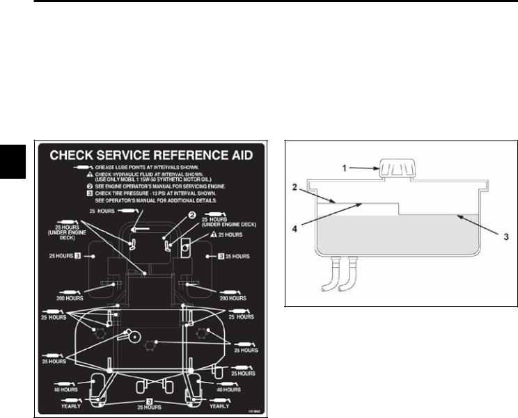
Greasing and Lubrication:
Grease: |
No. 2 general purpose lithium base or molybdenum grease. |
|
|
Where to Add Grease: |
See Check Service Reference Aid decal below (Fig. 017). |
|
|
2
|
|
Fig 018 |
fig. 55 m-5615 |
1. |
Cap |
3. |
Cold fluid level - full |
2. |
Baffle |
4. |
Hot fluid level - full |
Fig 017 |
fig. 50 decal |
|
|
Hydraulic System Oil Capacity: |
4 quarts (3.8 l) |
|
|
Fluid Type: |
Mobil 1 15w50 synthetic motor oil or equivalent synthetic oil |
|
|
Fluid Level: |
Check the fluid level while the fluid is warm. The fluid should be between cold |
|
and hot. |
|
Note: The fluid level should be to the top of the hot level of the baffle, |
|
when the fluid is hot (Fig. 018 above). |
2-10 |
Z Master 500 Gas Series Service Manual |
SPECIFICATIONS
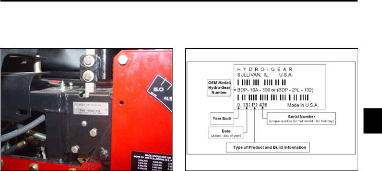
Model and Serial Number Location |
The unit model and serial number plate is located on the right hand side of |
|
the unit, below the right side motion control lever (Fig. 019). |
2
Fig 019 DSC-2351 Fig 020 configuration
Engine Model and Serial Number |
Consult the appropriate engine manufacture’s service literature for the |
Identification: |
location and translation of the engine model and serial number information. |
|
|
Hydrostatic Pumps Model and Serial |
The label above (Fig. 020), is located on the pump housing. It identifies the |
Number: |
model and configuration of the BDP pump. |
|
|
Available Service Manuals
Hydrostatic Pumps: |
Hydro-Gear BDP-10A/16A/21L – Service and Repair Manual |
|
Form # 492-4789 |
Wheel Motors: |
Parker/Ross Wheel Motor Service Manual |
|
Form # 492-4753 |
Engine: |
Engine manufacturer |
Hydraulic Troubleshooting: |
Interactive hydraulic troubleshooting and failure analysis on compact disk |
|
Form #492-4777 |
Electrical Troubleshooting: |
Interactive electrical troubleshooting and wiring diagrams on compact disk |
|
Form #492-9143 |
Z Master 500 Gas Series Service Manual |
2-11 |
SPECIFICATIONS
Torque Specifications |
Fastener Identification |
Recommended fastener torque values are listed in the following tables. For critical applications, as determined by Toro, either the recommended torque or a torque that is unique to the application is clearly identified and specified in the service manual.
These torque specifications for the installation and tightening of fasteners shall apply to all fasteners which
2 do not have a specific requirement identified in the service manual. The following factors shall be considered when applying torque: cleanliness of the fastener, use of a thread sealant (Loctite), degree of lubrication on the fastener, presence of a prevailing torque feature, hardness of the surface underneath of the fastener’s head, or similar condition which affects the installation.
As noted in the following tables, torque values should be reduced by 25% for lubricated fasteners to achieve the similar stress as a dry fastener. Torque values may also have to be reduced when the fastener is threaded into aluminum or brass. The specific torque value should be determined based on the aluminum or brass material strength, fastener size, length of thread engagement, etc.
The standard method of verifying torque shall be performed by marking a line on the fastener (head or nut) and mating part, then back off fastener 1/4 of a turn. Measure the torque required to tighten the fastener until the lines match up.
|
Figure A |
|
|
||
Inch Series Bolts and Screws |
||
|
|
|
(A) Grade 1 |
|
(C) Grade 8 |
(B) Grade 5 |
|
|
|
|
|
|
|
|
|
|
|
Figure B
Metric Bolts and Screws
(A) Class 8.8 |
(B) Class 10.9 |
|
|
2-12 |
Z Master 500 Gas Series Service Manual |

SPECIFICATIONS
Standard Torque for Dry, Zinc Plated, and Steel Fasteners (Inch Series)
|
Grade 1, 5, & |
SAE Grade 1 Bolts, Screws, |
SAE Grade 5 Bolts, Screws, |
SAE Grade 8 Bolts, Screws, |
|
|
||||||||||||
Thread Size |
8 with Thin |
Studs, & Sems with Regular |
Studs, & Sems with Regular |
Studs, & Sems with Regular |
|
|
||||||||||||
Height Nuts |
Height Nuts (SAE J995 |
Height Nuts (SAE J995 |
Height Nuts (SAE J995 |
|
|
|||||||||||||
|
|
|
||||||||||||||||
|
|
|
Grade 2 or Stronger Nuts) |
Grade 2 or Stronger Nuts) |
Grade 2 or Stronger Nuts) |
|
|
|||||||||||
|
In-lb |
|
In-lb |
|
N-cm |
|
In-lb |
|
N-cm |
|
In-lb |
|
N-cm |
|
|
|
|
|
|
|
|
|
|
|
|
|
|
|
|
|
|
|
|
|
|
|
|
# 6 - 32 UNC |
10 |
± 2 |
13 |
± 2 |
147 |
± 23 |
15 |
± 2 |
170 |
± 20 |
23 |
± 2 |
260 |
± |
20 |
|
|
|
# 6 - 40 UNF |
17 |
± 2 |
190 |
± 20 |
25 |
± 2 |
280 |
± |
20 |
|
|
|||||||
|
|
|
|
|
|
|
|
|||||||||||
# 8 - 32 UNC |
|
|
|
|
|
|
29 |
± 3 |
330 |
± 30 |
41 |
± 4 |
460 |
± |
45 |
|
|
|
13 |
± 2 |
25 |
± 5 |
282 |
± 30 |
2 |
||||||||||||
# 8 - 36 UNF |
31 ± 3 |
350 ± 30 |
43 |
± 4 |
31 ± 3 |
|
||||||||||||
|
|
|
|
|
|
|
||||||||||||
# 10 - 24 UNC |
18 |
± 2 |
30 |
± 5 |
339 |
± 56 |
42 |
± 4 |
475 |
± 45 |
60 |
± 6 |
674 |
± 70 |
|
|||
|
||||||||||||||||||
#10 - 32 UNF |
48 |
± 4 |
540 |
± 45 |
68 |
± 6 |
765 |
± 70 |
|
|
||||||||
|
|
|
|
|
|
|
|
|||||||||||
1/4 - 20 UNC |
48 |
± 7 |
53 |
± 7 |
599 |
± 79 |
100 |
± 10 |
1125 ± 100 |
140 |
± 15 |
1580 |
± 170 |
|
|
|||
1/4 - 28 UNF |
53 |
± 7 |
65 ± 10 |
734 ± 113 |
115 ± 10 |
1300 |
± 100 |
160 |
± 15 |
1800 |
± 170 |
|
|
|||||
5/16 - 18 UNC |
115 ± 15 |
105 |
± 17 |
1186 ± 169 |
200 |
± 25 |
2250 |
± 280 |
300 |
± 30 |
3390 |
± 340 |
|
|
||||
5/16 - 24 UNF |
138 |
± 17 |
128 |
± 17 |
1446 |
± 192 |
225 |
± 25 |
2540 |
± 280 |
325 |
± 30 |
3670 |
± 340 |
|
|
||
|
ft-lb |
ft-lb |
N-m |
ft-lb |
N-m |
ft-lb |
N-m |
|
|
|||||||||
3/8 - 16 UNC |
16 |
± 2 |
16 |
± 2 |
22 |
± 3 |
30 |
± 3 |
41 |
± 4 |
43 |
± 4 |
58 |
± 5 |
|
|
||
3/8 - 24 UNF |
17 |
± 2 |
18 |
± 2 |
24 |
± 3 |
35 |
± 3 |
47 |
± 4 |
50 |
± 4 |
68 |
± 5 |
|
|
||
7/16 - 14 UNC |
27 |
± 3 |
27 |
± 3 |
37 |
± 4 |
50 |
± 5 |
68 |
± 7 |
70 |
± 7 |
68 |
± 9 |
|
|
||
7/16 - 20 UNF |
29 |
± 3 |
29 |
± 3 |
39 |
± 4 |
55 |
± 5 |
75 |
± 7 |
77 |
± 7 |
104 ± 9 |
|
|
|||
1/2 - 13 UNC |
30 |
± 3 |
48 |
± 7 |
65 |
± 9 |
75 |
± 8 |
102 ± 11 |
105 |
± 10 |
142 |
± 14 |
|
|
|||
1/2 - 20 UNF |
32 |
± 3 |
53 |
± 7 |
72 |
± 9 |
85 |
± 8 |
115 |
± 11 |
120 |
± 10 |
163 |
± 14 |
|
|
||
5/8 - 11 UNC |
65 ± 10 |
88 ± 12 |
119 ± 16 |
150 |
± 15 |
203 |
± 20 |
210 |
± 20 |
285 |
± 27 |
|
|
|||||
5/8 - 18 UNF |
75 ± 10 |
95 ± 15 |
129 |
± 20 |
170 |
± 15 |
230 |
± 20 |
240 |
± 20 |
325 |
± 27 |
|
|
||||
3/4 - 10 UNC |
93 ± 12 |
140 |
± 20 |
190 |
± 27 |
265 |
± 25 |
359 |
± 34 |
374 |
± 35 |
508 |
± 47 |
|
|
|||
3/4 - 16 UNF |
115 ± 15 |
165 |
± 25 |
224 |
± 34 |
300 |
± 25 |
407 |
± 34 |
420 |
± 35 |
569 |
± 47 |
|
|
|||
7/8 - 9 UNC |
140 |
± 20 |
225 |
± 25 |
305 |
± 34 |
430 |
± 45 |
583 |
± 61 |
600 |
± 60 |
813 |
± 81 |
|
|
||
7/8 - 14 UNF |
155 |
± 25 |
260 |
± 30 |
353 |
± 41 |
475 |
± 45 |
644 |
± 61 |
660 |
± 60 |
895 |
± 81 |
|
|
||
|
|
|
|
|
|
|
|
|
|
|
|
|
|
|
|
|
|
|
Note: Reduce torque values listed in the table above by 25% for lubricated fasteners. Lubricated fasteners are defined as threads coated with a lubricant such as oil, graphite, or thread sealant such as Loctite.
Note: Torque values may have to be reduced when installing fasteners into threaded aluminum or brass. The specific torque value should be determined based on the fastener size, the aluminum or base material strength, length of thread engagement, etc.
Note: The nominal torque values listed above for Grade 5 and 8 fasteners are based on 75% of the minimum proof load specified in SAE J429. The tolerance is approximately ± 10% of the nominal torque value. Thin height nuts include jam nuts.
Z Master 500 Gas Series Service Manual |
2-13 |

SPECIFICATIONS
Standard Torque for Dry, Zinc, and Steel Fasteners (Metric Fasteners)
|
|
Thread Size |
Class 8.8 Bolts, Screws, and Studs with |
Class 10.9 Bolts, Screws, and Studs with |
|||||||||
|
|
|
Regular Height Nuts |
|
Regular Height Nuts ( |
|
|||||||
|
|
|
|
(Class 8 or Strong Nuts) |
|
Class 10 or Strong Nuts) |
|||||||
|
|
M5 X 0.8 |
57 ± 5 in-lb |
640 |
± 60 N-cm |
78 ± 7 in-lb |
885 ± 80 N-cm |
||||||
|
|
M6 X 1.0 |
96 ± 9 in-lb |
1018 |
± 100 N-cm |
133 ± 13 in-lb |
1500 ± 150 N-cm |
||||||
|
|
M8 X 1.25 |
19 |
± 2 ft-lb |
26 |
± 3 N-m |
27 |
± 2 ft-lb |
36 |
± |
3 N-m |
||
|
|
M10 X 1.5 |
38 |
± 4 ft-lb |
52 |
± 5 N-m |
53 |
± 5 ft-lb |
72 |
± |
7 N-m |
||
|
|
M12 X 1.75 |
66 |
± 7 ft-lb |
90 |
± 10 N-m |
92 |
± 9 ft-lb |
125 |
± |
12 N-m |
||
2 |
|||||||||||||
|
M16 X 2.0 |
166 |
± 15 ft-lb |
225 |
± 20 N-m |
229 |
± 22 ft-lb |
310 |
± |
30 N-m |
|||
|
M20 X 2.5 |
325 |
± 33 ft-lb |
440 |
± 45 N-m |
450 |
± 37 ft-lb |
610 |
± |
50 N-m |
|||
|
|
|
|
|
|
|
|
|
|
|
|
|
|
Note: Reduce torque values listed in the table above by 25% for lubricated fasteners. Lubricated fasteners are defined as threads coated with a lubricant such as oil, graphite, or thread sealant such as Loctite.
Note: Torque values may have to be reduced when installing fasteners into threaded aluminum or brass. The specific torque value should be determined based on the fastener size, the aluminum or base material strength, length of thread engagement, etc.
Note: The nominal torque values listed above are based on 75% of the minimum proof load specified in SAE J1199. The tolerance is approximately ± 10% of the nominal torque value. Thin height nuts include jam nuts.
2-14 |
Z Master 500 Gas Series Service Manual |
SPECIFICATIONS
Other Torque Specifications
SAE Grade 8 Steel Set Screws
Thread Size |
Recommended Torque |
||
|
|
||
Square Head |
Hex Socket |
||
|
|||
|
|
|
|
1/4 - 20 UNC |
140 ± 20 in-lb |
73 ± 12 in-lb |
|
|
|
|
|
5/16 - 18 UNC |
215 ± 35 in-lb |
145 ± 20 in-lb |
|
|
|
|
|
3/8 - 16 UNC |
35 ± 10 ft-lb |
18 ± 3 ft-lb |
|
|
|
|
|
1/2 - 13 UNC |
75 ± 15 ft-lb |
50 ± 10 ft-lb |
|
|
|
|
|
Wheel Bolts and Lug Nuts
Thread Size |
Recommended Torque** |
|
|
|
|
|
|
|
|
7/16 - 20 UNF |
65 ± 10 ft-lb |
88 ± 14 N-m |
|
|
Grade 5 |
|
|
||
|
|
|
|
|
1/2 - 20 UNF |
80 ± 10 ft-lb |
108 ± 14 N-m |
|
|
Grade 5 |
|
|
||
|
|
|
2 |
|
M12 X 1.25 |
80 ± 10 ft-lb |
108 ± 14 N-m |
|
|
Class 8.8 |
|
|||
|
|
|
|
|
M12 X 1.5 |
80 ± 10 ft-lb |
108 ± 14 N-m |
|
|
Class 8.8 |
|
|
||
|
|
|
|
|
|
|
|
|
|
** For steel wheels and non-lubricated fasteners.
Thread Cutting Screws
(Zinc Plated Steel)
Type 1, Type 23, or Type F
Thread Size |
Baseline Torque* |
|
|
|
|
No. 6 - 32 UNC |
20 |
± 5 in-lb |
|
|
|
No. 8 - 32 UNC |
30 |
± 5 in-lb |
|
|
|
No.10 - 24 UNC |
38 |
± 7 in-lb |
|
|
|
1/4 - 20 UNC |
85 ± 15 in-lb |
|
|
|
|
5/16 - 18 UNC |
110 |
± 20 in-lb |
|
|
|
3/8 - 16 UNC |
200 ± 100 in-lb |
|
|
|
|
Thread Cutting Screws
(Zinc Plated Steel)
Thread |
Threads per Inch |
Baseline Torque* |
||
|
|
|||
Size |
Type A |
Type B |
||
|
||||
|
|
|||
No. 6 |
18 |
20 |
20 ± 5 in-lb |
|
No. 8 |
15 |
18 |
30 ± 5 in-lb |
|
No. 10 |
12 |
16 |
38 ± 7 in-lb |
|
No. 12 |
11 |
14 |
85 ± 15 in-lb |
|
* Hole size, material strength, material thickness and finish must be considered when determining specific torque values. All torque values are based on nonlubricated fasteners.
Conversion Factors |
|
in-lb X 11.2985 - N-cm |
N-cm X - 0.08851 = in-lb |
ft-lb X 1.3558 = N-m |
N-cm X 0.73776 - ft-lb |
Z Master 500 Gas Series Service Manual |
2-15 |

SPECIFICATIONS
Equivalents and Conversions
Decimal and Millimeter Equivalents
|
|
Fractions |
Decimals |
mm |
Fractions |
|
Decimals |
mm |
|
|
|
|
|
|
|
|
|
|
|
1/64 |
0.015625 |
0.397 |
|
33/64 |
0.515625 |
13.097 |
|
|
1/32 |
0.03125 |
0.794 |
16/32 |
|
0.53125 |
13.484 |
|
|
3/64 |
0.046875 |
1.191 |
|
35/64 |
0.546875 |
13.891 |
|
|
1/16 |
0.0625 |
1.588 |
9/16 |
|
0.5625 |
14.288 |
2 |
|
5/64 |
0.078125 |
1.984 |
|
37/64 |
0.578125 |
14.684 |
|
3/32 |
0.9375 |
2.381 |
19/32 |
|
0.59375 |
15.081 |
|
|
1/8 |
0.1250 |
3.175 |
5/8 |
|
0.6250 |
15.875 |
|
|
|
|||||||
|
|
9/64 |
0.140625 |
3.572 |
|
41/64 |
0.640625 |
16.272 |
|
|
5/32 |
0.15625 |
3.969 |
21/32 |
|
0.65625 |
16.669 |
|
|
11/64 |
0.171875 |
4.366 |
|
43/64 |
0.671875 |
17.066 |
|
|
3/16 |
0.1875 |
4.762 |
11/16 |
|
0.6875 |
17.462 |
|
|
13/64 |
0.203125 |
5.159 |
|
45/64 |
0.703125 |
17.859 |
|
|
7/32 |
0.21875 |
5.556 |
23/32 |
|
0.71875 |
18.256 |
|
|
15/64 |
0.234375 |
5.953 |
|
47/64 |
0.734375 |
18.653 |
|
|
1/4 |
0.2500 |
6.350 |
3/4 |
|
0.7500 |
19.050 |
|
|
17/64 |
0.265625 |
6.747 |
|
49/64 |
0.765625 |
19.447 |
|
|
9/32 |
0.28125 |
7.144 |
25/32 |
|
0.78125 |
19.844 |
|
|
19/64 |
0.296875 |
7.541 |
|
51/64 |
0.796875 |
20.241 |
|
|
5/16 |
0.3125 |
7.541 |
13/16 |
|
0.8125 |
20.638 |
|
|
21/64 |
0.328125 |
8.334 |
|
53/64 |
0.828125 |
21.034 |
|
|
11/32 |
0.34375 |
8.731 |
27/32 |
|
0.84375 |
21.431 |
|
|
23/64 |
0.359375 |
9.128 |
|
55/64 |
0.859375 |
21.828 |
|
|
3/8 |
0.3750 |
9.525 |
7/8 |
|
0.8750 |
22.225 |
|
|
25/64 |
0.390625 |
9.922 |
|
57/64 |
0.890625 |
22.622 |
|
|
13/32 |
0.40625 |
10.319 |
29/32 |
|
0.90625 |
23.019 |
|
|
27/64 |
0.421875 |
10.716 |
|
59/64 |
0.921875 |
23.416 |
|
|
7/16 |
0.4375 |
11.112 |
15/16 |
|
0.9375 |
23.812 |
|
|
29/64 |
0.453125 |
11.509 |
|
61/64 |
0.953125 |
24.209 |
|
|
15/32 |
0.46875 |
11.906 |
31/32 |
|
0.96875 |
24.606 |
|
|
31/64 |
0.484375 |
12.303 |
|
63/64 |
0.984375 |
25.003 |
|
|
1/2 |
0.5000 |
12.700 |
1 |
|
1.000 |
25.400 |
|
|
1 mm = 0.03937 in. |
|
|
0.001 in. = 0.0254 mm |
|
||
2-16 |
Z Master 500 Gas Series Service Manual |

|
|
|
SPECIFICATIONS |
|
||||
|
|
U.S. to Metric Conversions |
|
|
|
|
|
|
|
|
|
|
|
|
|
||
|
|
To Convert |
Into |
Multiply By |
|
|
|
|
|
|
|
|
|
|
|
|
|
|
|
Miles |
Kilometers |
|
1.609 |
|
|
|
|
|
Yards |
Meters |
|
0.9144 |
|
|
|
|
Linear |
Feet |
Meters |
|
0.3048 |
|
|
|
|
Feet |
Centimeters |
|
30.48 |
|
|
|
|
|
Measurement |
Inches |
Meters |
|
0.0254 |
|
|
|
|
|
Inches |
Centimeters |
|
|
|
|
|
|
|
|
2.54 |
|
|
|
||
|
|
Inches |
Millimeters |
|
|
|
|
|
|
|
|
25.4 |
|
|
|
||
|
|
|
|
|
|
|
|
|
|
|
|
|
|
|
2 |
||
|
|
Square Miles |
Square Kilometers |
|
2.59 |
|
|
|
|
Area |
Square Feet |
Square Meters |
|
0.0929 |
|
|
|
|
Square Inches |
Square Centimeters |
|
|
|
|||
|
|
|
6.452 |
|
|
|
||
|
|
Acre |
Hectare |
|
0.4047 |
|
|
|
|
|
Cubic Yards |
Cubic Meters |
|
0.7646 |
|
|
|
|
Volume |
Cubic Feet |
Cubic Meters |
|
0.02832 |
|
|
|
|
|
Cubic Inches |
Cubic Centimeters |
|
16.39 |
|
|
|
|
|
Tons (Short) |
Metric Tons |
|
0.9078 |
|
|
|
|
Weight |
Pounds |
Kilograms |
|
0.4536 |
|
|
|
|
|
Ounces |
Grams |
|
28.3495 |
|
|
|
|
Pressure |
Pounds/Sq. In. |
Kilopascal |
|
6.895 |
|
|
|
|
|
|
|
|
|
|
|
|
|
|
Foot-pounds |
Newton-Meters |
|
1.356 |
|
|
|
|
Work |
Foot-pounds |
Kilogram-Meters |
|
0.1383 |
|
|
|
|
|
Inch-pounds |
Kilogram-Centimeters |
|
1.152144 |
|
|
|
|
Liquid Volume |
Quarts |
Liters |
|
0.9463 |
|
|
|
|
Gallons |
Liters |
|
3.785 |
|
|
|
|
|
|
|
|
|
|
|||
|
Liquid Flows |
Gallons/Minute |
Liters/Minute |
|
3.785 |
|
|
|
|
|
|
|
|
|
|
|
|
|
Temperature |
Fahrenheit |
Celsius |
1. |
Subtract 32° |
|
|
|
|
|
|
2. |
Multiply by 5/9 |
|
|
|
|
|
|
|
|
|
|
|||
Z Master 500 Gas Series Service Manual |
2-17 |

SPECIFICATIONS
2
THIS PAGE INTENTIONALLY LEFT BLANK.
2-18 |
Z Master 500 Gas Series Service Manual |

CHASSIS
Safety Information . . . . . . . . . 1
Specifications . . . . . . . . . . . 2
Chassis . . . . . . . . . . . . . . 3
Hydraulic System . . . . . . . . . 4
Engine . . . . . . . . . . . . . . . 5
Electrical . . . . . . . . . . . . . . 6
Mower Decks/PTO . . . . . . . . . 7
Z Master 500 Gas Series Service Manual |
3-1 |

CHASSIS
Caster Fork Assembly Removal
1.Raise the front of the unit off the ground, allowing enough clearance to remove the castor fork from the bottom of the hub.
2.With a hammer and chisel, remove the top grease cap (Fig. 021).
3
Fig 021 |
mvc-1531 |
4.Remove the Belleville washers and caster fork and wheel assembly (Fig. 023).
Fig 023 |
DSC-1533 |
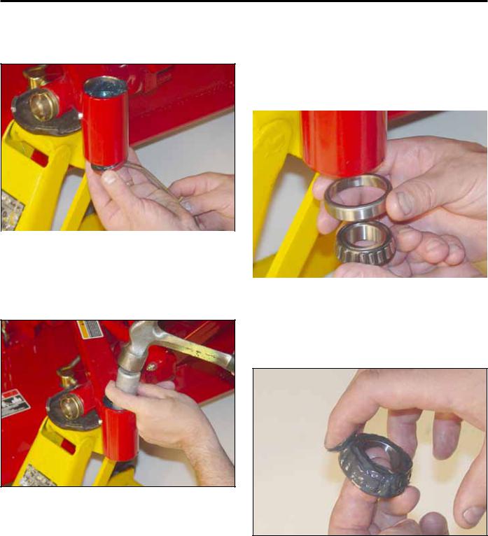
Replacing the Caster Bearings
1. Remove the top tapered roller bearing (Fig. 024).
3. Remove the locknut (Fig. 022).
Fig 024 |
DSC-1534 |
Fig 022 |
DSC-1532 |
3-2 |
Z Master 500 Gas Series Service Manual |
CHASSIS
2.Remove bottom seal and tapered roller bearing (Fig. 025).
4.With a driver and hammer, install new tapered bearing cups. The bearing cups are tapered; make sure the tapered/thicker end of the cup is installed inward for the top and bottom end (Fig. 027). Tap the bearing cups in until they seat against the step in the caster hub.
|
|
|
|
|
|
|
|
|
|
|
3 |
Fig 025 |
DSC-1535 |
|
|
||
|
|
|
|
|
|
3.With a driver and hammer, remove both the bottom and top tapered bearing cups (Fig. 026).
Fig 027 |
DSC-1537 |
5.Pack the upper and lower tapered bearings prior to installation (Fig. 028).
Fig 026 |
DSC-1536 |
Fig 028 |
DSC-1539 |
Z Master 500 Gas Series Service Manual |
3-3 |
 Loading...