


 Loading...
400XT Series Tractor
Service
Manual

ABOUT THIS MANUAL
This service manual was written expressly for Toro service technicians. The Toro Company has made every effort to make the information in this manual complete and correct.
Basic shop safety knowledge and mechanical/electrical skills are assumed. The Table of
Contents lists the systems and the related topics covered in this manual.
For additional information on the electrical system, please refer to the Toro Electrical
Demystification Guide (492-4404). For service information on drive systems, please refer to the Hydro-Gear (330-3000) service manual. For information information specific to the engines used on this unit, refer to the appropriate engine manufacturer’s service and repair instructions.
Tractor model years 2003 - 2004 are covered in this manual. The manual may also be specified for use on later model products.
The hydrostatic transaxle is a sophisticated piece of machinery. Maintain strict cleanliness control during all stages of service and repair. Cover or cap all hose ends and fittings whenever they are exposed. Even a small amount of dirt or other contamination can severely damage the system.
We are hopeful that you will find this manual a valuable addition to your service shop. If you have questions or comments regarding this manual, please contact us at the following address:
The Toro Company
Consumer Service Department
8111 Lyndale Avenue South
Bloomington, MN 55420-1196
The Toro Company reserves the right to change product specifications or this manual without notice.
Copyright© All Rights Reserved
©2003 The Toro Company

TABLE OF CONTENTS
SPECIFICATIONS |
|
|
General Information . . . . . . . . . . . . . . . . . . . . . . . . . . . . . . . . . . . . . . . . . . . . . . . . |
.1 - 1 |
|
Think Safety First . . . . . . . . . . . . . . . . . . . . . . . . . . . . . . . . . . . . . . . . . . . . . . . . . . |
.1 |
- 1 |
General Specifications . . . . . . . . . . . . . . . . . . . . . . . . . . . . . . . . . . . . . . . . . . . . . . |
.1 - 2 |
|
Hydrostatic Transaxle . . . . . . . . . . . . . . . . . . . . . . . . . . . . . . . . . . . . . . . . . . . . . . . |
.1 - 3 |
|
Identification: Hydro-Gear Model 330-3000 Transaxle . . . . . . . . . . . . . . . . . . . . |
.1 - 3 |
|
General Specifications . . . . . . . . . . . . . . . . . . . . . . . . . . . . . . . . . . . . . . . . . . . . . . |
.1 - 3 |
|
Torque Specifications . . . . . . . . . . . . . . . . . . . . . . . . . . . . . . . . . . . . . . . . . . . . . . . |
.1 - 4 |
|
Fastener Identification . . . . . . . . . . . . . . . . . . . . . . . . . . . . . . . . . . . . . . . . . . . . |
.1 - 4 |
|
Standard Torque for Dry, Zinc Plated, and Steel Fasteners (Inch Series) . . . . . . . |
.1 - 5 |
|
Standard Torque for Dry, Zinc, and Steel Fasteners (Metric Fasteners) . . . . . . . . |
.1 - 6 |
|
Other Torque Specifications . . . . . . . . . . . . . . . . . . . . . . . . . . . . . . . . . . . . . . . . . . |
.1 - 7 |
|
SAE Grade 8 Steel Set Screws . . . . . . . . . . . . . . . . . . . . . . . . . . . . . . . . . . . . . |
.1 - 7 |
|
Thread Cutting Screws (Zinc Plated Steel) . . . . . . . . . . . . . . . . . . . . . . . . . . . . |
.1 - 7 |
|
Conversion Factors . . . . . . . . . . . . . . . . . . . . . . . . . . . . . . . . . . . . . . . . . . . . . . |
.1 - 7 |
|
Wheel Bolts and Lug Nuts . . . . . . . . . . . . . . . . . . . . . . . . . . . . . . . . . . . . . . . . . |
.1 - 7 |
|
Thread Cutting Screws (Zinc Plated Steel) . . . . . . . . . . . . . . . . . . . . . . . . . . . . |
.1 - 7 |
|
Equivalents and Conversions . . . . . . . . . . . . . . . . . . . . . . . . . . . . . . . . . . . . . . . . . |
.1 - 8 |
|
Decimal and Millimeter Equivalents . . . . . . . . . . . . . . . . . . . . . . . . . . . . . . . . . . . . |
.1 - 8 |
|
U.S. to Metric Conversions . . . . . . . . . . . . . . . . . . . . . . . . . . . . . . . . . . . . . . . . . . . |
.1 - 9 |
|
CHASSIS |
|
|
Model and Serial Number Location . . . . . . . . . . . . . . . . . . . . . . . . . . . . . . . . . . . . |
.2 - 1 |
|
Greasing and Lubrication . . . . . . . . . . . . . . . . . . . . . . . . . . . . . . . . . . . . . . . . . . . . |
.2 - 1 |
|
Front Wheel Toe-in . . . . . . . . . . . . . . . . . . . . . . . . . . . . . . . . . . . . . . . . . . . . . . . . . |
.2 - 1 |
|
Front Wheel Toe-in Adjustment . . . . . . . . . . . . . . . . . . . . . . . . . . . . . . . . . . . . . . . |
.2 - 2 |
|
Front Wheel and Spindle Removal and Installation . . . . . . . . . . . . . . . . . . . . . . . . |
.2 - 3 |
|
Removal . . . . . . . . . . . . . . . . . . . . . . . . . . . . . . . . . . . . . . . . . . . . . . . . . . . . . . . |
.2 - 3 |
|
Front Axle Removal and Installation . . . . . . . . . . . . . . . . . . . . . . . . . . . . . . . . . . . . |
.2 - 4 |
|
Steering Gear . . . . . . . . . . . . . . . . . . . . . . . . . . . . . . . . . . . . . . . . . . . . . . . . . . . . . |
.2 - 5 |
|
Description . . . . . . . . . . . . . . . . . . . . . . . . . . . . . . . . . . . . . . . . . . . . . . . . . . . . . |
.2 - 5 |
|
Steering Backlash Adjustment . . . . . . . . . . . . . . . . . . . . . . . . . . . . . . . . . . . . . . . . |
.2 - 5 |
|
Steering Gear Shaft Disassembly . . . . . . . . . . . . . . . . . . . . . . . . . . . . . . . . . . . . . . |
.2 - 7 |
|
Steering Gear Assembly . . . . . . . . . . . . . . . . . . . . . . . . . . . . . . . . . . . . . . . . . . . . . |
.2 - 9 |
|
Sector Gear Disassembly . . . . . . . . . . . . . . . . . . . . . . . . . . . . . . . . . . . . . . . . . . . . |
2 - 11 |
|
Sector Gear Assembly . . . . . . . . . . . . . . . . . . . . . . . . . . . . . . . . . . . . . . . . . . . . . . |
2 - 11 |
|
Tilt Steering . . . . . . . . . . . . . . . . . . . . . . . . . . . . . . . . . . . . . . . . . . . . . . . . . . . . . . . |
2 - 12 |
|
Description . . . . . . . . . . . . . . . . . . . . . . . . . . . . . . . . . . . . . . . . . . . . . . . . . . . . . |
2 - 12 |
|
Tilt Steering Disassembly . . . . . . . . . . . . . . . . . . . . . . . . . . . . . . . . . . . . . . . . . . . . |
2 - 13 |
|
Tilt Steering Assembly . . . . . . . . . . . . . . . . . . . . . . . . . . . . . . . . . . . . . . . . . . . . . . |
2 - 13 |
|
Steering Specifications . . . . . . . . . . . . . . . . . . . . . . . . . . . . . . . . . . . . . . . . . . . . . . |
2 - 14 |
|
Hood Removal . . . . . . . . . . . . . . . . . . . . . . . . . . . . . . . . . . . . . . . . . . . . . . . . . . . . |
2 - 15 |
|
Seat and Fender Removal . . . . . . . . . . . . . . . . . . . . . . . . . . . . . . . . . . . . . . . . . . . |
2 - 15 |
|
Gas Tank Removal . . . . . . . . . . . . . . . . . . . . . . . . . . . . . . . . . . . . . . . . . . . . . . . . . |
2 - 16 |
|
Installation . . . . . . . . . . . . . . . . . . . . . . . . . . . . . . . . . . . . . . . . . . . . . . . . . . . . . |
2 - 17 |
|
400XT Series Tractor Service Manual |
iii |

TABLE OF CONTENTS
CHASSIS (cont’d) |
|
Lift Bar Assembly . . . . . . . . . . . . . . . . . . . . . . . . . . . . . . . . . . . . . . . . . . . . . . . . . |
2 - 17 |
Removal . . . . . . . . . . . . . . . . . . . . . . . . . . . . . . . . . . . . . . . . . . . . . . . . . . . . . . |
2 - 17 |
Lift Lever Assembly . . . . . . . . . . . . . . . . . . . . . . . . . . . . . . . . . . . . . . . . . . . . . . . . |
2 - 18 |
Removal . . . . . . . . . . . . . . . . . . . . . . . . . . . . . . . . . . . . . . . . . . . . . . . . . . . . . . |
2 - 18 |
Assembly . . . . . . . . . . . . . . . . . . . . . . . . . . . . . . . . . . . . . . . . . . . . . . . . . . . . . |
2 - 18 |
Lift Arm/Lift Lever Assembly . . . . . . . . . . . . . . . . . . . . . . . . . . . . . . . . . . . . . . . . . |
2 - 19 |
Removal . . . . . . . . . . . . . . . . . . . . . . . . . . . . . . . . . . . . . . . . . . . . . . . . . . . . . . |
2 - 19 |
Installation . . . . . . . . . . . . . . . . . . . . . . . . . . . . . . . . . . . . . . . . . . . . . . . . . . . . . |
2 - 20 |
Electric Lift . . . . . . . . . . . . . . . . . . . . . . . . . . . . . . . . . . . . . . . . . . . . . . . . . . . . . . . |
2 - 21 |
Removal . . . . . . . . . . . . . . . . . . . . . . . . . . . . . . . . . . . . . . . . . . . . . . . . . . . . . . |
2 - 21 |
Installation . . . . . . . . . . . . . . . . . . . . . . . . . . . . . . . . . . . . . . . . . . . . . . . . . . . . . |
2 - 21 |
HYDRO-GEAR TRANSAXLE
Hydro-Gear Hydrostatic Transaxle . . . . . . . . . . . . . . . . . . . . . . . . . . . . . . . . . . . . . 3 - 1
Internal Service . . . . . . . . . . . . . . . . . . . . . . . . . . . . . . . . . . . . . . . . . . . . . . . . . . 3 - 1
Fluid Change . . . . . . . . . . . . . . . . . . . . . . . . . . . . . . . . . . . . . . . . . . . . . . . . . . . . 3 - 1
Transaxle Removal . . . . . . . . . . . . . . . . . . . . . . . . . . . . . . . . . . . . . . . . . . . . . . . . . 3 - 1
Installation - Hydro-Gear Transaxle . . . . . . . . . . . . . . . . . . . . . . . . . . . . . . . . . . 3 - 4
Neutral Adjustment . . . . . . . . . . . . . . . . . . . . . . . . . . . . . . . . . . . . . . . . . . . . . . . . . 3 - 7
Transaxle Purging Procedures . . . . . . . . . . . . . . . . . . . . . . . . . . . . . . . . . . . . . . 3 - 8
Brake . . . . . . . . . . . . . . . . . . . . . . . . . . . . . . . . . . . . . . . . . . . . . . . . . . . . . . . . . . . . 3 - 9
Checking the Brake . . . . . . . . . . . . . . . . . . . . . . . . . . . . . . . . . . . . . . . . . . . . . . . 3 - 9
Brake Adjustment . . . . . . . . . . . . . . . . . . . . . . . . . . . . . . . . . . . . . . . . . . . . . . . . . . 3 - 9
Foot Control Adjustment . . . . . . . . . . . . . . . . . . . . . . . . . . . . . . . . . . . . . . . . . . . . 3 - 10
Traction Belt Replacement . . . . . . . . . . . . . . . . . . . . . . . . . . . . . . . . . . . . . . . . . . 3 - 11
ELECTRICAL SYSTEMS
Electrical Systems . . . . . . . . . . . . . . . . . . . . . . . . . . . . . . . . . . . . . . . . . . . . . . . . . . 4 - 1 Relay . . . . . . . . . . . . . . . . . . . . . . . . . . . . . . . . . . . . . . . . . . . . . . . . . . . . . . . . . . . . 4 - 1
Purpose . . . . . . . . . . . . . . . . . . . . . . . . . . . . . . . . . . . . . . . . . . . . . . . . . . . . . . . . 4 - 1
Location . . . . . . . . . . . . . . . . . . . . . . . . . . . . . . . . . . . . . . . . . . . . . . . . . . . . . . . 4 - 1 How It Works . . . . . . . . . . . . . . . . . . . . . . . . . . . . . . . . . . . . . . . . . . . . . . . . . . . . 4 - 1 Testing . . . . . . . . . . . . . . . . . . . . . . . . . . . . . . . . . . . . . . . . . . . . . . . . . . . . . . . . 4 - 2
Solenoid . . . . . . . . . . . . . . . . . . . . . . . . . . . . . . . . . . . . . . . . . . . . . . . . . . . . . . . . . 4 - 2
Purpose . . . . . . . . . . . . . . . . . . . . . . . . . . . . . . . . . . . . . . . . . . . . . . . . . . . . . . . . 4 - 2 Location . . . . . . . . . . . . . . . . . . . . . . . . . . . . . . . . . . . . . . . . . . . . . . . . . . . . . . . 4 - 3
How it Works . . . . . . . . . . . . . . . . . . . . . . . . . . . . . . . . . . . . . . . . . . . . . . . . . . . . 4 - 3
Testing . . . . . . . . . . . . . . . . . . . . . . . . . . . . . . . . . . . . . . . . . . . . . . . . . . . . . . . . 4 - 3
iv |
400XT Series Tractor Service Manual |

TABLE OF CONTENTS
ELECTRICAL SYSTEMS (con’d)
Ignition Switch . . . . . . . . . . . . . . . . . . . . . . . . . . . . . . . . . . . . . . . . . . . . . . . . . . . . . .4 - 4
Purpose . . . . . . . . . . . . . . . . . . . . . . . . . . . . . . . . . . . . . . . . . . . . . . . . . . . . . . . .4 - 4
Location . . . . . . . . . . . . . . . . . . . . . . . . . . . . . . . . . . . . . . . . . . . . . . . . . . . . . . . .4 - 4 How It Works . . . . . . . . . . . . . . . . . . . . . . . . . . . . . . . . . . . . . . . . . . . . . . . . . . . .4 - 4
Testing . . . . . . . . . . . . . . . . . . . . . . . . . . . . . . . . . . . . . . . . . . . . . . . . . . . . . . . . .4 - 5
Electric (PTO) Clutch . . . . . . . . . . . . . . . . . . . . . . . . . . . . . . . . . . . . . . . . . . . . . .4 - 5 Purpose . . . . . . . . . . . . . . . . . . . . . . . . . . . . . . . . . . . . . . . . . . . . . . . . . . . . . . . .4 - 5
Location . . . . . . . . . . . . . . . . . . . . . . . . . . . . . . . . . . . . . . . . . . . . . . . . . . . . . . . .4 - 5
How It Works . . . . . . . . . . . . . . . . . . . . . . . . . . . . . . . . . . . . . . . . . . . . . . . . . . . .4 - 5 Testing . . . . . . . . . . . . . . . . . . . . . . . . . . . . . . . . . . . . . . . . . . . . . . . . . . . . . . . . .4 - 5
Coil Resistance Measurement . . . . . . . . . . . . . . . . . . . . . . . . . . . . . . . . . . . . . . .4 - 5
Measuring Clutch Current Draw . . . . . . . . . . . . . . . . . . . . . . . . . . . . . . . . . . . . . .4 - 6 Clutch Burnishing Procedure . . . . . . . . . . . . . . . . . . . . . . . . . . . . . . . . . . . . . . . .4 - 6
PTO Switch . . . . . . . . . . . . . . . . . . . . . . . . . . . . . . . . . . . . . . . . . . . . . . . . . . . . . . . .4 - 6 Purpose . . . . . . . . . . . . . . . . . . . . . . . . . . . . . . . . . . . . . . . . . . . . . . . . . . . . . . . .4 - 6 Location . . . . . . . . . . . . . . . . . . . . . . . . . . . . . . . . . . . . . . . . . . . . . . . . . . . . . . . .4 - 7
How it Works . . . . . . . . . . . . . . . . . . . . . . . . . . . . . . . . . . . . . . . . . . . . . . . . . . . .4 - 7
Testing . . . . . . . . . . . . . . . . . . . . . . . . . . . . . . . . . . . . . . . . . . . . . . . . . . . . . . . . .4 - 7 Seat Switch . . . . . . . . . . . . . . . . . . . . . . . . . . . . . . . . . . . . . . . . . . . . . . . . . . . . . . . .4 - 7
Purpose . . . . . . . . . . . . . . . . . . . . . . . . . . . . . . . . . . . . . . . . . . . . . . . . . . . . . . . .4 - 7
Location . . . . . . . . . . . . . . . . . . . . . . . . . . . . . . . . . . . . . . . . . . . . . . . . . . . . . . . .4 - 8 How It works . . . . . . . . . . . . . . . . . . . . . . . . . . . . . . . . . . . . . . . . . . . . . . . . . . . . .4 - 8
Testing . . . . . . . . . . . . . . . . . . . . . . . . . . . . . . . . . . . . . . . . . . . . . . . . . . . . . . . . .4 - 8
Hourmeter . . . . . . . . . . . . . . . . . . . . . . . . . . . . . . . . . . . . . . . . . . . . . . . . . . . . . . .4 - 8 Purpose . . . . . . . . . . . . . . . . . . . . . . . . . . . . . . . . . . . . . . . . . . . . . . . . . . . . . . . .4 - 8
Location . . . . . . . . . . . . . . . . . . . . . . . . . . . . . . . . . . . . . . . . . . . . . . . . . . . . . . . .4 - 8
How It Works . . . . . . . . . . . . . . . . . . . . . . . . . . . . . . . . . . . . . . . . . . . . . . . . . . . .4 - 8 Testing . . . . . . . . . . . . . . . . . . . . . . . . . . . . . . . . . . . . . . . . . . . . . . . . . . . . . . . . .4 - 8
Magnet Assembly - Cruise Control . . . . . . . . . . . . . . . . . . . . . . . . . . . . . . . . . . . . . .4 - 9
Purpose . . . . . . . . . . . . . . . . . . . . . . . . . . . . . . . . . . . . . . . . . . . . . . . . . . . . . . . .4 - 9 Location . . . . . . . . . . . . . . . . . . . . . . . . . . . . . . . . . . . . . . . . . . . . . . . . . . . . . . . .4 - 9
How It Works . . . . . . . . . . . . . . . . . . . . . . . . . . . . . . . . . . . . . . . . . . . . . . . . . . . .4 - 9 Testing . . . . . . . . . . . . . . . . . . . . . . . . . . . . . . . . . . . . . . . . . . . . . . . . . . . . . . . . .4 - 9
Switch, Cruise Control . . . . . . . . . . . . . . . . . . . . . . . . . . . . . . . . . . . . . . . . . . . . . . .4 - 9 Purpose . . . . . . . . . . . . . . . . . . . . . . . . . . . . . . . . . . . . . . . . . . . . . . . . . . . . . . . .4 - 9
Location . . . . . . . . . . . . . . . . . . . . . . . . . . . . . . . . . . . . . . . . . . . . . . . . . . . . . . . .4 - 9
How It Works . . . . . . . . . . . . . . . . . . . . . . . . . . . . . . . . . . . . . . . . . . . . . . . . . . . .4 - 9 Testing . . . . . . . . . . . . . . . . . . . . . . . . . . . . . . . . . . . . . . . . . . . . . . . . . . . . . . . .4 - 10
Brake Switch . . . . . . . . . . . . . . . . . . . . . . . . . . . . . . . . . . . . . . . . . . . . . . . . . . . . . .4 - 10
Purpose . . . . . . . . . . . . . . . . . . . . . . . . . . . . . . . . . . . . . . . . . . . . . . . . . . . . . . .4 - 10 Location . . . . . . . . . . . . . . . . . . . . . . . . . . . . . . . . . . . . . . . . . . . . . . . . . . . . . . .4 - 10
How it Works . . . . . . . . . . . . . . . . . . . . . . . . . . . . . . . . . . . . . . . . . . . . . . . . . . .4 - 10 Testing . . . . . . . . . . . . . . . . . . . . . . . . . . . . . . . . . . . . . . . . . . . . . . . . . . . . . . . .4 - 10
400XT Series Tractor Service Manual |
v |

TABLE OF CONTENTS
ELECTRICAL SYSTEMS (con’d)
KeyChoice™ Reverse Operating System . . . . . . . . . . . . . . . . . . . . . . . . . . . . . . . 4 - 11
Testing the Key Choice™ Reverse Operating System - Unactivated . . . . . . . . 4 - 11
Testing the KeyChoice™ Reverse Operating System - Activated . . . . . . . . . . 4 - 11
KeyChoice™ Reverse Operating System Switch . . . . . . . . . . . . . . . . . . . . . . . . . 4 - 13
Purpose . . . . . . . . . . . . . . . . . . . . . . . . . . . . . . . . . . . . . . . . . . . . . . . . . . . . . . . 4 - 13
Location . . . . . . . . . . . . . . . . . . . . . . . . . . . . . . . . . . . . . . . . . . . . . . . . . . . . . . 4 - 13
How It Works . . . . . . . . . . . . . . . . . . . . . . . . . . . . . . . . . . . . . . . . . . . . . . . . . . . 4 - 13
Testing . . . . . . . . . . . . . . . . . . . . . . . . . . . . . . . . . . . . . . . . . . . . . . . . . . . . . . . 4 - 13
Reverse Switch . . . . . . . . . . . . . . . . . . . . . . . . . . . . . . . . . . . . . . . . . . . . . . . . . . . 4 - 14
Purpose . . . . . . . . . . . . . . . . . . . . . . . . . . . . . . . . . . . . . . . . . . . . . . . . . . . . . . . 4 - 14
Location . . . . . . . . . . . . . . . . . . . . . . . . . . . . . . . . . . . . . . . . . . . . . . . . . . . . . . 4 - 14
How It Works . . . . . . . . . . . . . . . . . . . . . . . . . . . . . . . . . . . . . . . . . . . . . . . . . . . 4 - 14
Testing . . . . . . . . . . . . . . . . . . . . . . . . . . . . . . . . . . . . . . . . . . . . . . . . . . . . . . . 4 - 14
Module Low Voltage/KeyChoice™ Reverse Operating System . . . . . . . . . . . . . . 4 - 14
Purpose . . . . . . . . . . . . . . . . . . . . . . . . . . . . . . . . . . . . . . . . . . . . . . . . . . . . . . . 4 - 14
Location . . . . . . . . . . . . . . . . . . . . . . . . . . . . . . . . . . . . . . . . . . . . . . . . . . . . . . 4 - 15
How It Works . . . . . . . . . . . . . . . . . . . . . . . . . . . . . . . . . . . . . . . . . . . . . . . . . . . 4 - 15
Testing - Low Voltage Testing . . . . . . . . . . . . . . . . . . . . . . . . . . . . . . . . . . . . . 4 - 15
KeyChoice™ Reverse Operating System Module . . . . . . . . . . . . . . . . . . . . . . . . 4 - 15
Purpose . . . . . . . . . . . . . . . . . . . . . . . . . . . . . . . . . . . . . . . . . . . . . . . . . . . . . . . 4 - 15
vi |
400XT Series Tractor Service Manual |

SAFETY INFORMATION
General Information
This symbol means WARNING or PERSONAL SAFETY INSTRUCTION - read the instruction because it has to do with your safety. Failure to comply with the instruction may result in personal injury or even death.
This manual is intended as a service and repair manual only. The safety instructions provided herein are for troubleshooting, service, and repair of the 400XT Series tractors. The 400XT Series tractors
tractors and attachment operator’s manuals contain safety information and operating tips for safe operating practices. Operator’s manuals are available through your Toro parts source or:
The Toro Company
Publications Department
8111 Lyndale Avenue South
Bloomington, MN 55420
Think Safety First
Avoid unexpected starting of engine...
Always turn off the engine and disconnect the spark plug wire(s) before cleaning, adjusting, or repair.
Avoid lacerations and amputations...
Stay clear of all moving parts whenever the engine is running. Treat all normally moving parts as if they were moving whenever the engine is running or has the potential to start.
Avoid burns...
Do not touch the engine, muffler, or other components which may increase in temperature during operation, while the unit is running or shortly after it has been running.
Avoid fires and explosions...
Avoid spilling fuel and never smoke while working with any type of fuel or lubricant. Wipe up any spilled fuel or oil immediately. Never remove the fuel cap or add fuel when the engine is running. Always use approved, labeled containers for storing or transporting fuel and lubricants.
Avoid asphyxiation...
Never operate an engine in a confined area without proper ventilation.
Avoid injury from batteries...
Battery acid is poisonous and can cause burns. Avoid contact with skin, eyes, and clothing. Battery gases can explode. Keep cigarettes, sparks, and flames away from the battery.
Avoid injury due to inferior parts...
Use only original equipment parts to ensure that important safety criteria are met.
Avoid injury to bystanders...
Always clear the area of bystanders before starting or testing powered equipment.
Avoid injury due to projectiles...
Always clear the area of sticks, rocks, or any other debris that could be picked up and thrown by the powered equipment.
Avoid modifications...
Never alter or modify any part unless it is a factory approved procedure.
Avoid unsafe operation...
Always test the safety interlock system after making adjustments or repairs on the machine. Refer to the Electrical section in this manual for more information.
400XT Series Tractor Service Manual |
1 - 1 |

SPECIFICATIONS
General Specifications
Item |
Specification |
|
|
|
16 H.P. Kohler OHV Command Single Cylinder |
Engines |
17 H.P. Kawasaki OHV Twin Cylinder |
19 H.P. Kawasaki OHV Twin Cylinder |
|
|
For more information on servicing the engines, contact either Briggs & Stratton or |
|
Kawasaki. |
|
|
RPM Setting, All Models |
High RPM Setting (no load) – 3250 + or -100 RPM |
Construction |
Frame: 2” X 2” X 1/4” Welded Angle Frame |
Fuel Capacity |
3.9 Gallons (14.7 liter) |
Wheel Base |
49.5” (125.7cm) |
Overall Length |
71.0’ (180.3cm) |
Overall Width |
35.5” (90.1cm) without the mower |
Weight |
416XT net weight 530 lbs. (240.4kg) |
417XT net weight 560 lbs. (254kg) |
|
|
419XT net weight 580 lbs. (263kg) |
|
|
Traction System |
Hydro-Gear Transaxle model 330-3000 |
Ground Speed |
Forward - Infinite 0 to 6.8 MPH 90 (10.9 km/hr) |
|
Reverse - Infinite 0 to 3.2 MPH (0 - 4.8 km/hr) |
Steering |
Four (4) position tilt wheel |
|
Turning Radius: 16” (40.6cm) RH and LH |
Tires |
Front: 16 X 6.50 - 8 Super Turf Tread |
|
Rear: 23 X 10.50 - 12 Super Turf Tread |
Tire Pressure |
Front Tires 20 p.s.i (138 kpa) |
|
Rear Tires 20 p.s.i. (138 kpa) |
Attachment Drive |
Electric Clutch, Maintenance Free, No Adjustments |
|
416XT: 15 amp Regulated DC Charging System |
|
Battery Voltage - 12 volt negative ground |
|
Battery Type: BCI Group U1, 260 CCA |
|
417XT: 13 amp Regulated DC Charging |
|
Battery Voltage - 12 volt negative ground |
|
Battery Type: BCI Group U1, 340 CCA |
Electrical System |
417XT: 13 amp Regulated DC Charging |
|
|
|
Battery Voltage – 12 volt negative ground |
|
Battery Type: BCI Group U1, 340 CCA |
|
25 amp, Charge Circuit |
|
30 amp, Main Circuit |
|
10 amp, Light Circuit |
|
10 amp, Dash Circuit |
|
|
1 - 2 |
400XT Series Tractor Service Manual |
SPECIFICATIONS
Hydrostatic Transaxle
Identification:
Hydro-Gear Model 330-3000 Transaxle
330-3000
General Specifications
Lubrication |
SAE 20W-50 API Classification SH/CD Oil |
|||
|
|
|
|
|
Oil Capacity |
3.8 qts. (3.6l) |
|||
|
|
|
|
|
|
|
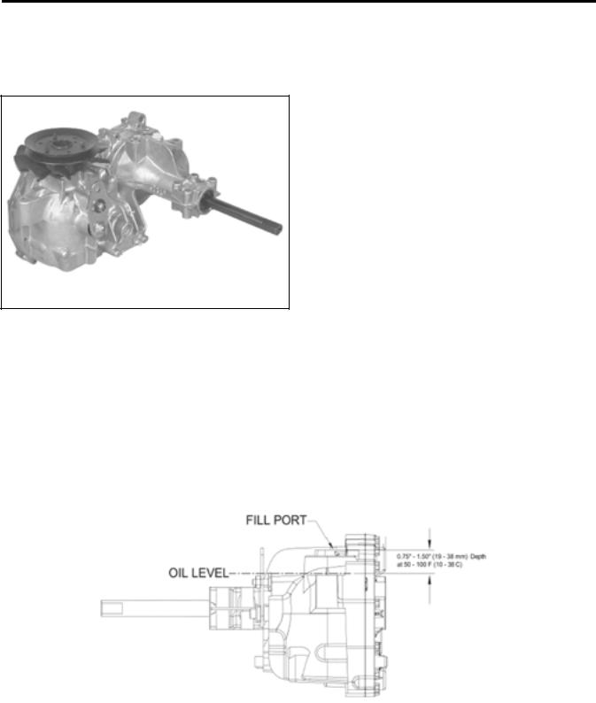
The transaxle is a sealed system and does not require periodic checking. If the |
||
Oil Level |
oil needs to be checked, IT CAN ONLY BE CHECKED COLD. There is a plug |
|||
located on the right rear side of the transaxle. Using a ¼ inch Allen wrench, |
||||
|
|
|||
|
|
slowly remove the plug. Oil level should be to the bottom of the port. |
||
|
|
|
|
|
|
|
|
|
|
400XT Series Tractor Service Manual |
1 - 3 |

SPECIFICATIONS
Torque Specifications |
Fastener Identification |
Recommended fastener torque values are listed in the following tables. For critical applications, as determined by Toro, either the recommended torque or a torque that is unique to the application is clearly identified and specified in the service manual.
These torque specifications for the installation and tightening of fasteners shall apply to all fasteners which do not have a specific requirement identified in the service manual. The following factors shall be considered when applying torque: cleanliness of the fastener, use of a thread sealant (Loctite), degree of lubrication on the fastener, presence of a prevailing torque feature, hardness of the surface underneath of the fastener’s head, or similar condition which affects the installation.
As noted in the following tables, torque values should be reduced by 25% for lubricated fasteners to achieve the similar stress as a dry fastener. Torque values may also have to be reduced when the fastener is threaded into aluminum or brass. The specific torque value should be determined based on the aluminum or brass material strength, fastener size, length of thread engagement, etc.
The standard method of verifying torque shall be performed by marking a line on the fastener (head or nut) and mating part, then back off fastener 1/4 of a turn. Measure the torque required to tighten the fastener until the lines match up.
|
|
|
|
Figure 1 |
|
|
||
Inch Series Bolts and Screws |
||
|
|
|
(A) Grade 1 |
|
(C) Grade 8 |
(B) Grade 5 |
|
|
|
|
|
Figure 2
Metric Bolts and Screws
(A) Class 8.8 |
(B) Class 10.9 |
|
|
1 - 4 |
400XT Series Tractor Service Manual |
SPECIFICATIONS
Standard Torque for Dry, Zinc Plated, and Steel Fasteners (Inch Series)
|
Grade 1, 5, & |
SAE Grade 1 Bolts, Screws, |
SAE Grade 5 Bolts, Screws, |
SAE Grade 8 Bolts, Screws, |
||||||||||||
Thread Size |
8 with Thin |
Studs, & Sems with Regular |
Studs, & Sems with Regular |
Studs, & Sems with Regular |
||||||||||||
Height Nuts |
Height Nuts (SAE J995 |
Height Nuts (SAE J995 |
Height Nuts (SAE J995 |
|||||||||||||
|
||||||||||||||||
|
|
|
Grade 2 or Stronger Nuts) |
Grade 2 or Stronger Nuts) |
Grade 2 or Stronger Nuts) |
|||||||||||
|
In-lb |
In-lb |
N-cm |
In-lb |
N-cm |
In-lb |
N-cm |
|||||||||
|
|
|
|
|
|
|
|
|
|
|
|
|
|
|
|
|
# 6 - 32 UNC |
10 |
± 2 |
13 |
± 2 |
147 |
± 23 |
15 |
± 2 |
170 |
± |
20 |
23 |
± 2 |
260 |
± 20 |
|
# 6 - 40 UNF |
17 |
± 2 |
190 |
± |
20 |
25 |
± 2 |
280 |
± 20 |
|||||||
|
|
|
|
|
|
|||||||||||
# 8 - 32 UNC |
13 |
± 2 |
25 |
± 5 |
282 |
± 30 |
29 |
± 3 |
330 |
± |
30 |
41 |
± 4 |
460 |
± 45 |
|
# 8 - 36 UNF |
31 |
± 3 |
350 ± 30 |
43 |
± 4 |
31 |
± 3 |
|||||||||
|
|
|
|
|
|
|||||||||||
# 10 - 24 UNC |
18 |
± 2 |
30 |
± 5 |
339 |
± 56 |
42 |
± 4 |
475 |
± 45 |
60 |
± 6 |
674 |
± 70 |
||
#10 - 32 UNF |
48 |
± 4 |
540 |
± 45 |
68 |
± 6 |
765 |
± 70 |
||||||||
|
|
|
|
|
|
|||||||||||
1/4 - 20 UNC |
48 |
± 7 |
53 |
± 7 |
599 |
± 79 |
100 |
± 10 |
1125 ± 100 |
140 |
± 15 |
1580 |
± 170 |
|||
1/4 - 28 UNF |
53 |
± 7 |
65 ± 10 |
734 ± 113 |
115 ± 10 |
1300 |
± 100 |
160 |
± 15 |
1800 |
± 170 |
|||||
5/16 - 18 UNC |
115 |
± 15 |
105 |
± 17 |
1186 ± 169 |
200 |
± 25 |
2250 |
± 280 |
300 |
± 30 |
3390 |
± 340 |
|||
5/16 - 24 UNF |
138 |
± 17 |
128 |
± 17 |
1446 |
± 192 |
225 |
± 25 |
2540 |
± 280 |
325 |
± 30 |
3670 |
± 340 |
||
|
ft-lb |
ft-lb |
N-m |
ft-lb |
N-m |
ft-lb |
N-m |
|||||||||
3/8 - 16 UNC |
16 |
± 2 |
16 |
± 2 |
22 |
± 3 |
30 |
± 3 |
41 |
± 4 |
43 |
± 4 |
58 |
± 5 |
||
3/8 - 24 UNF |
17 |
± 2 |
18 |
± 2 |
24 |
± 3 |
35 |
± 3 |
47 |
± 4 |
50 |
± 4 |
68 |
± 5 |
||
7/16 - 14 UNC |
27 |
± 3 |
27 |
± 3 |
37 |
± 4 |
50 |
± 5 |
68 |
± 7 |
70 |
± 7 |
68 |
± 9 |
||
7/16 - 20 UNF |
29 |
± 3 |
29 |
± 3 |
39 |
± 4 |
55 |
± 5 |
75 |
± 7 |
77 |
± 7 |
104 ± 9 |
|||
1/2 - 13 UNC |
30 |
± 3 |
48 |
± 7 |
65 |
± 9 |
75 |
± 8 |
102 ± 11 |
105 |
± 10 |
142 |
± 14 |
|||
1/2 - 20 UNF |
32 |
± 3 |
53 |
± 7 |
72 |
± 9 |
85 |
± 8 |
115 |
± 11 |
120 |
± 10 |
163 |
± 14 |
||
5/8 - 11 UNC |
65 ± 10 |
88 ± 12 |
119 |
± 16 |
150 |
± 15 |
203 |
± 20 |
210 |
± 20 |
285 |
± 27 |
||||
5/8 - 18 UNF |
75 ± 10 |
95 ± 15 |
129 |
± 20 |
170 |
± 15 |
230 |
± 20 |
240 |
± 20 |
325 |
± 27 |
||||
3/4 - 10 UNC |
93 ± 12 |
140 |
± 20 |
190 |
± 27 |
265 |
± 25 |
359 |
± 34 |
374 |
± 35 |
508 |
± 47 |
|||
3/4 - 16 UNF |
115 |
± 15 |
165 |
± 25 |
224 |
± 34 |
300 |
± 25 |
407 |
± 34 |
420 |
± 35 |
569 |
± 47 |
||
7/8 - 9 UNC |
140 |
± 20 |
225 |
± 25 |
305 |
± 34 |
430 |
± 45 |
583 |
± 61 |
600 |
± 60 |
813 |
± 81 |
||
7/8 - 14 UNF |
155 |
± 25 |
260 |
± 30 |
353 |
± 41 |
475 |
± 45 |
644 |
± 61 |
660 |
± 60 |
895 |
± 81 |
||
|
|
|
|
|
|
|
|
|
|
|
|
|
|
|
|
|
Note: Reduce torque values listed in the table above by 25% for lubricated fasteners. Lubricated fasteners are defined as threads coated with a lubricant such as oil, graphite, or thread sealant such as Loctite.
Note: Torque values may have to be reduced when installing fasteners into threaded aluminum or brass. The specific torque value should be determined based on the fastener size, the aluminum or base material strength, length of thread engagement, etc.
Note: The nominal torque values listed above for Grade 5 and 8 fasteners are based on 75% of the minimum proof load specified in SAE J429. The tolerance is approximately ± 10% of the nominal torque value. Thin height nuts include jam nuts.
400XT Series Tractor Service Manual |
1 - 5 |

SPECIFICATIONS
Standard Torque for Dry, Zinc, and Steel Fasteners (Metric Fasteners)
Thread Size |
Class 8.8 Bolts, Screws, and Studs with |
Class 10.9 Bolts, Screws, and Studs with |
||||||||
|
Regular Height Nuts |
|
|
Regular Height Nuts ( |
||||||
|
|
|
(Class 8 or Strong Nuts) |
|
Class 10 or Strong Nuts) |
|||||
M5 |
X 0.8 |
57 ± 5 in-lb |
640 ± 60 N-cm |
78 ± 7 in-lb |
885 ± 80 N-cm |
|||||
M6 |
X 1.0 |
96 ± 9 in-lb |
1018 ± 100 N-cm |
133 ± 13 in-lb |
1500 ± 150 N-cm |
|||||
M8 X 1.25 |
19 |
± 2 ft-lb |
26 |
± |
3 N-m |
27 |
± 2 ft-lb |
36 |
± 3 N-m |
|
M10 X 1.5 |
38 |
± 4 ft-lb |
52 |
± |
5 N-m |
53 |
± 5 ft-lb |
72 |
± 7 N-m |
|
M12 |
X 1.75 |
66 |
± 7 ft-lb |
90 ± 10 N-m |
92 |
± 9 ft-lb |
125 |
± 12 N-m |
||
M16 X 2.0 |
166 |
± 15 ft-lb |
225 |
± |
20 N-m |
229 |
± 22 ft-lb |
310 |
± 30 N-m |
|
M20 X 2.5 |
325 |
± 33 ft-lb |
440 |
± |
45 N-m |
450 |
± 37 ft-lb |
610 |
± 50 N-m |
|
Note: Reduce torque values listed in the table above by 25% for lubricated fasteners. Lubricated fasteners are defined as threads coated with a lubricant such as oil, graphite, or thread sealant such as Loctite.
Note: Torque values may have to be reduced when installing fasteners into threaded aluminum or brass. The specific torque value should be determined based on the fastener size, the aluminum or base material strength, length of thread engagement, etc.
Note: The nominal torque values listed above are based on 75% of the minimum proof load specified in SAE J1199. The tolerance is approximately ± 10% of the nominal torque value. Thin height nuts include jam nuts.
1 - 6 |
400XT Series Tractor Service Manual |
SPECIFICATIONS
Other Torque Specifications
SAE Grade 8 Steel Set Screws
Thread Size |
Recommended Torque |
||
|
|
||
Square Head |
Hex Socket |
||
|
|||
|
|
|
|
1/4 - 20 UNC |
140 ± 20 in-lb |
73 ± 12 in-lb |
|
|
|
|
|
5/16 - 18 UNC |
215 ± 35 in-lb |
145 ± 20 in-lb |
|
|
|
|
|
3/8 - 16 UNC |
35 ± 10 ft-lb |
18 ± 3 ft-lb |
|
|
|
|
|
1/2 - 13 UNC |
75 ± 15 ft-lb |
50 ± 10 ft-lb |
|
|
|
|
|
Wheel Bolts and Lug Nuts
Thread Size |
Recommended Torque** |
||
|
|
|
|
7/16 - 20 UNF |
65 ± 10 ft-lb |
88 ± 14 N-m |
|
Grade 5 |
|||
|
|
||
1/2 - 20 UNF |
80 ± 10 ft-lb |
108 ± 14 N-m |
|
Grade 5 |
|||
|
|
||
M12 X 1.25 |
80 ± 10 ft-lb |
108 ± 14 N-m |
|
Class 8.8 |
|||
|
|
||
M12 X 1.5 |
80 ± 10 ft-lb |
108 ± 14 N-m |
|
Class 8.8 |
|||
|
|
||
** For steel wheels and non-lubricated fasteners.
Thread Cutting Screws
(Zinc Plated Steel)
Type 1, Type 23, or Type F
Thread Size |
Baseline Torque* |
|
|
No. 6 - 32 UNC |
20 ± 5 in-lb |
|
|
No. 8 - 32 UNC |
30 ± 5 in-lb |
|
|
No.10 - 24 UNC |
38 ± 7 in-lb |
|
|
1/4 - 20 UNC |
85 ± 15 in-lb |
|
|
5/16 - 18 UNC |
110 ± 20 in-lb |
|
|
3/8 - 16 UNC |
200 ± 100 in-lb |
|
|
Thread Cutting Screws
(Zinc Plated Steel)
Thread |
Threads per Inch |
Baseline Torque* |
||
|
|
|||
Size |
Type A |
Type B |
||
|
||||
|
|
|||
No. 6 |
18 |
20 |
20 ± 5 in-lb |
|
No. 8 |
15 |
18 |
30 ± 5 in-lb |
|
No. 10 |
12 |
16 |
38 ± 7 in-lb |
|
No. 12 |
11 |
14 |
85 ± 15 in-lb |
|
* Hole size, material strength, material thickness and finish must be considered when determining specific torque values. All torque values are based on nonlubricated fasteners.
Conversion Factors |
|
in-lb X 11.2985 - N-cm |
N-cm X - 0.08851 = in-lb |
ft-lb X 1.3558 = N-m |
N-cm X 0.73776 - ft-lb |
400XT Series Tractor Service Manual |
1 - 7 |

SPECIFICATIONS
Equivalents and Conversions
Decimal and Millimeter Equivalents
Fractions |
Decimals |
mm |
Fractions |
|
Decimals |
mm |
|
|
|
|
|
|
|
1/64 |
0.015625 |
0.397 |
|
33/64 |
0.515625 |
13.097 |
1/32 |
0.03125 |
0.794 |
16/32 |
|
0.53125 |
13.484 |
|
|
|
|
|
|
|
3/64 |
0.046875 |
1.191 |
|
35/64 |
0.546875 |
13.891 |
|
|
|
|
|
|
|
1/16 |
0.0625 |
1.588 |
9/16 |
|
0.5625 |
14.288 |
|
|
|
|
|
|
|
5/64 |
0.078125 |
1.984 |
|
37/64 |
0.578125 |
14.684 |
|
|
|
|
|
|
|
3/32 |
0.9375 |
2.381 |
19/32 |
|
0.59375 |
15.081 |
|
|
|
|
|
|
|
1/8 |
0.1250 |
3.175 |
5/8 |
|
0.6250 |
15.875 |
|
|
|
|
|
|
|
9/64 |
0.140625 |
3.572 |
|
41/64 |
0.640625 |
16.272 |
|
|
|
|
|
|
|
5/32 |
0.15625 |
3.969 |
21/32 |
|
0.65625 |
16.669 |
|
|
|
|
|
|
|
11/64 |
0.171875 |
4.366 |
|
43/64 |
0.671875 |
17.066 |
|
|
|
|
|
|
|
3/16 |
0.1875 |
4.762 |
11/16 |
|
0.6875 |
17.462 |
|
|
|
|
|
|
|
13/64 |
0.203125 |
5.159 |
|
45/64 |
0.703125 |
17.859 |
|
|
|
|
|
|
|
7/32 |
0.21875 |
5.556 |
23/32 |
|
0.71875 |
18.256 |
|
|
|
|
|
|
|
15/64 |
0.234375 |
5.953 |
|
47/64 |
0.734375 |
18.653 |
|
|
|
|
|
|
|
1/4 |
0.2500 |
6.350 |
3/4 |
|
0.7500 |
19.050 |
|
|
|
|
|
|
|
17/64 |
0.265625 |
6.747 |
|
49/64 |
0.765625 |
19.447 |
|
|
|
|
|
|
|
9/32 |
0.28125 |
7.144 |
25/32 |
|
0.78125 |
19.844 |
|
|
|
|
|
|
|
19/64 |
0.296875 |
7.541 |
|
51/64 |
0.796875 |
20.241 |
|
|
|
|
|
|
|
5/16 |
0.3125 |
7.541 |
13/16 |
|
0.8125 |
20.638 |
|
|
|
|
|
|
|
21/64 |
0.328125 |
8.334 |
|
53/64 |
0.828125 |
21.034 |
|
|
|
|
|
|
|
11/32 |
0.34375 |
8.731 |
27/32 |
|
0.84375 |
21.431 |
|
|
|
|
|
|
|
23/64 |
0.359375 |
9.128 |
|
55/64 |
0.859375 |
21.828 |
|
|
|
|
|
|
|
3/8 |
0.3750 |
9.525 |
7/8 |
|
0.8750 |
22.225 |
|
|
|
|
|
|
|
25/64 |
0.390625 |
9.922 |
|
57/64 |
0.890625 |
22.622 |
|
|
|
|
|
|
|
13/32 |
0.40625 |
10.319 |
29/32 |
|
0.90625 |
23.019 |
|
|
|
|
|
|
|
27/64 |
0.421875 |
10.716 |
|
59/64 |
0.921875 |
23.416 |
|
|
|
|
|
|
|
7/16 |
0.4375 |
11.112 |
15/16 |
|
0.9375 |
23.812 |
|
|
|
|
|
|
|
29/64 |
0.453125 |
11.509 |
|
61/64 |
0.953125 |
24.209 |
|
|
|
|
|
|
|
15/32 |
0.46875 |
11.906 |
31/32 |
|
0.96875 |
24.606 |
|
|
|
|
|
|
|
31/64 |
0.484375 |
12.303 |
|
63/64 |
0.984375 |
25.003 |
|
|
|
|
|
|
|
1/2 |
0.5000 |
12.700 |
1 |
|
1.000 |
25.400 |
|
|
|
|
|
|
|
1 mm = |
0.03937 in. |
|
|
0.001 in. = |
0.0254 mm |
|
|
|
|
|
|
|
|
1 - 8 |
400XT Series Tractor Service Manual |
|
|
|
SPECIFICATIONS |
||
|
U.S. to Metric Conversions |
|
|
|
|
|
|
|
|
|
|
|
To Convert |
Into |
|
|
Multiply By |
|
|
|
|
|
|
|
Miles |
Kilometers |
|
|
1.609 |
|
Yards |
Meters |
|
|
0.9144 |
Linear |
Feet |
Meters |
|
|
0.3048 |
Feet |
Centimeters |
|
|
30.48 |
|
Measurement |
|
|
|||
Inches |
Meters |
|
|
0.0254 |
|
|
|
|
|||
|
Inches |
Centimeters |
|
|
2.54 |
|
Inches |
Millimeters |
|
|
25.4 |
|
Square Miles |
Square Kilometers |
|
|
2.59 |
Area |
Square Feet |
Square Meters |
|
|
0.0929 |
Square Inches |
Square Centimeters |
|
|
6.452 |
|
|
|
|
|||
|
Acre |
Hectare |
|
|
0.4047 |
|
|
|
|
|
|
Volume |
Cubic Yards |
Cubic Meters |
|
|
0.7646 |
Cubic Feet |
Cubic Meters |
|
|
0.02832 |
|
|
Cubic Inches |
Cubic Centimeters |
|
|
16.39 |
Weight |
Tons (Short) |
Metric Tons |
|
|
0.9078 |
Pounds |
Kilograms |
|
|
0.4536 |
|
|
Ounces |
Grams |
|
|
28.3495 |
Pressure |
Pounds/Sq. In. |
Kilopascal |
|
|
6.895 |
|
|
|
|
|
|
Work |
Foot-pounds |
Newton-Meters |
|
|
1.356 |
Foot-pounds |
Kilogram-Meters |
|
|
0.1383 |
|
|
Inch-pounds |
Kilogram-Centimeters |
|
1.152144 |
|
Liquid Volume |
Quarts |
Liters |
|
|
0.9463 |
Gallons |
Liters |
|
|
3.785 |
|
|
|
|
|||
Liquid Flow |
Gallons/Minute |
Liters/Minute |
|
|
3.785 |
|
|
|
|
|
|
Temperature |
Fahrenheit |
Celsius |
|
1. |
Subtract 32° |
|
|
|
2. |
Multiply by 5/9 |
|
|
|
|
|
||
|
|
|
|
|
|
400XT Series Tractor Service Manual |
1 - 9 |
THIS PAGE INTENTIONALLY LEFT BLANK
1 - 10 |
400XT Series Tractor Service Manual |
CHASSIS
Model and Serial Number Location
The model and serial number plate location is under the seat (Figure 3).
|
|
Figure 3 |
MVC-742 |
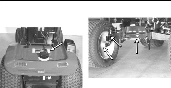
3.One located on the front axle pivot area (1 total) (Figure 4).
|
|
|
|
|
|
|
|
|
Figure 4 |
|
MVC-746 |
4.NOTE: On 2004 models, there is a grease zerk located on the forward/reverse pedal.
Greasing and Lubrication
The machine should be greased every 50 hours or yearly, whichever occurs first. You should grease more frequently when operating conditions are extremely dusty or sandy.
Grease Type: General-purpose grease.
There are 5 grease fittings located in the front axle area:
1.One located on the inside of each wheel hub (2 total).
2.One located on each end of the front axle for the spindles (2 total).
Front Wheel Toe-in
If there is uneven tire wear, lawn scuffing, or hard steering, toe-in may need to be adjusted. The front toe-in measurement should be 1/8” to ¼” (3 to 6mm). This should be checked every 100 hours or once a year, whichever occurs first.
MEASUREMENT:
1.Disengage the PTO, set the parking brake, and turn the ignition key to OFF to stop the engine. Remove the key.
400XT Series Tractor Service Manual |
2 - 1 |
CHASSIS
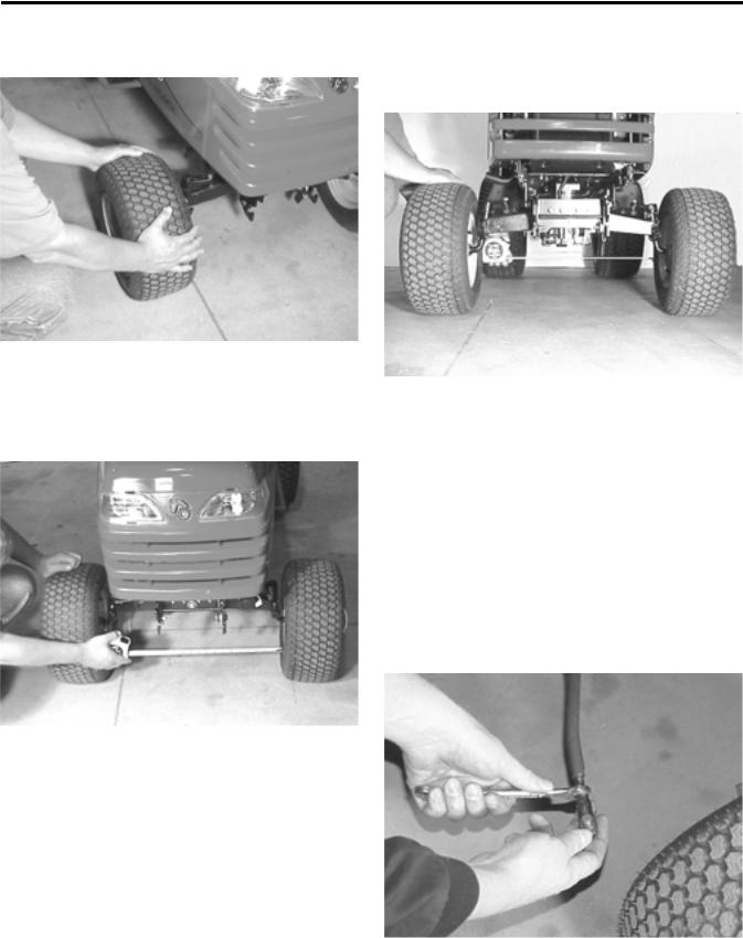
2.Push the front of the tires out to remove normal looseness in the linkage (Figure 5).
|
|
Figure 5 |
MVC-747 |
3.Measure the distance between both the front rims at spindle level, in front and rear of the wheels. You can also measure between the tread mold marks if the tires are new (Figure 6).
|
|
Figure 6 |
MVC-749 |
4.The front measurement should be 1/8” to ¼” (3mm to 6mm) less than the rear measurement (Figure 7). If needed, follow the adjustment procedure.
|
|
Figure 7 |
MVC-752 |
Front Wheel Toe-in Adjustment
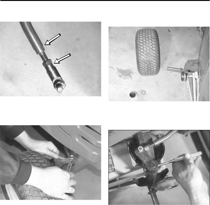
1.Remove the tie rod from one steering arm.
2.Loosen the jam nut securing the ball joint to the steering rod. Rotate the ball joint one turn: clockwise to increase toe-in; counterclockwise to decrease toe-in (Figure 8).
IMPORTANT: If more than one turn is required to meet specifications, alternate between the right and left steering rods to maintain steering wheel alignment.
|
|
Figure 8 |
MVC-095X |
2 - 2 |
400XT Series Tractor Service Manual |
CHASSIS
3.Hold the flats on the ball joint to align with the flats on the tie rod and tighten the jam nut (Figure 9).
3.Remove the outer hub cap, cotter pin, washer, and hub cap washer. Slide the wheel and tire off the spindle (Figure 11).
|
|
Figure 9 |
MVC-098X |
4.Install the ball joint to the steering arm and check the toe-in as described in the measurement section (Figure 10).
|
|
Figure 11 |
MVC-100X |
4.Remove the tie rod from the front spindle arm. With a drift punch and hammer, drive the roll pin out of the front spindle arm (Figure 12).
|
|
Figure 10 |
MVC-099X |
Figure 12 |
MVC-732X |
Front Wheel and Spindle Removal
and Installation
Removal
1.Disengage the PTO. Set the parking brake, and turn the ignition key to OFF to stop the engine. Remove the key.
2.Raise the front axle by putting a jack under the side you are removing the wheel or spindle from.
400XT Series Tractor Service Manual |
2 - 3 |

CHASSIS
5.The spindle can now be removed out the bottom of the front axle assembly (Figure 13).
|
|
Figure 13 |
MVC-102X |
6.Installation – reverse the order of removal.
Front Axle Removal and Installation
1.Jack-up the front of the tractor. Put jack stands under the frame, just behind the front axle assembly (Figure 14).
|
|
Figure 14 |
MVC-756 |
2.Using a drift punch and hammer, drive the roll pin out of the front spindle arms and remove the arms from the spindles (Figure 15). Remove the wheels with steering spindles, from the axle.
|
|
Figure 15 |
MVC-757 |
3.On the front of the axle, in the center, remove the E-ring and washers (Figure 16).
|
|
Figure 16 |
MVC-758 |
2 - 4 |
400XT Series Tractor Service Manual |
CHASSIS
4.On the back side of the axle assembly, remove the bolt securing the axle pin (Figure 17).
|
|
Figure 17 |
mvc-761 |
5.Remove the axle pin; use a drift punch and hammer to tap the axle pin out; if needed. Lower the axle assembly out of the tractor frame (Figure 18).
|
|
Figure 18 |
MVC-763 |
6.Installation - reverse the order of removal.
Steering Gear
Description
The steering gear assembly is made up of a vertically mounted steering shaft and a horizontal sector gear. The sector gear is adjustable so that excessive backlash play in steering gears can be removed (Figure 19).
|
|
Figure 19 |
6-8 |
Steering Backlash Adjustment
Use the following procedure if there is excessive steering backlash.
1.Remove battery and battery tray from the tractor.
400XT Series Tractor Service Manual |
2 - 5 |
Loading...