


Toro 13AX61RG848, 37770, 37771, 37772, 37775 Service Manual
...Consumer Products
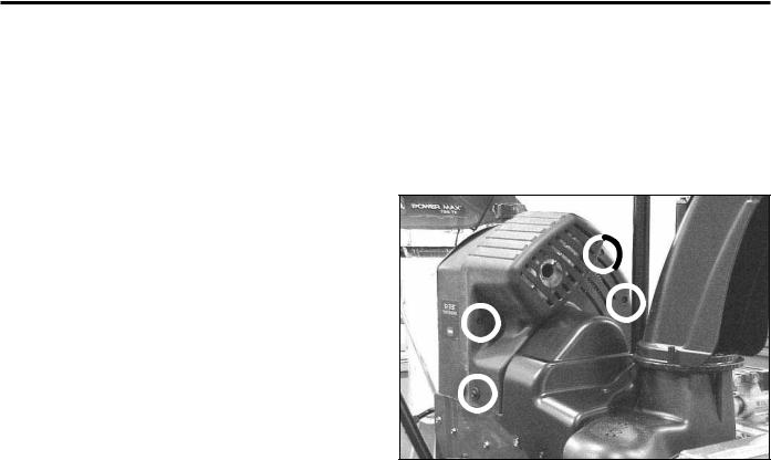
Power Max™
Snowthrower
Service Manual

ABOUT THIS MANUAL
This service manual was written expressly for Toro service technicians. The Toro Company has made every effort to make the information in this manual complete and correct.
Basic shop safety knowledge and mechanical/electrical skills are assumed. The Table of Contents lists the systems and the related topics covered in this manual.
For information specifi c to the engines used on this unit, refer to the engine chapter of this book.
Power Max model years 2004 - 2005 are covered in this manual. The manual may also be specifi ed for use on later model products.
We are hopeful that you will fi nd this manual a valuable addition to your service shop. If you have questions or comments regarding this manual, please contact us at the following address:
The Toro Company
Consumer Service Department
8111 Lyndale Avenue South
Bloomington, MN 55420-1196
The Toro Company reserves the right to change product specifi cations or this manual without notice.
Copyright© All Rights Reserved
©2005 The Toro Company

TABLE OF CONTENTS
SAFETY INFORMATION |
|
|
Safety Information . . . . . . . . . . . . . . . . . . . . . . . . . |
1 |
- 1 |
SPECIFICATIONS |
|
|
Specifi cations . . . . . . . . . . . . . . . . . . . . . . . . . . . |
2 |
- 1 |
Torque Specifi cations . . . . . . . . . . . . . . . . . . . . . . . |
2 |
- 3 |
ENGINE |
|
|
Service Information . . . . . . . . . . . . . . . . . . . . . . . . |
3 |
- 1 |
Servicing the R tek Engine . . . . . . . . . . . . . . . . . . . . . |
3 |
- 1 |
Primer Button . . . . . . . . . . . . . . . . . . . . . . . . . . . |
3 |
- 2 |
Ignition Switch . . . . . . . . . . . . . . . . . . . . . . . . . . . |
3 |
- 2 |
Fuel Tank, Fuel Line, Fuel Filter . . . . . . . . . . . . . . . . . . |
3 |
- 3 |
Prime Line Routing . . . . . . . . . . . . . . . . . . . . . . . . |
3 |
- 3 |
Engine Shroud Assembly . . . . . . . . . . . . . . . . . . . . . |
3 |
- 3 |
CONTROLS |
|
|
Quick Stick . . . . . . . . . . . . . . . . . . . . . . . . . . . . . |
4 |
- 1 |
Operation . . . . . . . . . . . . . . . . . . . . . . . . . |
4 |
- 1 |
Removal . . . . . . . . . . . . . . . . . . . . . . . . . |
4 |
- 1 |
Disassembly . . . . . . . . . . . . . . . . . . . . . . . |
4 |
- 3 |
Reassembly . . . . . . . . . . . . . . . . . . . . . . . |
4 |
- 4 |
Installation . . . . . . . . . . . . . . . . . . . . . . . . |
4 |
- 5 |
Control Interlock . . . . . . . . . . . . . . . . . . . . . . . . . . |
4 |
- 5 |
Control Operation, Replacement & Adjustment . . . . . . . . . . |
4 |
- 7 |
Defl ector Cable |
4 |
- 7 |
Defl ector Cable Adjustment |
4 |
- 8 |
Shift Lever . . . . . . . . . . . . . . . . . . . . . . . . . . . . . |
4 |
- 8 |
Shift Rod Adjustment . . . . . . . . . . . . . . . . . . . |
4 |
- 8 |
Auger Control . . . . . . . . . . . . . . . . . . . . . . . |
4 |
- 9 |
Auger Cable Adjustment . . . . . . . . . . . . . . . . . |
4 |
- 9 |
Auger Brake Adjustment . . . . . . . . . . . . . . . . . |
4 |
- 10 |
Traction Control . . . . . . . . . . . . . . . . . . . . . . |
4 |
- 10 |
Traction Cable Adjustment . . . . . . . . . . . . . . . . |
4 |
- 11 |
Replace & Adjust Wheel Clutch Cables . . . . . . . . . . . . . . |
4 |
- 11 |
ii |
Power Max Service Manual |

TABLE OF CONTENTS
BELT REPLACEMENT |
|
|
Auger Belt . . . . . . . . . . . . . . . . . . . . . . . . . . . . . |
5 |
- 1 |
Traction Belt . . . . . . . . . . . . . . . . . . . . . . . . . . . . |
5 |
- 2 |
AUGER HOUSING |
|
|
Auger Housing Components . . . . . . . . . . . . . . . . . . . . |
6 - 1 |
|
Skids . . . . . . . . . . . . . . . . . . . . . . . . . . . . . . . . |
6 |
- 1 |
Scraper . . . . . . . . . . . . . . . . . . . . . . . . . . . . . . |
6 |
- 1 |
Fixed Scraper . . . . . . . . . . . . . . . . . . . . . . . |
6 |
- 1 |
Scraper Replacement . . . . . . . . . . . . . . . . . . |
6 - 1 |
|
Adjusting the Skids and Scraper - Fixed . . . . . . . . . |
6 - 2 |
|
Pivoting Scraper . . . . . . . . . . . . . . . . . . . . . |
6 |
- 2 |
Scraper Replacement & Adjustment . . . . . . . . . . . |
6 - 2 |
|
Adjusting the Skids and Scraper - Pivoting . . . . . . . . |
6 - 3 |
|
AUGER GEARBOX |
|
|
Auger Gearbox Removal Primary Method . . . . . . . . . . . . . |
7 - 1 |
|
Separating the Auger & Traction Assemblies |
|
|
Secondary Method . . . . . . . . . . . . . . . . . . . . |
7 - 4 |
|
Gearbox Installation . . . . . . . . . . . . . . . . . . . . . . . . |
7 |
- 5 |
Auger Gearbox Repair . . . . . . . . . . . . . . . . . . . . . . . |
7 - 6 |
|
Lubrication . . . . . . . . . . . . . . . . . . . . . . . . |
7 |
- 6 |
Gearbox Disassembly & Repair . . . . . . . . . . . . . |
7 - 6 |
|
Failure Analysis . . . . . . . . . . . . . . . . . . . . . . |
7 |
- 7 |
Gearbox Assembly . . . . . . . . . . . . . . . . . . . . |
7 - 8 |
|
NON-WHEEL CLUTCH TRACTION DRIVE SYSTEM |
|
|
General Description . . . . . . . . . . . . . . . . . . . . . . . . |
8 |
- 1 |
Disassembly . . . . . . . . . . . . . . . . . . . . . . . . . . . . |
8 |
- 1 |
Reassembly . . . . . . . . . . . . . . . . . . . . . . . . . . . . |
8 |
- 6 |
WHEEL CLUTCH TRACTION DRIVE SYSTEM |
|
|
General Description . . . . . . . . . . . . . . . . . . . . . . . . |
9 |
- 1 |
Disassembly . . . . . . . . . . . . . . . . . . . . . . . . . . . . |
9 |
- 1 |
Drive System Reassembly . . . . . . . . . . . . . . . . . . . . . |
9 - 9 |
|
Power Max Service Manual |
iii |

TABLE OF CONTENTS
WHEEL CLUTCH TRACTION DRIVE SYSTEM (cont.) |
|
|
Wheel Clutch Disassembly . . . . . . . . . . . . . . . . . . . . |
9 - 17 |
|
Wheel Clutch Reassembly . . . . . . . . . . . . . . . . . . . . . |
9 - 20 |
|
DISCHARGE CHUTE |
|
|
Chute & Auger Cover Removal . . . . . . . . . . . . . . . . . . |
10 - 1 |
|
Chute Gears . . . . . . . . . . . . . . . . . . . . . . . . . . . . |
10 |
- 4 |
Operation . . . . . . . . . . . . . . . . . . . . . . . . . |
10 |
- 4 |
Disassembly . . . . . . . . . . . . . . . . . . . . . . . |
10 |
- 4 |
Assembly . . . . . . . . . . . . . . . . . . . . . . . . . |
10 |
- 6 |
ELECTRICAL |
|
|
Electric Start System . . . . . . . . . . . . . . . . . . . . . . . . |
11 - 1 |
|
Lighting . . . . . . . . . . . . . . . . . . . . . . . . . . . . . . |
11 - 1 |
|
Ignition Switch . . . . . . . . . . . . . . . . . . . . . . . . . . . |
11 - 1 |
|
WHEELS and TIRES |
|
|
Wheels . . . . . . . . . . . . . . . . . . . . . . . . . . . . . . . |
12 |
- 1 |
Tires . . . . . . . . . . . . . . . . . . . . . . . . . . . . . . . . |
12 |
- 1 |
iv |
Power Max Service Manual |

SAFETY INFORMATION
General Information
This symbol means WARNING or PERSONAL SAFETY INSTRUCTION - read the instruction because it has to do with your safety. Failure to comply with the instruction may result in personal injury or even death.
This manual is intended as a service and repair manual only. The safety instructions provided herein are for troubleshooting, service, and repair of the Power Max™ snowthrower. The Power Max™ snowthrower operator’s
manual contains safety information and operating tips for safe operating practices. Operator’s manuals are available through your parts source or:
The Toro Company
Publications Department
8111 Lyndale Avenue South
Bloomington, MN 55420
Think Safety First
Avoid unexpected starting of engine...
Always turn off the engine and disconnect the spark plug wire(s) before cleaning, adjusting, or repair.
Avoid lacerations and amputations...
Stay clear of all moving parts whenever the engine is running. Treat all normally moving parts as if they were moving whenever the engine is running or has the potential to start.
Avoid burns...
Do not touch the engine, muffler, or other components which may increase in temperature during operation, while the unit is running or shortly after it has been running.
Avoid fires and explosions...
Avoid spilling fuel and never smoke while working with any type of fuel or lubricant. Wipe up any spilled fuel or oil immediately. Never remove the fuel cap or add fuel when the engine is running. Always use approved, labeled containers for storing or transporting fuel and lubricants.
Avoid asphyxiation...
Never operate an engine in a confined area without proper ventilation.
Avoid injury due to inferior parts...
Use only original equipment parts to ensure that important safety criteria are met.
Avoid injury to bystanders...
Always clear the area of bystanders before starting or testing powered equipment.
Avoid injury due to projectiles...
Always clear the area of sticks, rocks, or any other debris that could be picked up and thrown by the powered equipment.
Avoid modifications...
Never alter or modify any part unless it is a factory approved procedure.
Power Max Service Manual |
1-1 |
THIS PAGE INTENTIONALLY LEFT BLANK
1-2 |
Power Max Service Manual |
|
|
|
|
|
SPECIFICATIONS |
||
|
|
|
|
|
|
|
|
|
Engine RPM |
|
|
|
|
|
|
|
2-cycle |
|
|
4,000 +250 -250 RPM |
|
|
|
|
4-cycle |
|
|
3,300 +150 -150 RPM |
|
|
|
|
|
|
|
|
|
|
|
|
Auger |
|
|
|
|
|
|
|
26” |
|
|
26” (66cm) Wide & 21.5” (54.6cm) High |
|
|
|
|
|
|
|
|
|
|
|
|
28” |
|
|
28” (71cm) Wide & 21.5” (54.6cm) High |
|
|
|
|
|
|
|
|
|
|
|
|
Auger Speed |
|
123 RPM @ engine RPM listed above |
|
|
||
|
|
|
|
|
|
|
|
|
Impeller |
|
|
12” Dia. (30.5cm) |
|
|
|
|
|
|
|
|
|
|
|
|
Impeller Speed |
|
1228 RPM @ engine RPM listed above |
|
|
||
|
|
|
|
|
|
|
|
|
Chute Rotation |
|
200 degrees |
|
|
||
|
|
|
|
|
|
|
|
|
Defl ector tilt angle |
|
70 degrees |
|
|
||
|
|
|
|
|
|
|
|
|
Tires Semi pneumatic |
|
15x500x6 |
|
|
||
|
|
|
|
|
|
|
|
|
Pressure |
|
|
17-20 psi ( 116-137kPa) |
|
|
|
|
|
|
|
|
|
|
|
|
Ground speeds |
|
|
|
|
|
|
|
Forward |
|
|
0.7, 1.1, 1.5, 1.9, 2.3, 2.7 mph |
|
|
|
|
|
|
|
(1.1, 1.8, 2.4, 3.0, 3.7, 4.3 kph) |
|
|
|
|
Reverse |
|
|
1.0 & 1.6 mph |
|
|
|
|
|
|
|
(1.6 & 2.5 kph) |
|
|
|
|
|
|
|
|
|
|
|
|
Height |
|
|
44.5” (113cm) Approx. |
|
|
|
|
|
|
|
|
|
|
|
|
Overall Width |
|
27.5” (69.8cm) and 29.5” (74.9cm) |
|
|
||
|
|
|
|
|
|
|
|
|
Length |
|
|
62” (157cm) |
|
|
|
|
|
|
|
|
|
|
|
|
Weight |
|
|
724= 210 lbs (462kg) 826= 238 lbs (526kg) |
|
|
|
|
|
|
|
828 & 1028= 245 lbs (539kg) 1128= 253 lbs (556kg) |
|
|
|
|
|
|
|
|
|
|
|
|
Fuel Capacity |
|
|
|
|
|
|
|
2 cycle engine |
|
1.46 US qts (1.38l) |
|
|
||
|
|
|
|
|
|
|
|
|
4 cycle engine |
|
4 US qts (3.8l) |
|
|
||
|
|
|
|
|
|
|
|
|
|
|
|
|
|
|
|
|
Fuel/oil |
|
|
|
|
|
|
|
2-cycle |
Fuel |
|
Unleaded regular grade gasoline mixed at a ratio of 50:1 |
|
||
|
|
|
|
|
2.6 oz. (80ml) oil / 1 US gallon (3.8l) gasoline. |
|
|
|
|
|
|
|
|
||
|
2-cycle |
Required oil |
|
Toro 2 cycle oil or any 2-cycle oil that is NMMA TCW3 |
|
||
|
|
|
|
|
(ISO E GD) certifi ed as an acceptable substitute. |
|
|
|
|
|
|
|
|
||
|
4-cycle |
Fuel |
|
Unleaded regular grade gasoline (do not mix with oil). |
|
||
|
|
|
|
|
|
||
|
4-cycle |
Oil |
|
automotive detergent oil with a service classifi cation of |
|
||
|
|
|
|
|
SH or higher Maximum capacity 26 oz. (770ml) |
|
|
|
|
|
|
||||
|
The recommended weight varies with the outside temperature |
||||||
|
|
|
|||||
|
For Temps Above 320 F (00 C) |
use SAE 30W |
|
||||
|
For Temps Between 00 F and |
use SAE 5W30 or SAE 10W |
|
||||
|
320 F ( -180 C to 00 C) |
|
|
|
|
||
|
For Temps Below 00 F (-180 C) |
use SAE 0W30 |
|
||||
|
Auger Gearbox lubricant* |
|
SAE 90 gear oil with a rating of GL5 or higher |
|
|||
|
|
|
|
|
|
|
|
*A multi weight may be used such as 85-120 as long as it meets the GL rating. Place the unit on level ground and fi ll to the fi ll/check plug. Maximum capacity 4 oz (118ml).
Power Max Service Manual |
2-1 |

SPECIFICATIONS
The following parts should be lightly coated with an anti-seize compound when assembling after making repairs.
1.The impeller shaft, before installing the impeller pulley.
2.The engine crankshaft before installing the engine pulley.
3.The full length of the auger shaft before installing the augers.
4.The outer 5” (12.7cm) of the axle before installing the wheels.
Accessories
•Drift Breaker
•Tire Chains
•Snow Cab
•Weight Kit (Required with Cab)
2-2 |
Power Max Service Manual |
SPECIFICATIONS
Torque Specifications |
Fastener Identification |
Recommended fastener torque values are listed in the following tables. For critical applications, as determined by Toro, either the recommended torque or a torque that is unique to the application is clearly identified and specified in the service manual.
These torque specifications for the installation and tightening of fasteners shall apply to all fasteners which do not have a specific requirement identified in the service manual. The following factors shall be considered when applying torque: cleanliness of the fastener, use of a thread sealant (Loctite), degree of lubrication on the fastener, presence of a prevailing torque feature, hardness of the surface underneath of the fastener’s head, or similar condition which affects the installation.
As noted in the following tables, torque values should be reduced by 25% for lubricated fasteners to achieve the similar stress as a dry fastener. Torque values may also have to be reduced when the fastener is threaded into aluminum or brass. The specific torque value should be determined based on the aluminum or brass material strength, fastener size, length of thread engagement, etc.
The standard method of verifying torque shall be performed by marking a line on the fastener (head or nut) and mating part, then back off fastener 1/4 of a turn. Measure the torque required to tighten the fastener until the lines match up.
|
|
|
|
Figure 1 |
|
|
||
Inch Series Bolts and Screws |
||
|
|
|
(A) Grade 1 |
|
(C) Grade 8 |
(B) Grade 5 |
|
|
|
|
|
|
|
|
|
|
|
Figure 2
Metric Bolts and Screws
(A) Class 8.8 |
(B) Class 10.9 |
|
|
Power Max Service Manual |
2-3 |

SPECIFICATIONS
Standard Torque for Dry, Zinc Plated, and Steel Fasteners (Inch Series)
|
Grade 1, 5, & |
SAE Grade 1 Bolts, Screws, |
SAE Grade 5 Bolts, Screws, |
SAE Grade 8 Bolts, Screws, |
|||||||||||||
Thread Size |
8 with Thin |
Studs, & Sems with Regular |
Studs, & Sems with Regular |
Studs, & Sems with Regular |
|||||||||||||
Height Nuts |
Height Nuts (SAE J995 |
Height Nuts (SAE J995 |
Height Nuts (SAE J995 |
||||||||||||||
|
|||||||||||||||||
|
|
|
Grade 2 or Stronger Nuts) |
Grade 2 or Stronger Nuts) |
Grade 2 or Stronger Nuts) |
||||||||||||
|
In-lb |
|
In-lb |
|
N-cm |
|
In-lb |
|
N-cm |
|
|
In-lb |
|
N-cm |
|
|
|
|
|
|
|
|
|
|
|
|
|
|
|
|
|
|
|
|
|
# 6 - 32 UNC |
10 |
± 2 |
13 |
± 2 |
147 |
± 23 |
15 |
± 2 |
170 |
± |
20 |
23 |
± 2 |
260 |
± |
20 |
|
# 6 - 40 UNF |
17 |
± 2 |
190 |
± |
20 |
25 |
± 2 |
280 |
± |
20 |
|||||||
|
|
|
|
|
|
||||||||||||
# 8 - 32 UNC |
13 |
± 2 |
25 |
± 5 |
282 |
± 30 |
29 |
± 3 |
330 |
± |
30 |
41 |
± 4 |
460 |
± |
45 |
|
# 8 - 36 UNF |
31 |
± 3 |
350 ± 30 |
43 |
± 4 |
31 ± 3 |
|||||||||||
|
|
|
|
|
|
||||||||||||
# 10 - 24 UNC |
18 |
± 2 |
30 |
± 5 |
339 |
± 56 |
42 |
± 4 |
475 |
± 45 |
60 |
± 6 |
674 |
± 70 |
|||
#10 - 32 UNF |
48 |
± 4 |
540 |
± 45 |
68 |
± 6 |
765 |
± 70 |
|||||||||
|
|
|
|
|
|
||||||||||||
1/4 - 20 UNC |
48 |
± 7 |
53 |
± 7 |
599 |
± 79 |
100 |
± 10 |
1125 ± 100 |
140 |
± 15 |
1580 |
± 170 |
||||
1/4 - 28 UNF |
53 |
± 7 |
65 ± 10 |
734 ± 113 |
115 ± 10 |
1300 |
± 100 |
160 |
± 15 |
1800 |
± 170 |
||||||
5/16 - 18 UNC |
115 ± 15 |
105 |
± 17 |
1186 ± 169 |
200 |
± 25 |
2250 |
± 280 |
300 |
± 30 |
3390 |
± 340 |
|||||
5/16 - 24 UNF |
138 |
± 17 |
128 |
± 17 |
1446 |
± 192 |
225 |
± 25 |
2540 |
± 280 |
325 |
± 30 |
3670 |
± 340 |
|||
|
ft-lb |
ft-lb |
N-m |
ft-lb |
N-m |
ft-lb |
N-m |
||||||||||
3/8 - 16 UNC |
16 |
± 2 |
16 |
± 2 |
22 |
± 3 |
30 |
± 3 |
41 |
± 4 |
43 |
± 4 |
58 |
± 5 |
|||
3/8 - 24 UNF |
17 |
± 2 |
18 |
± 2 |
24 |
± 3 |
35 |
± 3 |
47 |
± 4 |
50 |
± 4 |
68 |
± 5 |
|||
7/16 - 14 UNC |
27 |
± 3 |
27 |
± 3 |
37 |
± 4 |
50 |
± 5 |
68 |
± 7 |
70 |
± 7 |
68 |
± 9 |
|||
7/16 - 20 UNF |
29 |
± 3 |
29 |
± 3 |
39 |
± 4 |
55 |
± 5 |
75 |
± 7 |
77 |
± 7 |
104 ± 9 |
||||
1/2 - 13 UNC |
30 |
± 3 |
48 |
± 7 |
65 |
± 9 |
75 |
± 8 |
102 ± 11 |
105 |
± 10 |
142 |
± 14 |
||||
1/2 - 20 UNF |
32 |
± 3 |
53 |
± 7 |
72 |
± 9 |
85 |
± 8 |
115 |
± 11 |
120 |
± 10 |
163 |
± 14 |
|||
5/8 - 11 UNC |
65 ± 10 |
88 ± 12 |
119 ± 16 |
150 |
± 15 |
203 |
± 20 |
210 |
± 20 |
285 |
± 27 |
||||||
5/8 - 18 UNF |
75 ± 10 |
95 ± 15 |
129 |
± 20 |
170 |
± 15 |
230 |
± 20 |
240 |
± 20 |
325 |
± 27 |
|||||
3/4 - 10 UNC |
93 ± 12 |
140 |
± 20 |
190 |
± 27 |
265 |
± 25 |
359 |
± 34 |
374 |
± 35 |
508 |
± 47 |
||||
3/4 - 16 UNF |
115 ± 15 |
165 |
± 25 |
224 |
± 34 |
300 |
± 25 |
407 |
± 34 |
420 |
± 35 |
569 |
± 47 |
||||
7/8 - 9 UNC |
140 |
± 20 |
225 |
± 25 |
305 |
± 34 |
430 |
± 45 |
583 |
± 61 |
600 |
± 60 |
813 |
± 81 |
|||
7/8 - 14 UNF |
155 |
± 25 |
260 |
± 30 |
353 |
± 41 |
475 |
± 45 |
644 |
± 61 |
660 |
± 60 |
895 |
± 81 |
|||
|
|
|
|
|
|
|
|
|
|
|
|
|
|
|
|
|
|
Note: Reduce torque values listed in the table above by 25% for lubricated fasteners. Lubricated fasteners are defined as threads coated with a lubricant such as oil, graphite, or thread sealant such as Loctite.
Note: Torque values may have to be reduced when installing fasteners into threaded aluminum or brass. The specific torque value should be determined based on the fastener size, the aluminum or base material strength, length of thread engagement, etc.
Note: The nominal torque values listed above for Grade 5 and 8 fasteners are based on 75% of the minimum proof load specified in SAE J429. The tolerance is approximately ± 10% of the nominal torque value. Thin height nuts include jam nuts.
2-4 |
Power Max Service Manual |

SPECIFICATIONS
Standard Torque for Dry, Zinc, and Steel Fasteners (Metric Fasteners)
|
Class 8.8 Bolts, Screws, and Studs with |
Class 10.9 Bolts, Screws, and Studs with |
|||||||
Thread Size |
|
Regular Height Nuts |
|
Regular Height Nuts ( |
|||||
|
|
(Class 8 or Strong Nuts) |
|
Class 10 or Strong Nuts) |
|||||
M5 X 0.8 |
57 ± 5 in-lb |
640 |
± 60 N-cm |
78 ± 7 in-lb |
885 ± 80 N-cm |
||||
M6 X 1.0 |
96 ± 9 in-lb |
1018 |
± 100 N-cm |
133 ± 13 in-lb |
1500 ± 150 N-cm |
||||
M8 X 1.25 |
19 |
± 2 ft-lb |
26 |
± 3 N-m |
27 |
± 2 ft-lb |
36 |
± 3 N-m |
|
M10 X 1.5 |
38 |
± 4 ft-lb |
52 |
± 5 N-m |
53 |
± 5 ft-lb |
72 |
± 7 N-m |
|
M12 X 1.75 |
66 |
± 7 ft-lb |
90 |
± 10 N-m |
92 |
± 9 ft-lb |
125 |
± 12 N-m |
|
M16 X 2.0 |
166 |
± 15 ft-lb |
225 |
± 20 N-m |
229 |
± 22 ft-lb |
310 |
± 30 N-m |
|
M20 X 2.5 |
325 |
± 33 ft-lb |
440 |
± 45 N-m |
450 |
± 37 ft-lb |
610 |
± 50 N-m |
|
|
|
|
|
|
|
|
|
|
|
Note: Reduce torque values listed in the table above by 25% for lubricated fasteners. Lubricated fasteners are defined as threads coated with a lubricant such as oil, graphite, or thread sealant such as Loctite.
Note: Torque values may have to be reduced when installing fasteners into threaded aluminum or brass. The specific torque value should be determined based on the fastener size, the aluminum or base material strength, length of thread engagement, etc.
Note: The nominal torque values listed above are based on 75% of the minimum proof load specified in SAE J1199. The tolerance is approximately ± 10% of the nominal torque value. Thin height nuts include jam nuts.
Power Max Service Manual |
2-5 |

SPECIFICATIONS
Other Torque Specifications
SAE Grade 8 Steel Set Screws
|
Recommended Torque |
||
Thread Size |
|
|
|
Square Head |
Hex Socket |
||
|
|||
|
|
|
|
1/4 - 20 UNC |
140 ± 20 in-lb |
73 ± 12 in-lb |
|
|
|
|
|
5/16 - 18 UNC |
215 ± 35 in-lb |
145 ± 20 in-lb |
|
|
|
|
|
3/8 - 16 UNC |
35 ± 10 ft-lb |
18 ± 3 ft-lb |
|
|
|
|
|
1/2 - 13 UNC |
75 ± 15 ft-lb |
50 ± 10 ft-lb |
|
|
|
|
|
Wheel Bolts and Lug Nuts
Thread Size |
Recommended Torque** |
||
|
|
|
|
7/16 - 20 UNF |
65 ± 10 ft-lb |
88 ± 14 N-m |
|
Grade 5 |
|||
|
|
||
|
|
|
|
1/2 - 20 UNF |
80 ± 10 ft-lb |
108 ± 14 N-m |
|
Grade 5 |
|||
|
|
||
|
|
|
|
M12 X 1.25 |
80 ± 10 ft-lb |
108 ± 14 N-m |
|
Class 8.8 |
|||
|
|
||
|
|
|
|
M12 X 1.5 |
80 ± 10 ft-lb |
108 ± 14 N-m |
|
Class 8.8 |
|||
|
|
||
|
|
|
|
** For steel wheels and non-lubricated fasteners.
Thread Cutting Screws
(Zinc Plated Steel)
Type 1, Type 23, or Type F
Thread Size |
Baseline Torque* |
|
|
|
|
No. 6 - 32 UNC |
20 |
± 5 in-lb |
|
|
|
No. 8 - 32 UNC |
30 |
± 5 in-lb |
|
|
|
No.10 - 24 UNC |
38 |
± 7 in-lb |
|
|
|
1/4 - 20 UNC |
85 ± 15 in-lb |
|
|
|
|
5/16 - 18 UNC |
110 |
± 20 in-lb |
|
|
|
3/8 - 16 UNC |
200 ± 100 in-lb |
|
|
|
|
Conversion Factors
in-lb X 11.2985 - N-cm
ft-lb X 1.3558 = N-m
Thread Cutting Screws
(Zinc Plated Steel)
Thread |
Threads per Inch |
|
||
|
|
Baseline Torque* |
||
Size |
Type A |
Type B |
||
|
||||
|
|
|||
|
|
|
|
|
No. 6 |
18 |
20 |
20 ± 5 in-lb |
|
|
|
|
|
|
No. 8 |
15 |
18 |
30 ± 5 in-lb |
|
|
|
|
|
|
No. 10 |
12 |
16 |
38 ± 7 in-lb |
|
|
|
|
|
|
No. 12 |
11 |
14 |
85 ± 15 in-lb |
|
|
|
|
|
|
* Hole size, material strength, material thickness and finish must be considered when determining specific torque values. All torque values are based on nonlubricated fasteners.
N-cm X - 0.08851 = in-lb
N-cm X 0.73776 - ft-lb
2-6 |
Power Max Service Manual |

SPECIFICATIONS
Equivalents and Conversions
Decimal and Millimeter Equivalents
Fractions |
Decimals |
mm |
Fractions |
|
Decimals |
mm |
|
|
|
|
|
|
|
|
|
|
|
|
|
|
1/64 |
0.015625 |
0.397 |
|
33/64 |
0.515625 |
13.097 |
|
|
|
|
|
|
|
1/32 |
0.03125 |
0.794 |
16/32 |
|
0.53125 |
13.484 |
|
|
|
|
|
|
|
3/64 |
0.046875 |
1.191 |
|
35/64 |
0.546875 |
13.891 |
|
|
|
|
|
|
|
1/16 |
0.0625 |
1.588 |
9/16 |
|
0.5625 |
14.288 |
|
|
|
|
|
|
|
5/64 |
0.078125 |
1.984 |
|
37/64 |
0.578125 |
14.684 |
|
|
|
|
|
|
|
3/32 |
0.9375 |
2.381 |
19/32 |
|
0.59375 |
15.081 |
|
|
|
|
|
|
|
1/8 |
0.1250 |
3.175 |
5/8 |
|
0.6250 |
15.875 |
|
|
|
|
|
|
|
9/64 |
0.140625 |
3.572 |
|
41/64 |
0.640625 |
16.272 |
|
|
|
|
|
|
|
5/32 |
0.15625 |
3.969 |
21/32 |
|
0.65625 |
16.669 |
|
|
|
|
|
|
|
11/64 |
0.171875 |
4.366 |
|
43/64 |
0.671875 |
17.066 |
|
|
|
|
|
|
|
3/16 |
0.1875 |
4.762 |
11/16 |
|
0.6875 |
17.462 |
|
|
|
|
|
|
|
13/64 |
0.203125 |
5.159 |
|
45/64 |
0.703125 |
17.859 |
|
|
|
|
|
|
|
7/32 |
0.21875 |
5.556 |
23/32 |
|
0.71875 |
18.256 |
|
|
|
|
|
|
|
15/64 |
0.234375 |
5.953 |
|
47/64 |
0.734375 |
18.653 |
|
|
|
|
|
|
|
1/4 |
0.2500 |
6.350 |
3/4 |
|
0.7500 |
19.050 |
|
|
|
|
|
|
|
17/64 |
0.265625 |
6.747 |
|
49/64 |
0.765625 |
19.447 |
|
|
|
|
|
|
|
9/32 |
0.28125 |
7.144 |
25/32 |
|
0.78125 |
19.844 |
|
|
|
|
|
|
|
19/64 |
0.296875 |
7.541 |
|
51/64 |
0.796875 |
20.241 |
|
|
|
|
|
|
|
5/16 |
0.3125 |
7.541 |
13/16 |
|
0.8125 |
20.638 |
|
|
|
|
|
|
|
21/64 |
0.328125 |
8.334 |
|
53/64 |
0.828125 |
21.034 |
|
|
|
|
|
|
|
11/32 |
0.34375 |
8.731 |
27/32 |
|
0.84375 |
21.431 |
|
|
|
|
|
|
|
23/64 |
0.359375 |
9.128 |
|
55/64 |
0.859375 |
21.828 |
|
|
|
|
|
|
|
3/8 |
0.3750 |
9.525 |
7/8 |
|
0.8750 |
22.225 |
|
|
|
|
|
|
|
25/64 |
0.390625 |
9.922 |
|
57/64 |
0.890625 |
22.622 |
|
|
|
|
|
|
|
13/32 |
0.40625 |
10.319 |
29/32 |
|
0.90625 |
23.019 |
|
|
|
|
|
|
|
27/64 |
0.421875 |
10.716 |
|
59/64 |
0.921875 |
23.416 |
|
|
|
|
|
|
|
7/16 |
0.4375 |
11.112 |
15/16 |
|
0.9375 |
23.812 |
|
|
|
|
|
|
|
29/64 |
0.453125 |
11.509 |
|
61/64 |
0.953125 |
24.209 |
|
|
|
|
|
|
|
15/32 |
0.46875 |
11.906 |
31/32 |
|
0.96875 |
24.606 |
|
|
|
|
|
|
|
31/64 |
0.484375 |
12.303 |
|
63/64 |
0.984375 |
25.003 |
|
|
|
|
|
|
|
1/2 |
0.5000 |
12.700 |
1 |
|
1.000 |
25.400 |
|
|
|
|
|
|
|
1 mm = 0.03937 in. |
|
|
0.001 in. = 0.0254 mm |
|
||
|
|
|
|
|
|
|
Power Max Service Manual |
2-7 |

SPECIFICATIONS
U.S. to Metric Conversions
|
To Convert |
Into |
Multiply By |
|
|
|
|
|
|
|
|
|
|
|
|
Miles |
Kilometers |
|
1.609 |
|
Yards |
Meters |
|
0.9144 |
Linear |
Feet |
Meters |
|
0.3048 |
Feet |
Centimeters |
|
30.48 |
|
|
|
|||
Measurement |
Inches |
Meters |
|
|
|
0.0254 |
|||
|
Inches |
Centimeters |
|
|
|
|
2.54 |
||
|
Inches |
Millimeters |
|
|
|
|
25.4 |
||
|
|
|
|
|
|
|
|
|
|
|
Square Miles |
Square Kilometers |
|
2.59 |
Area |
Square Feet |
Square Meters |
|
0.0929 |
Square Inches |
Square Centimeters |
|
6.452 |
|
|
|
|||
|
Acre |
Hectare |
|
0.4047 |
|
|
|
|
|
|
|
|
|
|
|
Cubic Yards |
Cubic Meters |
|
0.7646 |
Volume |
Cubic Feet |
Cubic Meters |
|
0.02832 |
|
Cubic Inches |
Cubic Centimeters |
|
16.39 |
|
|
|
|
|
|
Tons (Short) |
Metric Tons |
|
0.9078 |
Weight |
Pounds |
Kilograms |
|
0.4536 |
|
Ounces |
Grams |
|
28.3495 |
|
|
|
|
|
Pressure |
Pounds/Sq. In. |
Kilopascal |
|
6.895 |
|
|
|
|
|
|
Foot-pounds |
Newton-Meters |
|
1.356 |
Work |
Foot-pounds |
Kilogram-Meters |
|
0.1383 |
|
Inch-pounds |
Kilogram-Centimeters |
|
1.152144 |
|
|
|
|
|
Liquid Volume |
Quarts |
Liters |
|
0.9463 |
Gallons |
Liters |
|
3.785 |
|
|
|
|||
|
|
|
|
|
Liquid Flows |
Gallons/Minute |
Liters/Minute |
|
3.785 |
|
|
|
|
|
Temperature |
Fahrenheit |
Celsius |
1. |
Subtract 32° |
|
|
2. |
Multiply by 5/9 |
|
|
|
|
||
|
|
|
|
|
2-8 |
Power Max Service Manual |
ENGINE
Service Information
The Power Max snowthrowers have both 2-cycle and 4-cycle engines. The process for obtaining parts and service information is different between them.
4-Cycle Engine
All 4 cycle models use a Tecumseh Snow King engine. Service information can be obtained through Tecumseh at the following address.
Tecumseh Products Company
Engine and Transmission Group
Service Division
900 North Street
Grafton, WI 53024
Phone 262-377-2700
2-Cycle Engine
All 2-cycle models use the Toro R tek engine. Service is handled through the Toro system. Detailed engine repair information is available in the “E” Engine Service Manual, Form No. 492-0647.
Servicing the R tek Engine
Use the following process to service the R tek engine.
1.Remove the three screws across the front of the engine shroud and 2 screws on each side where the front and rear shroud meet (Fig. 003).
Fig 003 |
MVC-001X |
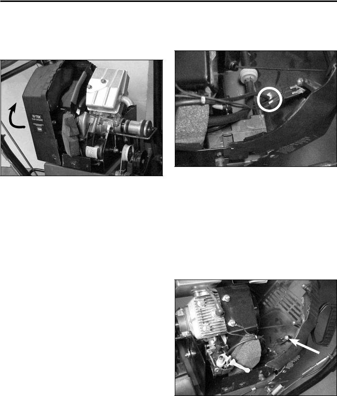
2.Remove 4 screws securing the belt covers; remove the belt covers. (Reassembly will be much easier if the belt covers have been removed.
Power Max Service Manual |
3-1 |
ENGINE
3.Pull the front shroud forward and up to remove. Slide the rear cover to the rear and rotate it clockwise to slip over the electric starter button and extension cord plug located in the left rear corner (Fig. 004).
Fig 004 |
MVC-900XB |
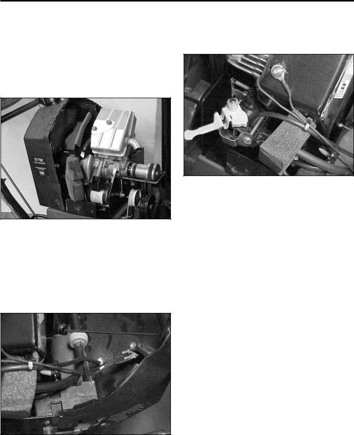
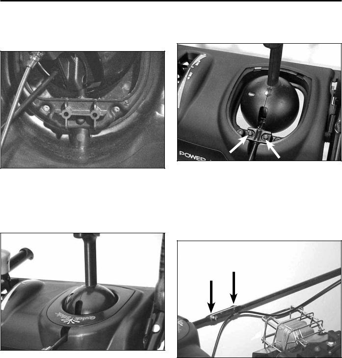
Primer Button
When depressed the primer button pressurizes the carburetor bowl. Fuel is forced up the main tube to the carburetor venturi. This line and button are the atmospheric vent for the carburetor bowl. If the line is kinked or the vent hole in the bulb is plugged, the carburetor may fl ood.
To remove the primer button, pull the primer line off the stem and compress the tabs. The primer will push out to the rear (Fig. 005).
Fig 005 |
MVC-865XA |
Ignition Switch
To remove the ignition switch, pull the wire harness off the switch terminals. The switch is a snap in type. To remove the switch, depress the ears on the switch body (Fig. 006) and push the switch out through the rear of the shroud. Switch troubleshooting is provided in the electrical section.
Fig 006 |
MVC-863XA |
3-2 |
Power Max Service Manual |
ENGINE
Fuel Tank, Fuel Line and Fuel Filter
To remove the fuel tank, unscrew the gas cap, slip the tank out of the shroud and install the cap. If there is fuel in the tank, clamp the line, or drain the tank into a suitable container. Remove the fuel line and fuel fi lter. The tank is held in place by the bracket and shroud surrounding it (Fig. 007).
It should be gathered and secured to the ignition switch wires. It then goes down to the primer fi tting on top of the carburetor (Fig. 009).
Fig 007 |
MVC-000 |
Primer Line Routing
The primer line connects to the back side of the primer then is routed over the fuel line, over the foam block (Fig. 008).
Fig 009 |
MVC-866XA |
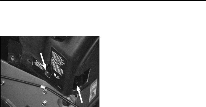
Engine Shroud Assembly
1.Ensure the ignition switch is in place and the wire harness is plugged in, the primer line is attached to the primer and the primer body is secure in its slot, and the fuel tank, fuel line and fi lter are properly installed.
Fig 008 |
MVC-865XA |
Power Max Service Manual |
3-3 |
ENGINE
2.Begin in the left rear corner; slip the shroud over the electric start button and the plug terminal for the extension cord (Fig. 010). Then rotate the shroud clockwise into place.
Fig 010 |
MVC-893XC |
3.While the engine shroud is still loose, install both belt covers. Then install and secure the front and rear engine covers to each other and to the chassis.
3-4 |
Power Max Service Manual |

CONTROLS
QUICK STICK
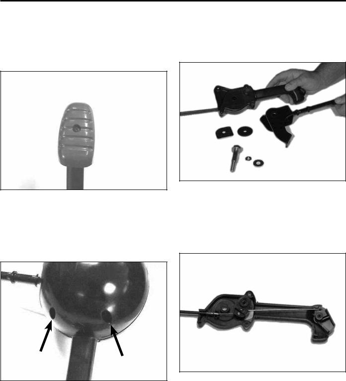
Operation
The Quick Stick is a single lever control for chute side- to-side movement and vertical movement of the defl ector (Fig. 011).
The defl ector up and down motion is unlatched inside the quick stick itself and a cable controls the up and down motion.
Removing the cover just behind the chute allows access to the chute rotation gears and chute latch (Fig. 013). Since these gears are plastic they do not require lubrication. The latch cable adjustment is covered in the control adjustment section.
Fig 011 |
MVC-775X |
When the operator places their hand on the stick the cover is depressed, which draws a cable to unlatch the chute (Fig. 012). Side to side motion rotates the rod and gear and causes the chute to pivot side to side.
Fig 013 |
MVC-772X |
Removal
1.To remove the Quick Stick, unhook the Z bend and disconnect the defl ector cable from the underside of the Quick Stick (Fig. 014).
Fig 012 |
MVC-039F |
Fig 014 |
MVC-870XA |
Power Max Service Manual |
4-1 |
CONTROLS
2.On the underside of the control panel, remove the two screws holding the Quick Stick cover in place (Fig. 015).
4.Remove the two screws that retain the rod support to the control panel (Fig. 017).
Fig 017 |
MVC-819X |
Fig 015 |
MVC-1869X |
3.Lift the front cover and pull forward to release the latch tabs on the rear. Set the cover aside (Fig. 016).
5.Remove the two carriage bolts and nuts on the chute control rod and lift the Quick Stick out of the control panel. Note the location of the cable clamp, as it is necessary for latch cable function (Fig. 018).
Fig 016 |
MVC-902X |
Fig 018 |
MVC-725F |
4-2 |
Power Max Service Manual |
CONTROLS
Disassembly
1.To begin disassembly of the Quick Stick, remove the screw retaining the blue lever cap and remove the cap (Fig. 019).
3.Remove the locknut and fl at washer from the shoulder bolt. Slide the chute control rod off and remove the rubber washer and friction plate (Fig. 021).
Fig 021 |
MVC-832S |
Fig 019 |
MVC-546F |
2.Remove the two screws on the right hand side of the chute control cover (the part that looks like a ball). Remove both halves and set aside (Fig. 020).
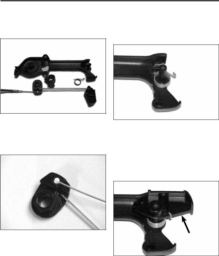
4.Hold the Quick Stick so the three screws holding the handle halves are facing up. Remove the three screws and lift off the top handle half (Fig. 022).
Fig 022 |
MVC-8335X |
Fig 020 |
MVC-547F |
Power Max Service Manual |
4-3 |
CONTROLS
5.Lift the metal latch pawl off the hex on the cable lever. Lift out the latch trigger and spring. Note the orientation of the pawl to the lever for reassembly (Fig. 023).
Reassembly
1.Begin assembly by dropping the latch spring over the boss. The straight end of the spring should be down with the hooked end up (Fig. 025).
Fig 023 |
MVC-837X |
Fig 025 |
MVC-759F |
6.Rotate the cable until the barrel fi tting slides off the cable lever (Fig. 024).
2.Slide the latch trigger over the boss until it is fully seated, making sure that the stop on the trigger lever is above the stop on the quick lever, as shown. While holding the trigger lever in place, rotate the hooked end of the spring until it hooks under the front edge of the trigger lever as shown (Fig. 026).
Fig 024 |
MVC-554F |
A
Fig 026 |
MVC-758F |
A. Latch trigger
4-4 |
Power Max Service Manual |
CONTROLS
3.Reverse the disassembly process for the remainder of the assembly.
Installation
Reverse the removal process for installation.
Note: The cable clamp must be installed on the chute control rod or the cable latch will not function.
Disassembly
1.Disconnect the auger and traction cables from the levers. If this is a wheel clutch model, disconnect the wheel clutch cables (Fig. 028).
CONTROL INTERLOCK
For operator convenience there is an interlock between the auger and traction lever. Once both are engaged you only need to hold the auger lever. This allows a free hand to change chute direction without having to stop. The latch mechanism is located under the dash (Fig. 027).
Fig 028 |
MVC-171X |
2.Remove the Shoulder Screw under the left handgrip (Fig. 029). When it is removed the Lockout Latch, Torsion Spring, Flat Washer, and Locknut will drop out.
Fig 027 |
MVC-872X |
Fig 029 |
MVC-167X |
Power Max Service Manual |
4-5 |
CONTROLS
3.To remove the lockout rod, go to the right hand end. There are 2 roll pins on the right side (Fig. 030) and one in the lockout cam on the left (Fig. 031).
4.Once they are driven out the lockout rod can be moved to the side and removed (Fig. 032). The lockout link can now be removed from the lockout rod.
Fig 030 |
MVC-169X |
Fig 032 |
MVC-172X |
5.Since the auger and traction levers pivot on the lockout rod this is the method required to replace the levers (Fig. 033).
Fig 031 |
MVC-170X |
Fig 033 |
MVC-174X |
Note: Steps 1 and 2 above do not need to be done in that order. In fact you can remove the rod without removing the shoulder bolt and vice versa.
4-6 |
Power Max Service Manual |
CONTROLS
Assembly
Reverse the above process for assembly.
Note the spring on the lockout latch. The end with the slight bend goes behind the lockout latch and the hooked end goes over the small tab. It is easiest to install the latch mechanism then hook the end of the spring with a wire and pull it into place (Fig. 034).
CONTROL OPERATION, REPLACEMENT, AND ADJUSTMENT
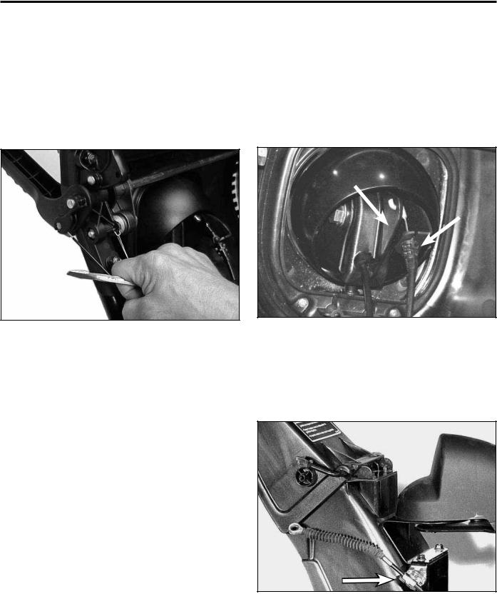
Deflector Cable
1.To remove the defl ector cable, depress the tabs that retain the cable in the bracket, under the control panel. Disconnect the Z bend on the end (Fig. 035).
Fig 034 |
MVC-176X |
Fig 035 |
MVC-870X |
2.Remove the cable clamp and disconnect the cable end from the defl ector. Reverse this process to install a new cable (Fig. 036).
Fig 036 |
MVC-882X |
Power Max Service Manual |
4-7 |
CONTROLS
Deflector Cable Adjustment
Make sure the Quick Stick is in the maximum rear position and centered (Fig. 037); ensure the defl ector is in the full upward position. Draw the slack out of the cable and secure the clamp (Fig. 036).
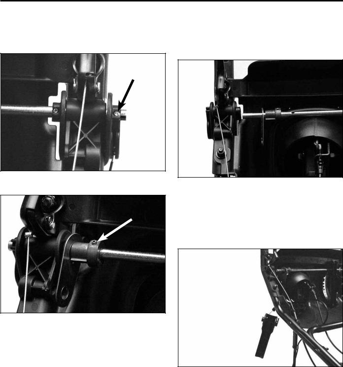
Shift Rod Adjustment
1.The adjustment point is a trunion on the upper end of the shift rod (Fig. 039).
Fig 037 |
MVC-775X |
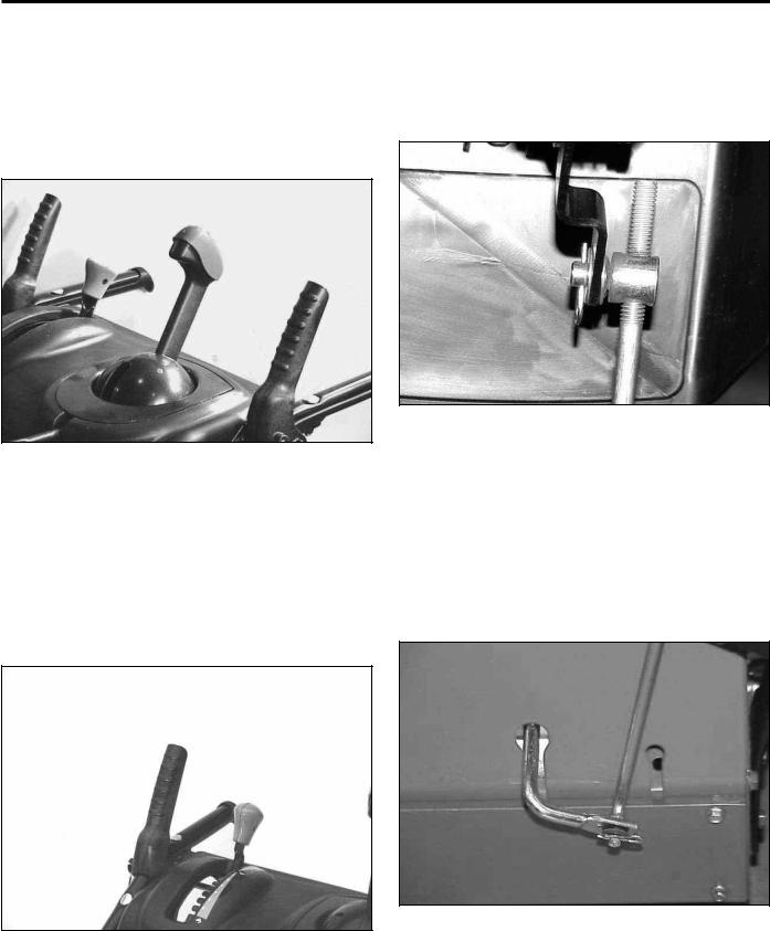
SHIFT LEVER
The shift lever on the control panel is connected to the friction wheel in the traction drive by a shift rod. Moving the shift lever moves the friction wheel to change wheel direction and speed (Fig. 038).
Fig 039 |
MVC-561F |
2.Pull the shift rod and arm upward as far as they will go. With the shift lever in R2, adjust the trunion to take the slack out and resecure (Fig. 040).
Note: Excessive slack in the linkage may cause the drive to be in reverse when shifted into first gear.
Fig 040 |
MVC-560F |
Fig 038 |
MVC-901XA |
4-8 |
Power Max Service Manual |
CONTROLS
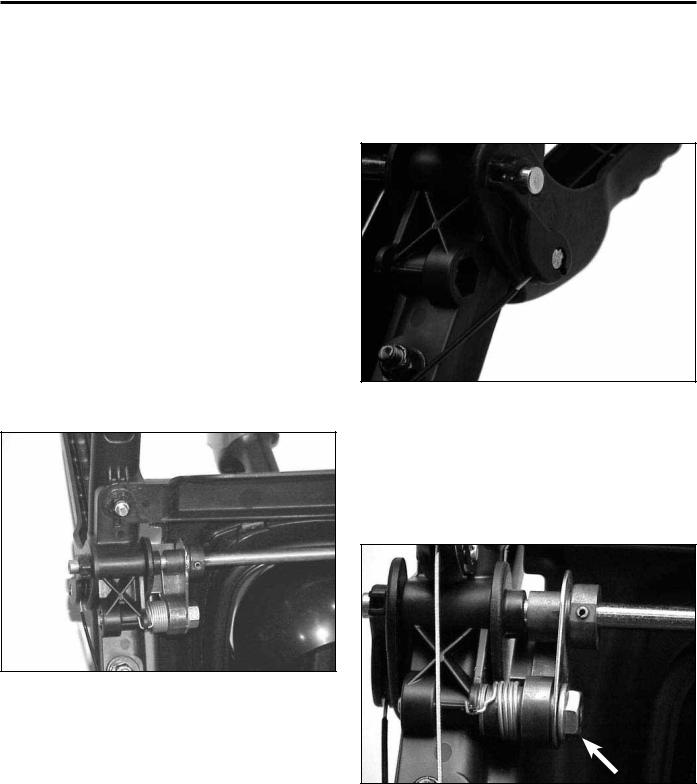
Auger Control
The bail on the right hand handle is the auger control. Squeeze the bail and the cable causes an idler to pivot tensioning the auger belt (Fig. 041).
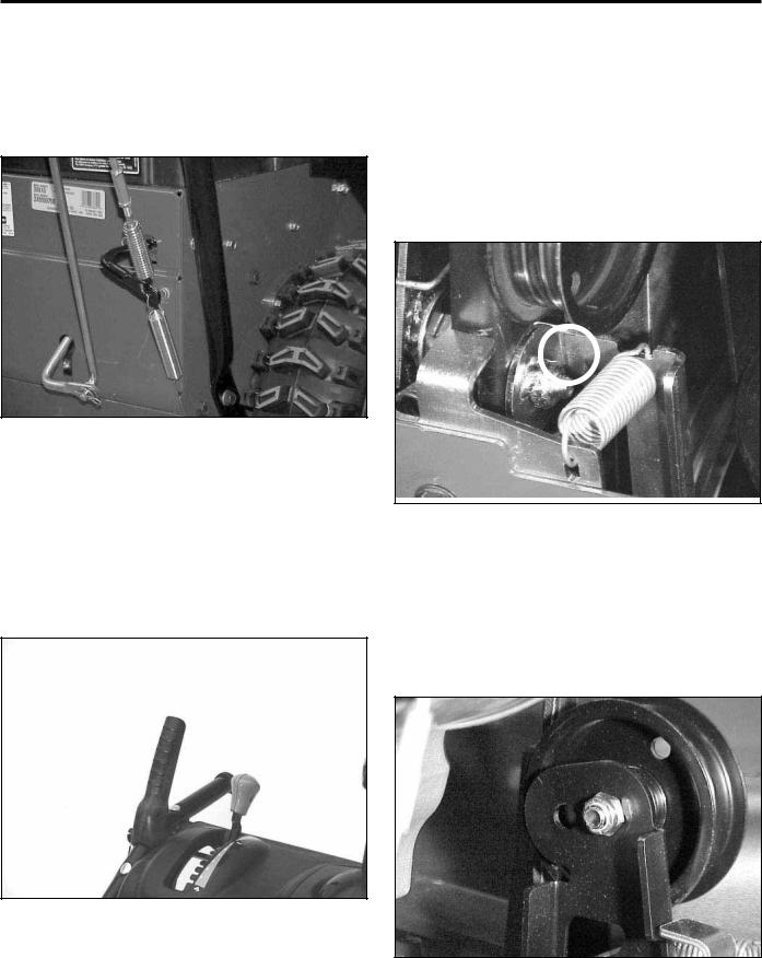
2.Loosen the jam nut. The cable is adjusted using the turnbuckle on the lower end of the auger cable.
Note: When rotating the turnbuckle, hold the cable so it does not twist (Fig. 041).
3.Remove the right side belt cover. Adjust the turnbuckle until there is a 1/16” (1.5mm) gap between the stop and the auger clutch assembly. Secure the jam nut on the turnbuckle (Fig. 043).
Fig 041 |
MVC-816X |
Auger Cable Adjustment
1.The auger cable adjustment should be checked after the fi rst 2 hours of use and annually thereafter. To begin, ensure the auger lever is in the full up position (Fig. 042).
Fig 042 |
MVC-901XA |
Fig 043 |
MVC-876X |
Beginning with 2005 production there are two holes in the idler arm (Fig. 044). The idler pulley is initially installed in the outer hole. If necessary, the idler can be moved to achieve the correct tension. 2004 models have only one hole in the idler.
Fig 044 |
MVC-016X |
Power Max Service Manual |
4-9 |
 Loading...