


Toro 20040, 20486, 20487, 20488, 20786 Service Manual
...TORO GTS 200 OVERHEAD VALVE ENGINE SERVICE MANUAL
Table of Contents – Page 1 of 2
SPECIFICATIONS
GENERAL INFORMATION
OIL
GASOLINE
COOLING SYSTEM
AIR CLEANER – GENERAL
AIR CLEANER SERVICE
TUNE-UP PROCEDURE
OVERHAUL PROCEDURE
CHECK-UP
EQUIPMENT AFFECTING ENGINE OPERATION
IGNITION
CHECK IGNITION SPARK PLUG REMOVE FLYWHEEL
INSPECT FLYWHEEL KEY, KEYWAYS, FLYWHEEL, AND CRANKSHAFT INSTALL FLYWHEEL
SPECIFICATIONS
CARBURETION
CARBURETOR IDENTIFICATION
SERVICE CARBURETOR WALBRO LMS
GOVERNOR CONTROLS, CARBURETOR LINKAGE, AND FLYWHEEL BRAKE REMOTE GOVERNOR CONTROLS
FLYWHEEL BRAKE GOVERNOR ADJUSTMENTS
GOVERNOR AND CARBURETOR LINKAGES
GOVERNOR
GENERAL INFORMATION
GOVERNED RPM LIMITS
MECHANICAL GOVERNOR
COMPRESSION
TEST COMPRESSION
REMOVE CYLINDER HEAD
VALVE SERVICE
ASSEMBLE CYLINDER HEAD
SPECIFICATION TABLES
REWIND STARTER
GENERAL INFORMATION
REMOVE BLOWER HOUSING AND STARTER

TORO GTS 200 OVERHEAD VALVE ENGINE SERVICE MANUAL
Table of Contents – Page 2 of 2
DISASSEMBLE REWIND STARTER
ASSEMBLE REWIND STARTER
ELECTRIC STARTER
GENERAL INFORMATION
TROUBLESHOOTING 12 VOLT STARTING SYSTEM
TEST EQUIPMENT
BATTERY
STARTER
ALTERNATOR
ALTERNATOR SPECIFICATIONS EQUIPMENT TO TEST ALTERNATORS 1/2 AMP ALTERNATOR
LUBRICATION
EXTENDED OIL FILL AND DIPSTICK
BREATHER
REMOVE BREATHER
INSTALL BREATHER VALVE
REMOVE OIL PUMP
INSPECT OIL PUMP
INSTALL OIL PUMP
INSTALL PUMP COVER
INSTALL OIL FILTER ADAPTER
PISTONS, RINGS, AND RODS
PISTON AND CONNECTING ROD
SPECIFICATION TABLES
CRANKSHAFT AND CAMSHAFT
REMOVE CRANKSHAFT AND CAMSHAFT
INSTALL CRANKSHAFT AND CAMSHAFT
SPECIFICATION TABLES
CYLINDER AND BEARINGS
CYLINDER
PLAIN OR DUTM BEARINGS
CRANKCASE SUMP
SPECIFICATION TABLES
MUFFLER
REMOVE EXHAUST SYSTEM
INSPECT EXHAUST SYSTEM
INSTALL MUFFLER
INSTALL MUFFLER GUARD
About This Manual
This manual was written expressly for the Toro GTS 200 Overhead Valve Engine. The Toro Company has made every effort to make the information in this manual complete and correct.
This manual was written with the service technician in mind. We hope that you find this manual a valuable addition to your service shop. If you have questions or comments regarding this manual, please contact us at the following address:
The Toro Company
Consumer Service Department
8111 Lyndale Avenue South
Bloomington, MN 55420±1196
The Toro Company reserves the right to change product specifications or this manual without notice.
The Toro Company gratefully acknowledges the assistance of the Briggs & Stratton Corporation in the production of this manual.
COPYRIGHT ± ALL RIGHTS RESERVED
The Toro Company ± 1999
Bloomington, MN 55420 ± U.S.A
1
Contents
Specifications . . . . . . . . . . . . . . . . . . . . . . . . . . . . . . . . . . . 4
General Information . . . . . . . . . . . . . . . . . . . . . . . . . . . . . 5
Oil . . . . . . . . . . . . . . . . . . . . . . . . . . . . . . . . . . . . . . . . . . . . 5
Oil Specifications . . . . . . . . . . . . . . . . . . . . . . . . . . . . 5
Check Oil Level . . . . . . . . . . . . . . . . . . . . . . . . . . . . . 5
Change Oil . . . . . . . . . . . . . . . . . . . . . . . . . . . . . . . . . . 5
Change OilÐDrain Plug Method . . . . . . . . . . . . 6
Change OilÐOil Fill Tube Method . . . . . . . . . . 6
Approximate Crankcase Oil Capacity (Dry)
Specifications . . . . . . . . . . . . . . . . . . . . . . . . . . . . . . 6
Gasoline . . . . . . . . . . . . . . . . . . . . . . . . . . . . . . . . . . . . . . . . 7
Cooling System . . . . . . . . . . . . . . . . . . . . . . . . . . . . . . . . . . 7
Air Cleaner ± General . . . . . . . . . . . . . . . . . . . . . . . . . . . . . 8
Air Cleaner Service . . . . . . . . . . . . . . . . . . . . . . . . . . . . . . . 8
Tune-Up Procedure . . . . . . . . . . . . . . . . . . . . . . . . . . . . . . . 9
Overhaul Procedure . . . . . . . . . . . . . . . . . . . . . . . . . . . . . . . 10
Check-Up . . . . . . . . . . . . . . . . . . . . . . . . . . . . . . . . . . . . . . . 12
Check Compression . . . . . . . . . . . . . . . . . . . . . . . . . . . 12
Check Ignition (Using Engine Starter) . . . . . . . . . . . . 12
Check Carburetion . . . . . . . . . . . . . . . . . . . . . . . . . . . . 12
Equipment Affecting Engine Operation . . . . . . . . . . . . . . . 12
Hard Starting, or Will Not Start . . . . . . . . . . . . . . . . . 13
Vibration . . . . . . . . . . . . . . . . . . . . . . . . . . . . . . . . . . . 13
Power Loss . . . . . . . . . . . . . . . . . . . . . . . . . . . . . . . . . 13
Noise . . . . . . . . . . . . . . . . . . . . . . . . . . . . . . . . . . . . . . 13
Ignition . . . . . . . . . . . . . . . . . . . . . . . . . . . . . . . . . . . . . . . . |
14 |
Check Ignition . . . . . . . . . . . . . . . . . . . . . . . . . . . . . . . . . . . 14
Check For Spark Miss . . . . . . . . . . . . . . . . . . . . . . . . . 14
Spark Plug . . . . . . . . . . . . . . . . . . . . . . . . . . . . . . . . . . . . . . 15
Spark Plug Maintenance . . . . . . . . . . . . . . . . . . . . . . . 15
Remove Ignition Armature . . . . . . . . . . . . . . . . . . . . . 15
Remove Flywheel . . . . . . . . . . . . . . . . . . . . . . . . . . . . . . . . 15
Inspect Flywheel Key, Keyways, Flywheel,
and Crankshaft . . . . . . . . . . . . . . . . . . . . . . . . . . . . . . . . . 16
Install Flywheel . . . . . . . . . . . . . . . . . . . . . . . . . . . . . . . . . . 16
Install Flywheel . . . . . . . . . . . . . . . . . . . . . . . . . . . . . . 16
Install Ignition Armature . . . . . . . . . . . . . . . . . . . . . . . 16
Adjust Ignition Armature Air Gap . . . . . . . . . . . . . . . 17
Specifications . . . . . . . . . . . . . . . . . . . . . . . . . . . . . . . . . . . . 17
Carburetion . . . . . . . . . . . . . . . . . . . . . . . . . . . . . . . . . . . . |
18 |
Carburetor Identification . . . . . . . . . . . . . . . . . . . . . . . . . . . 18
Service Carburetor Walbro LMS . . . . . . . . . . . . . . . . . . . . . 18
Remove Air Cleaner . . . . . . . . . . . . . . . . . . . . . . . . . . 18
Remove Carburetor . . . . . . . . . . . . . . . . . . . . . . . . . . . 19
Disassemble Carburetor . . . . . . . . . . . . . . . . . . . . . . . 19
Carburetor Cleaning Recommendations . . . . . . . . . . . 20
Assemble Carburetor . . . . . . . . . . . . . . . . . . . . . . . . . . 20
Install Welch Plug . . . . . . . . . . . . . . . . . . . . . . . . 20
Install Throttle Shaft . . . . . . . . . . . . . . . . . . . . . . 20
Install Inlet Needle Seat . . . . . . . . . . . . . . . . . . . 20
Install Inlet Needle and Float . . . . . . . . . . . . . . . 20
High Altitude Compensation . . . . . . . . . . . . . . . 21
Install Carburetor . . . . . . . . . . . . . . . . . . . . . . . . . . . . 21
Install Air Cleaner . . . . . . . . . . . . . . . . . . . . . . . . . . . . 21
Governor Controls, Carburetor Linkage,
and Flywheel Brake . . . . . . . . . . . . . . . . . . . . . . . . . . . . 22
Remote Governor Controls . . . . . . . . . . . . . . . . . . . . . . . . . 22
Remote Control Wire Travel . . . . . . . . . . . . . . . . . . . . 22
Speed Regulation . . . . . . . . . . . . . . . . . . . . . . . . . . . . . 22
Adjust Remote Controls . . . . . . . . . . . . . . . . . . . . . . . 22
Flywheel Brake . . . . . . . . . . . . . . . . . . . . . . . . . . . . . . . . . . 22
Operation . . . . . . . . . . . . . . . . . . . . . . . . . . . . . . . . . . . 22
Remove Flywheel Brake . . . . . . . . . . . . . . . . . . . . . . . 23
Assemble Flywheel Brake . . . . . . . . . . . . . . . . . . . . . . 23
Brake Adjustment . . . . . . . . . . . . . . . . . . . . . . . . . . . . 24
Governor Adjustments . . . . . . . . . . . . . . . . . . . . . . . . . . . . . 24
Governor and Carburetor Linkages . . . . . . . . . . . . . . . . . . . 24
Governor . . . . . . . . . . . . . . . . . . . . . . . . . . . . . . . . . . . . . . . 25
General Information . . . . . . . . . . . . . . . . . . . . . . . . . . . . . . . 25 Governed RPM Limits . . . . . . . . . . . . . . . . . . . . . . . . . . . . . 25 Mechanical Governor . . . . . . . . . . . . . . . . . . . . . . . . . . . . . . 25 Disassemble . . . . . . . . . . . . . . . . . . . . . . . . . . . . . . . . . 25 Inspect Governor . . . . . . . . . . . . . . . . . . . . . . . . . . . . . 26 Assemble Governor Crank . . . . . . . . . . . . . . . . . . . . . 26 Install Crankcase Cover or Sump . . . . . . . . . . . . . . . . 26 Adjust Top No Load RPM . . . . . . . . . . . . . . . . . . . . . 26 Seal Protectors . . . . . . . . . . . . . . . . . . . . . . . . . . . . . . . 26
Compression . . . . . . . . . . . . . . . . . . . . . . . . . . . . . . . . . . . . 27
Test Compression . . . . . . . . . . . . . . . . . . . . . . . . . . . . . . . . . 27 Remove Cylinder Head . . . . . . . . . . . . . . . . . . . . . . . . . . . . 28 Prepare Cylinder Head for Removal . . . . . . . . . . . . . . 28 Remove Rocker Cover . . . . . . . . . . . . . . . . . . . . . . . . 28 Remove Cylinder Head . . . . . . . . . . . . . . . . . . . . . . . . 28 Remove Valves . . . . . . . . . . . . . . . . . . . . . . . . . . . . . . 29 Inspect Valve Guides . . . . . . . . . . . . . . . . . . . . . . . . . . 29 Valve Service . . . . . . . . . . . . . . . . . . . . . . . . . . . . . . . . . . . . 29 Reface Valves and Seats . . . . . . . . . . . . . . . . . . . . . . . 29 Assemble Cylinder Head . . . . . . . . . . . . . . . . . . . . . . . . . . . 29 Install Cylinder Head Plate and Rocker Arm Studs . . 29 Install Valves . . . . . . . . . . . . . . . . . . . . . . . . . . . . . . . . 30 Install Valve Springs and Retainers . . . . . . . . . . . . . . . 30 Install Cylinder Head . . . . . . . . . . . . . . . . . . . . . . . . . 30 Install Rocker ArmsÐCurrent Style . . . . . . . . . . . . . . 30 Install Rocker ArmsÐEarly Style . . . . . . . . . . . . . . . 31 Adjust Valve ClearanceÐCurrent Style . . . . . . . . . . . 31 Adjust Valve ClearanceÐEarly Style . . . . . . . . . . . . . 31 Install Valve Cover . . . . . . . . . . . . . . . . . . . . . . . . . . . 32 Specification Tables . . . . . . . . . . . . . . . . . . . . . . . . . . . . . . . 32
Rewind Starter . . . . . . . . . . . . . . . . . . . . . . . . . . . . . . . . . . |
33 |
General Information . . . . . . . . . . . . . . . . . . . . . . . . . . . . . . . 33
Remove Blower Housing and Starter . . . . . . . . . . . . . . . . . 33
Disassemble Rewind Starter . . . . . . . . . . . . . . . . . . . . . . . . 34
Contents |
2 |
GTS 200 |
Remove Rope . . . . . . . . . . . . . . . . . . . . . . . . . . . . . . . |
34 |
Inspect Rope . . . . . . . . . . . . . . . . . . . . . . . . . . . . . . . . |
34 |
Remove Pulley And Spring . . . . . . . . . . . . . . . . . . . . . |
35 |
Inspect Spring, Starter Housing and Pulley . . . . . . . . |
35 |
Assemble Rewind Starter . . . . . . . . . . . . . . . . . . . . . . . . . . . |
36 |
Install Pulley and Spring . . . . . . . . . . . . . . . . . . . . . . . |
36 |
Install Pawls and Retainer Assembly . . . . . . . . . . . . . |
36 |
Wind Spring and Install Rope . . . . . . . . . . . . . . . . . . . |
36 |
Install Rewind Starter on Blower Housing . . . . . . . . . |
37 |
Install Blower Housing and Rewind Starter . . . . . . . . |
37 |
Install Fuel Tank . . . . . . . . . . . . . . . . . . . . . . . . . . . . . |
37 |
Electric Starter . . . . . . . . . . . . . . . . . . . . . . . . . . . . . . . . . . |
38 |
General Information . . . . . . . . . . . . . . . . . . . . . . . . . . . . . . . |
38 |
Troubleshooting 12 Volt Starting System . . . . . . . . . . . . . . |
38 |
Test Equipment . . . . . . . . . . . . . . . . . . . . . . . . . . . . . . . . . . |
39 |
Digital Multimeter . . . . . . . . . . . . . . . . . . . . . . . . . . . . |
39 |
DC Shunt . . . . . . . . . . . . . . . . . . . . . . . . . . . . . . . . . . . |
39 |
Tachometer . . . . . . . . . . . . . . . . . . . . . . . . . . . . . . . . . |
39 |
Starter Test Bracket . . . . . . . . . . . . . . . . . . . . . . . . . . . |
39 |
Other Equipment . . . . . . . . . . . . . . . . . . . . . . . . . . . . . |
39 |
Battery . . . . . . . . . . . . . . . . . . . . . . . . . . . . . . . . . . . . . . . . . |
40 |
Handling Instructions . . . . . . . . . . . . . . . . . . . . . . . . . |
40 |
First Aid . . . . . . . . . . . . . . . . . . . . . . . . . . . . . . . . . . . |
40 |
Check Battery . . . . . . . . . . . . . . . . . . . . . . . . . . . . . . . |
40 |
Replace Battery Terminal . . . . . . . . . . . . . . . . . . . . . . |
40 |
Starter . . . . . . . . . . . . . . . . . . . . . . . . . . . . . . . . . . . . . . . . . . |
41 |
Check Starter Motor Drive and Clutch . . . . . . . . . . . . |
41 |
Wiring Diagrams . . . . . . . . . . . . . . . . . . . . . . . . . . . . . |
41 |
Check 12 Volt Starter Motor . . . . . . . . . . . . . . . . . . . . |
41 |
Starter Motor Specifications . . . . . . . . . . . . . . . . . . . . |
41 |
Troubleshoot Starter Motor . . . . . . . . . . . . . . . . . . . . . |
41 |
Check Brake Switch . . . . . . . . . . . . . . . . . . . . . . . . . . |
42 |
Check Brake Switch Wiring . . . . . . . . . . . . . . . . . . . . |
42 |
Disassemble Starter Motor . . . . . . . . . . . . . . . . . . . . . |
42 |
Clean and Inspect Starter . . . . . . . . . . . . . . . . . . . . . . . |
43 |
Assemble Starter Motor . . . . . . . . . . . . . . . . . . . . . . . |
43 |
Install Starter . . . . . . . . . . . . . . . . . . . . . . . . . . . . . . . . |
44 |
Alternator . . . . . . . . . . . . . . . . . . . . . . . . . . . . . . . . . . . . . . |
45 |
Alternator Specifications . . . . . . . . . . . . . . . . . . . . . . . . . . . |
45 |
Equipment to Test Alternators . . . . . . . . . . . . . . . . . . . . . . . |
45 |
Digital Multimeter . . . . . . . . . . . . . . . . . . . . . . . . . . . . |
45 |
1/2 Amp Alternator . . . . . . . . . . . . . . . . . . . . . . . . . . . . . . . |
45 |
Test Alternator Output . . . . . . . . . . . . . . . . . . . . . . . . . |
45 |
Install Stator Studs . . . . . . . . . . . . . . . . . . . . . . . . . . . |
46 |
Adjust Stator Air Gap . . . . . . . . . . . . . . . . . . . . . . . . . |
46 |
Lubrication . . . . . . . . . . . . . . . . . . . . . . . . . . . . . . . . . . . . . |
47 |
Extended Oil Fill and Dipstick . . . . . . . . . . . . . . . . . . . . . . |
47 |
Breather . . . . . . . . . . . . . . . . . . . . . . . . . . . . . . . . . . . . . . . . |
47 |
Remove Breather . . . . . . . . . . . . . . . . . . . . . . . . . . . . . . . . . |
47 |
Install Breather Valve . . . . . . . . . . . . . . . . . . . . . . . . . . . . . . |
47 |
Remove Oil Pump . . . . . . . . . . . . . . . . . . . . . . . . . . . . . . . . |
47 |
Inspect Oil Pump . . . . . . . . . . . . . . . . . . . . . . . . . . . . . . . . . |
48 |
Install Oil Pump . . . . . . . . . . . . . . . . . . . . . . . . . . . . . . . . . . |
48 |
Install Pump Cover . . . . . . . . . . . . . . . . . . . . . . . . . . . . . . . |
48 |
Install Oil Filter Adapter . . . . . . . . . . . . . . . . . . . . . . . . . . . |
48 |
Pistons, Rings, and Rods . . . . . . . . . . . . . . . . . . . . . . . . . . |
49 |
Piston and Connecting Rod . . . . . . . . . . . . . . . . . . . . . . . . . |
49 |
Remove Piston and Connecting Rod . . . . . . . . . . . . . . |
49 |
Remove Piston Rings . . . . . . . . . . . . . . . . . . . . . . . . . |
49 |
Check Piston Ring Groove Wear . . . . . . . . . . . . . . . . |
50 |
Check Piston Ring End Gap . . . . . . . . . . . . . . . . . . . . |
50 |
Check Connecting Rod . . . . . . . . . . . . . . . . . . . . . . . . |
50 |
Check Piston Pin and Piston Pin Bore . . . . . . . . . . . . |
50 |
Assemble Piston and Connecting Rod . . . . . . . . . . . . |
50 |
Install Piston Rings On Piston . . . . . . . . . . . . . . . . . . . |
51 |
Compress Rings . . . . . . . . . . . . . . . . . . . . . . . . . . . . . . |
51 |
Install Connecting Rod and Piston . . . . . . . . . . . . . . . |
51 |
Specification Tables . . . . . . . . . . . . . . . . . . . . . . . . . . . . . . . |
52 |
Crankshaft and Camshaft . . . . . . . . . . . . . . . . . . . . . . . . . |
53 |
Remove Crankshaft and Camshaft . . . . . . . . . . . . . . . . . . . . |
53 |
Remove Crankshaft . . . . . . . . . . . . . . . . . . . . . . . . . . . |
53 |
Inspect Crankshaft . . . . . . . . . . . . . . . . . . . . . . . . . . . . |
53 |
Inspect Camshaft . . . . . . . . . . . . . . . . . . . . . . . . . . . . . |
54 |
Check Compression Release . . . . . . . . . . . . . . . . . . . . |
54 |
Install Crankshaft and Camshaft . . . . . . . . . . . . . . . . . . . . . |
54 |
Install Crankshaft . . . . . . . . . . . . . . . . . . . . . . . . . . . . |
54 |
Install Camshaft . . . . . . . . . . . . . . . . . . . . . . . . . . . . . . |
54 |
Install Crankcase Sump . . . . . . . . . . . . . . . . . . . . . . . . |
54 |
Adjust Crankshaft End Play . . . . . . . . . . . . . . . . . . . . |
55 |
Specification Tables . . . . . . . . . . . . . . . . . . . . . . . . . . . . . . . |
55 |
Cylinder and Bearings . . . . . . . . . . . . . . . . . . . . . . . . . . . . |
56 |
Cylinder . . . . . . . . . . . . . . . . . . . . . . . . . . . . . . . . . . . . . . . . |
56 |
Inspection . . . . . . . . . . . . . . . . . . . . . . . . . . . . . . . . . . |
56 |
Cylinder Finish (Cross Hatch) . . . . . . . . . . . . . . . . . . . |
56 |
Cylinder Cleaning . . . . . . . . . . . . . . . . . . . . . . . . . . . . |
56 |
Check Plain or DU Bearings . . . . . . . . . . . . . . . . . . |
57 |
Check Camshaft Bearings . . . . . . . . . . . . . . . . . . . . . . |
57 |
Plain or DU Bearings . . . . . . . . . . . . . . . . . . . . . . . . . . . . |
57 |
Repair Worn Aluminum Bearings . . . . . . . . . . . . . . . . |
57 |
Remove DU Magneto Bearing . . . . . . . . . . . . . . . . . |
57 |
Install Magneto DU Bushing . . . . . . . . . . . . . . . . . . |
57 |
Oil Seals . . . . . . . . . . . . . . . . . . . . . . . . . . . . . . . . . . . |
58 |
Crankcase Sump . . . . . . . . . . . . . . . . . . . . . . . . . . . . . . . . . . |
58 |
Install . . . . . . . . . . . . . . . . . . . . . . . . . . . . . . . . . . . . . . |
58 |
Specification Tables . . . . . . . . . . . . . . . . . . . . . . . . . . . . . . . |
58 |
Muffler . . . . . . . . . . . . . . . . . . . . . . . . . . . . . . . . . . . . . . . . |
59 |
Remove Exhaust System . . . . . . . . . . . . . . . . . . . . . . . . . . . |
59 |
Inspect Exhaust System . . . . . . . . . . . . . . . . . . . . . . . . . . . . |
59 |
Install Muffler . . . . . . . . . . . . . . . . . . . . . . . . . . . . . . . . . . . |
60 |
Install Muffler Guard . . . . . . . . . . . . . . . . . . . . . . . . . . . . . . |
60 |
GTS 200 |
3 |
Contents |
Specifications
Basic model series . . . . . . . . . . . . . . . . . |
123600 |
Oil capacity . . . . . . . . . . . . . . . . . . . . . . . . |
22 fl. oz. (.65 Liter) |
|
26 fl. oz. (.78 Liter) with oil filter |
Armature air gap . . . . . . . . . . . . . . . . . . . |
.006/.014 in. |
|
0.15/0.36mm |
Torque specifications |
|
Flywheel nut . . . . . . . . . . . . . . . . . . . |
60 ft. lb. |
|
81.0Nm |
Cylinder head . . . . . . . . . . . . . . . . . . |
210 in. lb. |
|
24.0Nm |
Connecting rod . . . . . . . . . . . . . . . . . 100 in. lb. 11.0Nm
Crankcase cover or sump . . . . . . . 110 in. lb. 12Nm
Valve clearance
Intake . . . . . . . . . . . . . . . . . . . . . . . . . . .004/.008 in. 0.10/0.20mm
Exhaust . . . . . . . . . . . . . . . . . . . . . . . . .004/.008 in. 0.10/0.20mm
Crankshaft
Stroke . . . . . . . . . . . . . . . . . . . . . . . . . 2.040 in. 51.81mm
Standard crankpin journal . . . . . . . 1.0983/1.0991 in. 27.897/27.917mm
Journal reject sizes
Magneto . . . . . . . . . . . . . . . . . . . . .878 in. 22.30mm
Crankpin . . . . . . . . . . . . . . . . . . . |
1.097 in. |
|
27.86mm |
PTO . . . . . . . . . . . . . . . . . . . . . . . . |
1.065 in. |
|
27.05mm |
End play . . . . . . . . . . . . . . . . . . . . . . . |
.002/.033 in. |
|
0.05/0.84mm |
Engine RPM (no load) . . . . . . . . . . . . . . |
3,000 RPM 150 |
Spark plug |
|
Type . . . . . . . . . . . . . . . . . . . . . . . . . . . |
Champion RC12YC |
Gap . . . . . . . . . . . . . . . . . . . . . . . . . . . |
0.020 in. |
|
0.51mm |
Specifications |
4 |
GTS 200 |
General Information
Contents
Oil . . . . . . . . . . . . . . . . . . . . . . . . . . . . . . . . . . . . . . . . . . . . 5
Oil Specifications . . . . . . . . . . . . . . . . . . . . . . . . . . . . 5
Check Oil Level . . . . . . . . . . . . . . . . . . . . . . . . . . . . . 5
Change Oil . . . . . . . . . . . . . . . . . . . . . . . . . . . . . . . . . . 5
Change OilÐDrain Plug Method . . . . . . . . . . . . 6
Change OilÐOil Fill Tube Method . . . . . . . . . . 6
Approximate Crankcase Oil Capacity (Dry)
Specifications . . . . . . . . . . . . . . . . . . . . . . . . . . . . . . 6
Gasoline . . . . . . . . . . . . . . . . . . . . . . . . . . . . . . . . . . . . . . . . 7
Cooling System . . . . . . . . . . . . . . . . . . . . . . . . . . . . . . . . . . 7
Air Cleaner ± General . . . . . . . . . . . . . . . . . . . . . . . . . . . . . 8
Air Cleaner Service . . . . . . . . . . . . . . . . . . . . . . . . . . . . . . . 8
Tune-Up Procedure . . . . . . . . . . . . . . . . . . . . . . . . . . . . . . . 9
Overhaul Procedure . . . . . . . . . . . . . . . . . . . . . . . . . . . . . . . 10
Check-Up . . . . . . . . . . . . . . . . . . . . . . . . . . . . . . . . . . . . . . . 12
Check Compression . . . . . . . . . . . . . . . . . . . . . . . . . . . 12
Check Ignition (Using Engine Starter) . . . . . . . . . . . . 12
Check Carburetion . . . . . . . . . . . . . . . . . . . . . . . . . . . . 12
Equipment Affecting Engine Operation . . . . . . . . . . . . . . . 12
Hard Starting, or Will Not Start . . . . . . . . . . . . . . . . . 13
Vibration . . . . . . . . . . . . . . . . . . . . . . . . . . . . . . . . . . . 13
Power Loss . . . . . . . . . . . . . . . . . . . . . . . . . . . . . . . . . 13
Noise . . . . . . . . . . . . . . . . . . . . . . . . . . . . . . . . . . . . . . 13
Oil
Oil Specifications
Service classification . . .
Viscosity grade . . . . . . . .
Oil capacity . . . . . . . . . . . .
Check oil . . . . . . . . . . . . . .
Change oil . . . . . . . . . . . . .
Change filter . . . . . . . . . . .
SF, SG, SH, or SI
SAE 30
22 fl. oz. (.65 Liter)
26 fl. oz. (.78 Liter) with filter
before each use or every five hours.
after the first five hours; thereafter, every 50 operating hours or every season.
on models so equipped, every 100 operating hours or yearly, whichever occurs first.
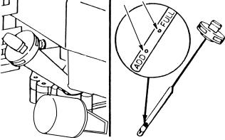
Check Oil Level
Fill crankcase with SAE 30 oil until oil level reaches FULL mark on dipstick as shown in Figure 1. The maximum crankcase capacity is 22 ounces (0.65 Liter). On models equipped with an oil filter, the maximum crankcase capacity is 26 ounces (0.78 Liter). Use any high quality detergent oil having the American Petroleum Institute (API) ªservice classificationºÐSF, SG SH, or SJ.
Before each use or every five hours, ensure oil level is between ADD and FULL marks on dipstick (Fig. 1). Add oil if level is low.
1.Position mower on level surface and clean around oil dipstick.
2.Remove dipstick by rotating cap counterclockwise 1/4 turn (Fig. 1).
3.Wipe dipstick and insert it into oil fill tube. Rotate cap clockwise 1/4 turn. Then remove dipstick and check level of oil (Fig. 1). If level is low, add only enough oil to raise level to FULL mark on dipstick. DO NOT FILL ABOVE
FULL MARK BECAUSE ENGINE COULD BE DAMAGED WHEN STARTED. POUR OIL SLOWLY.
4.Insert dipstick into oil fill tube and rotate cap clockwise 1/4 turn to lock (Fig. 1).
3 4
Fig. 1 ± Checking Oil Level
1. |
Oil fill tube |
3. |
ADD mark |
2. |
Dipstick |
4. |
FULL mark |
|
|
|
|
Change Oil
Change the oil after the first 5 operating hours. Thereafter, change the oil every 50 operating hours or every season. More frequent oil changes are required when operating engine under a heavy load, or when used in dusty, dirty, or hot conditions.
Replace the oil filter (on models so equipped) every 100 hours or yearly, whichever occurs first.
There are two methods of changing engine oil, the drain plug method and the oil fill tube method. Both work equally well.
GTS 200 |
5 |
General Information |
Change OilÐDrain Plug Method
1.Run engine at least 5 minutes to warm the oil. Warm oil drains more easily and more of the contaminants are removed.
2.Remove oil drain plug (Fig. 2). Drain oil into a pan.
1
Fig. 2 ± Drain Plug Location
1. Oil drain plug
3.If replacing the oil filter (on models so equipped), do so at this time.
4.Install drain plug snugly.
5.Remove dipstick and refill slowly with new oil of proper service classification and viscosity grade.
6.Start and run engine at idle. Check for oil leaks.
7.Stop engine. Recheck oil level and add oil if required.
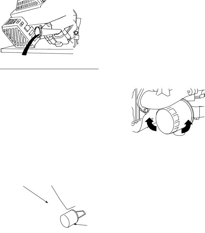
Change OilÐOil Fill Tube Method
1.Stop engine and wait for all moving parts to stop. Pull wire off spark plug.
2.Remove grass bag. Drain gasoline from fuel tank.
3.Remove dipstick from oil fill tube and place a drain pan next to left side of mower.
4.Tip mower on its left side, allowing oil to drain into drain pan (Fig. 3).
1
2
m±3848
Fig. 3
1. Oil fill tube |
2. Oil filter |
|
|
5.If replacing the oil filter (on models so equipped), do so at this time.
6.When oil is drained, return mower to upright position and add fresh oil to engine. Refer to Oil in this section.
Approximate Crankcase Oil Capacity (Dry)
Specifications
Without oil filter . . . . . 22 oz.
.65 Liter
With oil filter . . . . . . . . 26 oz.
.78 Liter
Change Oil Filter
(on models so equipped)
Change filter every 100 hours. Before installing new filter, lightly oil filter gasket with fresh clean engine oil. Screw filter clockwise by hand until gasket contacts filter adapter. Tighten 1/2 to 3/4 turn farther. Add fresh oil. Then, start and run engine at idle for 30 seconds and stop engine. Recheck oil level and add oil if required. Restart engine and check for oil leaks, Fig. 4.
1 |
2 |
Fig. 4 ± Remove and Install Oil Filter
1. Install |
2. Remove |
|
|
General Information |
6 |
GTS 200 |

Gasoline
Use clean, fresh, lead-free gasoline (including oxygenated or reformulated gasoline) with an octane rating of 87 or higher. To ensure freshness, purchase only the quantity of gasoline that can be used in 30 days. Using unleaded gasoline results in fewer combustion chamber deposits and longer spark plug life.
Engines certified to comply with California and U.S. EPA emission regulations for ULGE engines are certified to operate on regular unleaded gasoline, include EM and TWC (if so equipped) emission control systems, and do not include any user adjustable features.
IMPORTANT: Do not use methanol, gasoline containing methanol, gasohol containing more than 10% ethanol, premium gasoline, or white gas. Using these fuels can damage the engine's fuel system.
DANGER
POTENTIAL HAZARD
•In certain conditions gasoline is extremely flammable and highly explosive.
WHAT CAN HAPPEN
•A fire or explosion from gasoline can burn you, others, and cause property damage.
HOW TO AVOID THE HAZARD
•Use a funnel and fill the fuel tank outdoors, in an open area, when the engine is cold. Wipe up any gasoline that spills.
•Do not fill the fuel tank completely full. Add gasoline to the fuel tank until the level is 1/4º to 1/2º (6 mm to 13 mm) below the bottom of the filler neck. This empty space in the tank allows gasoline to expand.
•Never smoke when handling gasoline, and stay away from an open flame or where gasoline fumes may be ignited by a spark.
•Store gasoline in an approved container and keep it out of the reach of children.
•Never buy more than a 30-day supply of gasoline.
DANGER
POTENTIAL HAZARD
•When fueling, under certain circumstances, a static charge can develop, igniting the gasoline.
WHAT CAN HAPPEN
•A fire or explosion from gasoline can burn you and others and cause property damage.
HOW TO AVOID THE HAZARD
•Always place gasoline containers on the ground away from your vehicle before filling.
•Do not fill gasoline containers inside a vehicle or on a truck or trailer bed because interior carpets or plastic truck bed liners may insulate the container and slow the loss of any static charge.
•When practical, remove gas±powered equipment from the truck or trailer and refuel the equipment with its wheels on the ground.
•If this is not possible, then refuel such equipment on a truck or trailer from a portable container, rather than from a gasoline dispenser nozzle.
•If a gasoline dispenser nozzle must be used, keep the nozzle in contact with the rim of the fuel tank or container opening at all times until fueling is complete.
Use a fuel stabilizer/conditioner regularly during operation and storage. A stabilizer/conditioner cleans the engine during operation and prevents gum±like varnish deposits from forming in the engine during storage.
IMPORTANT: Do not use fuel additives other than a fuel stabilizer/conditioner. Do not use fuel stabilizers with an alcohol base such as ethanol, methanol, or isopropanol.
1.Clean the area around the fuel tank cap.
2.Remove the cap from the fuel tank.
3.Using unleaded, regular gasoline, fill the tank to within 1/4 to 1/2 in. (6 to 13mm) from the top of the tank.
IMPORTANT: Do not fill the tank with gasoline into the filler neck. This space is for expansion of fuel. Do not fill the tank completely full.
4.Install the fuel tank cap.
5.Wipe up any spilled gasoline.
Cooling System
Grass particles, chaff, or dirt can clog the air cooling system, especially after prolonged service in very dusty conditions or when cutting dry grass. Continued operation with a clogged cooling system can cause severe overheating and possible engine damage. Figures 5 and 6 show the areas to be cleaned.
GTS 200 |
7 |
General Information |

This should be a regular maintenance operation, performed yearly or every 100 hours, whichever comes first and more often when dust or when airborne debris is present.
 1
1
Fig. 5 ± Static Screen
1. Static screen
1 2
Fig. 6 ± Cylinder Fins and Ducting
1. Ducting |
2. Cylinder fins |
|
|
Air Cleaner ± General
A properly serviced air cleaner protects internal parts of the engine from dust particles in the air. If air cleaner instructions are not carefully followed, dirt and dust which should be collected in the air cleaner will be drawn into the engine and become a part of the oil film, which is very detrimental to engine life; dirt in the oil forms an abrasive mixture which wears moving parts instead of protecting them.
Air Cleaner Service
Normally, clean the air cleaner pre±cleaner after every
25 operating hours or every season. Clean or replace the paper cartridge after every 100 hours or every season. More frequent cleaning is required when mower is operated in dusty or dirty conditions. Replace air cleaner parts, if very dirty.
IMPORTANT: Do not operate engine without air filter elements; extreme engine wear or damage will occur.
Note: Tipping mower on wrong side to service underside of mower may cause damage to air filters.
1. Stop engine and pull wire off spark plug (Fig. 7).
1 2 m±3662
Fig. 7 ± Remove Spark Plug Wire Prior to Service
1. Primer 2. Spark plug wire
2.Loosen two (2) knobs securing air cleaner cover to engine (Fig. 8).
1
2
4
3
m±3664
Fig. 8 ± Air Cleaner Service
1. |
Knob |
3. |
Foam pre±cleaner |
2. |
Cover |
4. |
Paper cartridge |
|
|
|
|
3.Lift cover off. Clean cover thoroughly.
4.Carefully remove pre±cleaner. If pre±cleaner is dirty, carefully wash it in a solution of liquid soap and warm water. Rinse in clear water. Allow to dry thoroughly before using.
5.If paper cartridge is dirty, clean the paper filter by tapping it gently on a flat surface. If very dirty, replace cartridge.
IMPORTANT: Do not oil pre±cleaner or paper cartridge. Do not use pressurized air to clean paper cartridge.
6.Reinstall pre±cleaner over paper cartridge. Reinstall air cleaner cover and tighten securely in place with two (2) knobs.
General Information |
8 |
GTS 200 |
Tune-Up Procedure
By performing the following steps you will either be sure that the engine is functioning properly or will know what repairs should be made.
These steps are also covered in the Overhaul Procedure and will normally be performed as a part of complete overhaul.
Carbon deposits in combustion chamber should be removed every 100 to 300 hours of use (more often when run at steady loads), or whenever cylinder head is removed.
Step No.
1.Remove air cleaner, check for proper servicing. Replace if damaged or dirty.
2.Check oil level and drain oil.
3.Remove blower housing, inspect rewind assembly.
4.Clean cooling fins and entire engine.
5.Remove carburetor, disassemble, and inspect for wear or damage. Wash in solvent. Replace parts as necessary and assemble. Set initial adjustment.
6.Inspect intake elbow or carburetor spacer for damaged gaskets.
7.Check governor, linkage, and springs for damage, wear, also check adjustment.
8.Clean fuel tank and lines.
9.Remove flywheel. Check for oil seal leakage, both flywheel and PTO sides. Check flywheel key.
10.Check armature coil. Inspect all wires for breaks and/or damaged insulation. Be sure lead wires do not touch flywheel. Check stop switch and lead(s).
11.Remove oil, debris, and nicks from flywheel and crankshaft tapers.
12.Install flywheel and set air gap. Check for spark with Briggs & Stratton Tool #19051 or #19368 ignition tester.
13.Remove spark plug and cylinder head.
14.Inspect valves for seating.
15.Clean carbon from cylinder head and piston.
16.Replace gaskets and install cylinder head. Tighten to specified torque. Adjust valve clearance. Set spark plug gap or replace plug if necessary.
17.Replace gaskets and install carburetor
18.Adjust remote control linkage and cable, if used, for correct operation.
19.Check muffler for restrictions or damage.
20.Replace oil and fuel.
21.Run engine and adjust carburetor mixture and engine Top No Load RPM.
GTS 200 |
9 |
General Information |
Overhaul Procedure
The Overhaul Procedure which follows is intended to help you become accustomed to a systematic method of repairing Toro GTS 200 OHV engines. Naturally these steps could be rearranged in different order but efficiency is obtained when the repair operations are performed in the same sequence every time.
The Overhaul Procedure can also be used as an index. For information on how to perform most operations listed, refer to the section number or operation.
Disassemble |
Section |
Beginning |
Page |
||
|
|
|
Check compression |
Compression |
27 |
|
|
|
Drain oil ± Remove oil filter (when equipped) |
Lubrication |
47 |
|
|
|
Air cleaner |
General Information |
5 |
|
|
|
Fuel line, tank assembly and brackets, carburetor and linkage, carburetor |
Carburetion |
18 |
intake manifold or spacer |
|
|
|
|
|
Exhaust manifold, muffler |
Muffler |
59 |
|
|
|
Disassemble carburetor |
Carburetion |
18 |
|
|
|
Electric starter (12 V) Blower housing |
Electric Starter |
38 |
|
|
|
Breather and valve cover |
Lubrication |
47 |
|
|
|
Valves and springs, rocker arms, push rods, cylinder head and shields, |
Compression |
27 |
valve guides and seats |
|
|
|
|
|
Rewind starter |
Rewind Starter |
33 |
|
|
|
Flywheel |
Ignition |
14 |
|
|
|
Check crankshaft end play |
Crankshaft and Camshaft |
53 |
|
|
|
Remove burrs from crankshaft extension |
Crankshaft and Camshaft |
53 |
|
|
|
Crankcase cover or sump |
Crankshaft and Camshaft |
53 |
|
|
|
Mechanical governor parts |
Governor |
25 |
|
|
|
Cam gear and tappets |
Crankshaft and Camshaft |
53 |
|
|
|
Connecting rod and piston |
Pistons, Rings, and Rods |
49 |
|
|
|
Crankshaft |
Crankshaft and Camshaft |
53 |
|
|
|
Inspection |
Section |
Beginning |
Page |
||
|
|
|
Inspect carburetor choke, throttle shaft, and bushings for wear and |
Carburetion |
18 |
freedom of movement |
|
|
|
|
|
Inspect and test ignition coil |
Ignition |
14 |
|
|
|
Crankshaft ± inspect and check |
Crankshaft and Camshaft |
53 |
|
|
|
Oil pump ± inspect and check, if so equipped |
Lubrication |
47 |
|
|
|
Cylinder ± check bore, main bearing |
Cylinder and Bearings |
56 |
|
|
|
Check piston, rings, connecting rod, and piston pin |
Pistons, Rings, and Rods |
49 |
|
|
|
General Information |
10 |
GTS 200 |
Repairs |
Section |
Beginning |
Page |
||
|
|
|
Clean/replace parts as required |
|
|
|
|
|
Replace block or short block if cylinder is over allowable dimension |
Cylinder and Bearings |
56 |
|
|
|
Replace valve guides ± intake or exhaust, if required |
Compression |
27 |
|
|
|
Reface valves and seats and lap, if required |
Compression |
27 |
|
|
|
Replace ignition armature, if required |
Ignition |
14 |
|
|
|
Replace throttle shaft bushings, if required |
Carburetion |
18 |
|
|
|
Repair carburetor |
Carburetion |
18 |
|
|
|
Replace rewind starter spring and rope (if so equipped) |
Rewind Starter |
33 |
|
|
|
Replace main bearings and seals, if required |
Cylinder and Bearings |
56 |
|
|
|
Reassemble |
Section |
Beginning |
Page |
||
|
|
|
Crankshaft |
Crankshaft and Camshaft |
53 |
|
|
|
Piston, piston pin, connecting rod, and rings |
Pistons, Rings, and Rods |
49 |
|
|
|
Tappets, cam gear |
Crankshaft and Camshaft |
53 |
|
|
|
Oil pump, if so equipped |
Lubrication |
47 |
|
|
|
Mechanical governor |
Governor |
25 |
|
|
|
Crankcase cover or sump |
Crankshaft and Camshaft |
53 |
|
|
|
Breather |
Lubrication |
47 |
|
|
|
Flywheel, starter cup, and fan |
Ignition |
14 |
|
|
|
Ignition armature assembly |
Ignition |
14 |
|
|
|
Adjust ignition armature to flywheel air gap |
Ignition |
14 |
|
|
|
Check spark |
Ignition |
14 |
|
|
|
Electric starter (12 V) |
Electric Starter |
38 |
|
|
|
Valves, valve stem seals, springs, retainers, rocker arms |
Compression |
27 |
|
|
|
Cylinder head and push rods |
Compression |
27 |
|
|
|
Adjust valve clearance |
Compression |
27 |
|
|
|
Valve cover |
Compression |
27 |
|
|
|
Spark plug ± adjust gap to .020º |
Ignition |
14 |
|
|
|
Exhaust manifold, mufflers |
Muffler |
59 |
|
|
|
Intake manifold |
Carburetion |
18 |
|
|
|
Carburetor and linkage and governor controls |
Governor Controls, |
22 |
|
Carburetor Linkage, and |
|
|
Flywheel Brake |
|
|
|
|
Check and adjust mechanical governor |
Governor |
25 |
|
|
|
Blower housing and rewind starter |
Ignition |
14 |
|
|
|
Fuel filter, tank, and line |
Carburetion |
18 |
|
|
|
Clean/replace and assemble air cleaner |
General Information |
5 |
|
|
|
Fill crankcase with oil, fill with gas, start engine |
General Information |
5 |
|
|
|
Adjust carburetor |
Carburetion |
18 |
|
|
|
Set governor to obtain correct engine speed (remote controls) |
Governor |
25 |
|
|
|
Spray paint engine parts and apply decals |
|
|
|
|
|
GTS 200 |
11 |
General Information |

Check-Up
Most complaints concerning engine operation can be classified as one or a combination of the following:
1.Will not start
2.Hard starting
3.Lack of power
4.Vibration
5.Overheating
6.High oil consumption
When the cause of malfunction is not readily apparent, perform a check of the compression, ignition, and carburetion systems. This check-up, performed in a systematic manner, can usually be done in a matter of minutes. It is the quickest and surest method of determining the cause of failure. This check-up will point out possible cause of future failures, which can be corrected at the time. The basic check-up procedure is the same for all engine models, while any variation, by model, will be shown under the subject heading.
Check Compression
See the section Compression for proper procedure.
If compression is poor, look for ±
1.Loose spark plug
2.Loose cylinder head bolts
3.Blown head gasket
4.Burned valves, valve seats
5.Insufficient valve clearance
6.Warped cylinder head or warped valve cover
7.Warped or worn valve stems and guides
8.Worn bore and/or rings
9.Broken connecting rod
Check Ignition (Using Engine Starter)
WARNING
BE SURE there is no fuel or fuel vapor present, which might be ignited by the spark and cause a fire or explosion.
Attach a spark tester to spark plug wire and ground the other end of the tester to the engine block. Warning: Do not remove spark plug. Spin the flywheel with the engine starter. If spark jumps the .166º (4.20mm) tester gap, you can assume the ignition system is performing satisfactorily. See the section Ignition for additional information.
If spark does not occur, look for ±
1.Shorted stop switch wire
2.Shorted stop switch
3.Ignition armature failure
4.Improperly operating interlock system
Note: If engine runs but misses during operation, a quick check to determine if ignition is or is not at fault can be made by inserting the spark tester between the ignition cable and the spark plug. A spark miss will be readily seen. See the Ignition section.
Check Carburetion
Before making a carburetion check, be sure the fuel tank has an ample supply of fresh, clean gasoline. Be sure that the shut-off valve is open and fuel flows freely through fuel line and filter before starting engine. Inspect and adjust the needle valve. Check to see that the choke closes completely. If engine will not start, remove and inspect the spark plug.
If plug is wet, look for ±
1.Over choking
2.Excessively rich fuel mixture
3.Water in fuel
4.Inlet needle stuck open
5.Clogged air cleaner
6.Fouled spark plug
If plug is dry, look for -
1.Leaking carburetor mounting gaskets
2.Gummy or dirty carburetor, fuel filter, fuel lines, shut-off valve or fuel tank
3.Inlet needle stuck shut
4.Inoperative fuel pump (if so equipped)
A simple check to determine if the fuel is getting to the combustion chamber through the carburetor is to remove the spark plug and pour a small quantity of gasoline through the spark plug hole. Replace the plug. If the engine fires a few times and then stops, look for the same conditions as for a dry plug.
Equipment Affecting Engine
Operation
What appears to be a problem with engine operation, such as hard starting, vibration, etc., may be the fault of the mower rather than the engine itself. Listed are the most common effects of equipment problems and what to look for as the most common cause.
General Information |
12 |
GTS 200 |
Hard Starting, or Will Not Start
1.Check remote control assembly for proper adjustment.
2.Check ignition system.
Vibration
1.Cutter blade bent ± Remove and replace.
2.Cutter blade out of balance ± Remove and balance.
3.Crankshaft bent ± Replace.
4.Worn blade coupling ± Replace if coupling allows blade to shift, causing unbalance.
5.Mounting bolts loose ± Tighten.
6.Mounting deck or plate cracked ± Repair or replace.
7.Damaged belts or pulleys.
Power Loss
1.Grass cuttings build-up under deck.
2.No lubrication in transmission or gear box.
3.Dull blade.
4.Excessive drive belt tension may cause excess bearing wear or seizure.
Noise
1.BBC system problems (if so equipped).
2.No lubricant in transmission or gear box.
3.Worn drive belts.
4.Worn bearings.
GTS 200 |
13 |
General Information |
Ignition
Contents
Check Ignition . . . . . . . . . . . . . . . . . . . . . . . . . . . . . . . . . . . 14
Check For Spark Miss . . . . . . . . . . . . . . . . . . . . . . . . . 14
Spark Plug . . . . . . . . . . . . . . . . . . . . . . . . . . . . . . . . . . . . . . 15
Spark Plug Maintenance . . . . . . . . . . . . . . . . . . . . . . . 15
Remove Ignition Armature . . . . . . . . . . . . . . . . . . . . . 15
Remove Flywheel . . . . . . . . . . . . . . . . . . . . . . . . . . . . . . . . 15
Inspect Flywheel Key, Keyways, Flywheel,
and Crankshaft . . . . . . . . . . . . . . . . . . . . . . . . . . . . . . . . . 16
Install Flywheel . . . . . . . . . . . . . . . . . . . . . . . . . . . . . . . . . . 16
Install Flywheel . . . . . . . . . . . . . . . . . . . . . . . . . . . . . . 16
Install Ignition Armature . . . . . . . . . . . . . . . . . . . . . . . 16
Adjust Ignition Armature Air Gap . . . . . . . . . . . . . . . 17
Specifications . . . . . . . . . . . . . . . . . . . . . . . . . . . . . . . . . . . . 17
WARNING
TO PREVENT accidental starting, the spark plug wire must be removed from spark plug and grounded, failure to do so can cause personal injury.
WARNING
DO NOT remove spark plug when checking ignition. A fire or explosion may occur.
WARNING
FLYWHEEL KICKBACK can occur if the flywheel key is sheared and bodily injury may occur.
Check Ignition
1.Connect spark plug wire to Spark Tester, Fig. 9.
2.Operate starter and observe spark gap in tester. If spark jumps tester gap, ignition is good.
Note: Flywheel must rotate at 350 RPM, minimum.
Note: Spark will be observed.
1
2 Fig. 9 ± Checking for Spark
1. Spark plug wire |
2. Spark tester, Briggs & |
|
Stratton Tool #19051 or |
|
#19368 |
|
|
Check For Spark Miss
1.Install Briggs & Stratton Tool #19051 or #19368, Spark Tester, in series with spark plug lead and spark plug, Fig. 10.
3
2
1
Fig. 10 ± Running Check
1. Spark plug lead |
3. Spark plug |
2.Spark tester, Briggs & Stratton Tool #19051 or
#19368
2.Start and run engine.
3.If spark jumps tester gap regularly, but miss continues, problem is spark plug, compression, or fuel system.
Ignition |
14 |
GTS 200 |
Spark Plug
The recommended spark plug is:
Spark Plug Type |
Brand |
|
|
|
|
Resistor Long Plug |
Champion |
|
RC12YC |
||
|
Note: In some areas, local law requires the use of a resistor spark plug to suppress ignition signals. If an engine was originally equipped with a resistor spark plug, be sure to use the same type of spark plug for replacement.
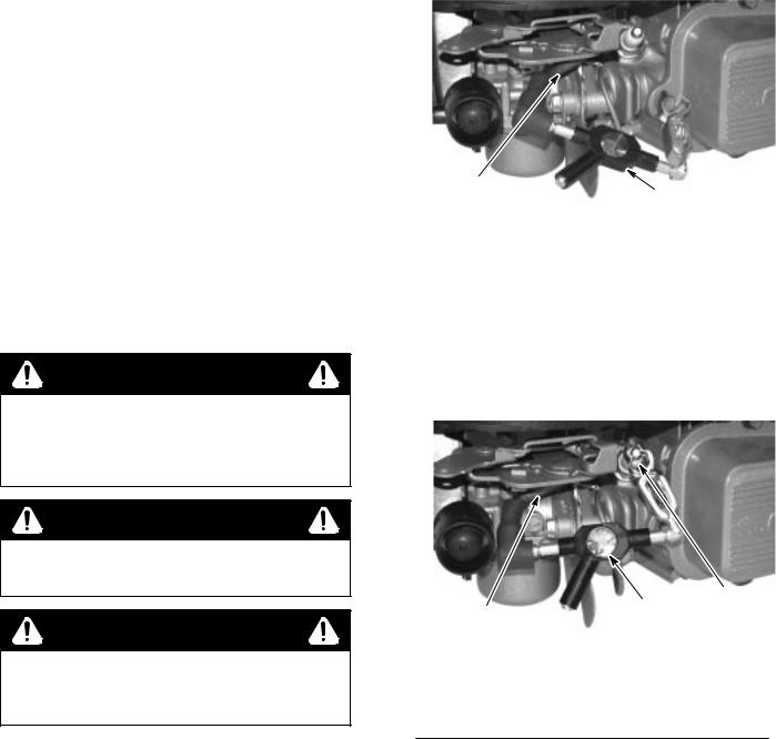
Spark Plug Maintenance
Set gap at .020º (0.51mm), Fig. 11. If electrodes are burned away, or porcelain is cracked or fouled, replace with a new plug.
Note: Do not use abrasive cleaning machines.
1
Fig. 11 ± Adjusting Spark Plug Gap
1. .020º (0.51mm) wire gauge
Remove Ignition Armature
1.Remove blower housing.
2.Remove armature screws, disconnect stop wire, and lift off armature, Fig. 12.
|
1 |
|
3 |
|
|
2 |
4 |
|
|
|
|
|
Fig. 12 ± Removing Ignition Armature |
||
1. |
Ignition armature |
3. |
Stop switch wire |
2. |
Screws |
4. |
Terminal |
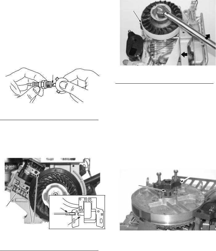
Remove Flywheel
1.Remove blower housing.
2.Use flywheel holder to hold flywheel from turning, Fig. 13.
1
Fig. 13 ± Removing Flywheel Nut
1. Flywheel holder Briggs & Stratton Tool #19372
3.Use socket and breaker bar to remove flywheel nut.
Note: Remove ignition armature before removing flywheel.
4.Thread flywheel nut onto crankshaft until top of nut is flush with crankshaft threads or slightly 1.5mm (1/16º) above end of threads.
5.Attach flywheel puller.
6.Turn puller screws into flywheel puller holes until screws bottom.
7.Turn lower nuts down until flywheel puller body rests firmly on flywheel nut.
8.Then turn upper nuts down onto puller body. Turn both nuts equally until flywheel pops loose, Fig. 14.
 2
2
1
Fig. 14 ± Removing Flywheel
1. Flywheel nut |
2. Briggs & Stratton Tool |
|
#19069 flywheel puller |
|
|
GTS 200 |
15 |
Ignition |
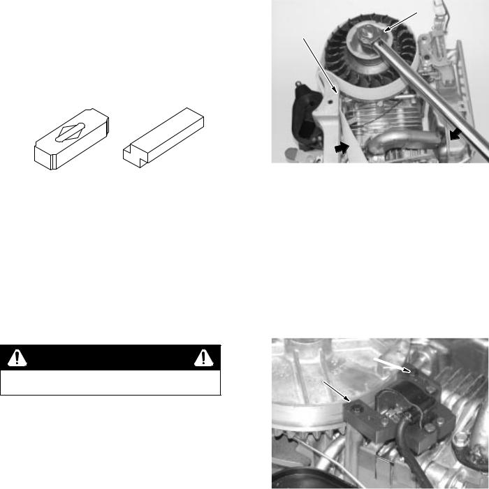
Inspect Flywheel Key, Keyways,
Flywheel, and Crankshaft
Inspect flywheel key for partial or complete shearing. If sheared, replace, Fig. 15. Flywheel should be inspected for cracks, burrs on taper or keyway, and distortion of keyway. Check taper of crankshaft for burrs, rust, oil, or other damage. Check cooling fan or flywheel for broken fins. If parts are damaged, replace with new parts.
1 |
2 |
Fig. 15 ± Inspect Flywheel Key
1. OK |
2. Replace |
|
|
Install Flywheel
Install Flywheel
1.Clean flywheel taper and crankshaft taper of all grease, oil and dirt.
2.Slide flywheel onto crankshaft and line up both keyways. Insert flywheel key into both keyways.
Note: DO NOT use a steel key under any circumstances.
WARNING
DO NOT use impact wrenches to install flywheel.
3.Install starter cup, cooling fan, and flywheel nut or screw.
4.Use flywheel holder to hold flywheel from turning, Fig. 16.
5.Install flywheel nut or screw.
6.Use socket and torque wrench to tighten flywheel nut or screw.
7.Torque as listed in Table No. 1, Page 17.
2
1
Fig. 16 ± Torquing Flywheel
1. Briggs & Stratton Tool |
2. Cup |
#19321, flywheel holder or |
|
Tool # 19372 flywheel |
|
strap wrench |
|
|
|
Install Ignition Armature
1.Install stop switch wire on armature, Fig. 12, Page 15.
2.Turn flywheel so magnet is away from armature.
3.Install armature and mounting screws, Fig. 17.
Note: Mounting holes in armature are slotted.
2 
1
Fig. 17 ± Installing Armature
1. Ignition armature |
2. Tighten one screw |
|
|
4.Push armature away from flywheel as far as possible and tighten one screw to hold armature in place.
Ignition |
16 |
GTS 200 |
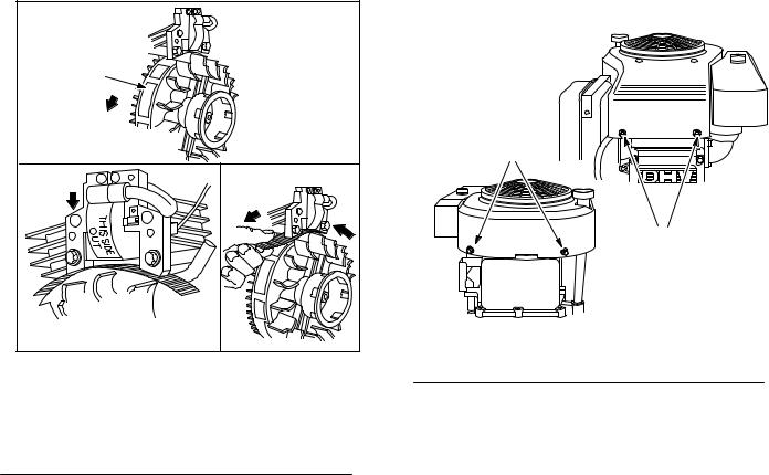
Adjust Ignition Armature Air Gap |
3. See Table No. 1, Page 17 for armature air gap. Loosen |
1. Rotate flywheel until magnet is under armature |
mounting screw so magnet will pull armature down against |
thickness gauge. |
|
laminations. |
|
2. Place thickness gauge, Table No. 1, Page 17, between |
4. Torque both mounting screws to 25 in. lbs. (3.0Nm) Rotate |
flywheel to remove thickness gauge. |
|
magnet and armature laminations, Fig. 18. |
5. Install outer blower housing and screws and torque screws |
|
|
|
to 85 in. lbs., (10.0Nm) Fig. 19. |
1 |
|
2 |
|
|
1 |
3 |
|
5 |
4 |
|
|
|
1 |
|
Fig. 19 ± Installing Outer Blower Housing |
1. Torque screws to 85 in. lbs.
Fig. 18 ± Adjusting Armature Air Gap
1. |
Magnet |
4. |
Turn |
2. |
Turn magnet away from |
5. |
Roll out gauge |
|
armature |
|
|
3.Armature down; gauge stock in place
Specifications
Table No. 1
Armature Air Gap |
Flywheel Puller |
Flywheel Holder |
Flywheel Nut Torque |
Briggs & Stratton Tool # |
Briggs & Stratton Tool # |
||
|
|
|
|
.006º ± .012º |
19069 |
19372 |
60 ft. lbs. |
(0.15 ± 0.30mm) |
|
|
(81.0Nm) |
|
|
|
|
GTS 200 |
17 |
Ignition |
 Loading...