


Toastmaster®
A Middleby Company
OWNER'S OPERATING
& INSTALLATION
MANUAL
AM24, AM36 & AM48
ACCU-MISER GRIDDLES
AM24
Toastmaster® • 1400 Toastmaster Drive • Elgin, IL 60120 • (708)741-3300 • FAX (708)741-4406
A Middleby Company
Middleby Corp 24 Hour Service Hotline 1-800-238-8444
Part No. 32025
Price $15.00
P 2/95

Toastmaster®
GRIDDLE LIMITED WARRANTY
All equipment manufactured by Toastmaster Commercial which is sold under the “Toastmaster” trademark and used for commercial purposes is warranted against defects in materials and workmanship. The warranty period runs 12 months from the original date of installation. This 12 month warranty period may not run beyond 18 months from the original date of purchase and is for the benefit of the original purchaser only. ALL OTHER WARRANTIES, EXPRESS OR IMPLIED, STATUTORY OR OTHERWISE, INCLUDING WITHOUT LIMITATION ANY IMPLIED WARRANTY OR MERCHANTABILITY OR FITNESS FOR PURPOSE ARE EXCLUDED. Seller shall in no event be liable for direct, indirect or consequential damages in connection with Toastmaster Commercial products.
Seller’s obligation under this warranty is limited to the repair of defects without charge, by a factory authorized service agency or one of its sub-service agencies. Such repair service will be provided on customer’s premises except in the case of portable products.
Models that are considered portable (devices with cord and plugs) including conveyor toasters must be taken or shipped to the closest authorized service agency, transportation charges prepaid.
This warranty is not effective if damage occurs because of accident, carelessness, improper installation, lack of proper set-up supervision when required or because equipment is installed on a different voltage, steam or gas service then designated on the equipment nameplate, or if the equipment is installed or operated in any manner contrary to the installation and operation instructions. In these cases, repairs will be made at a reasonable cost. Work performed by unauthorized personnel or service agencies voids this warranty.
Authorized service agencies are located in principal cities throughout the world. Please consult your classified telephone directory, your food service equipment distributor, or write the Factory Service Department, Toastmaster® , 1400 Toastmaster Drive, Elgin, Illinois 60120, for information and other details concerning service of this warranty.
© 1995 Toastmaster
Toastmaster • 1400 Toastmaster Dr. • Elgin, IL 60120-9272 • (708) 741-3300 • FAX (708) 741-4406
Middleby Corp 24 Hour Service Hotline 1-800-238-8444
i
IN CASE OF FIRE
1.De-energize griddle at disconnect switch. This will cut off power to the heating elements allowing griddle to cool. This reduces the flash point temperature making it easier to stop the fire.
2.Cover the affected area with a heavy blanket or canvas. Play the fire extinguisher nozzle over the blanket or cover to seal off air thus smothering the fire.
CAUTION:
Do not attempt to fight a grease fire by playing the nozzle of the fire extinguisher directly on the burning grease. The force will cause the burning grease to be sprayed to adjoining equipment making it difficult to contain the fire. Only use a fire extinguisher filled with CO2 which is for liquids and oils and suitable for electric powered equipment.
RETAIN THIS MANUAL FOR FUTURE REFERENCE
This manual provides detailed information for installation and operation of your new Accu-Miser griddle. It also contains some information to assist the operator in diagnosing problems in the event of a malfunction. This manual is an important tool for the operator and should be kept readily available.
FOR YOUR SAFETY
DO NOT STORE OR USE GASOLINE
OR OTHER FLAMMABLE VAPORS OR LIQUIDS
IN THE VICINITY OF THIS OR ANY OTHER APPLIANCE
NOTICE
Using any parts other than genuine Toastmaster factory parts relieves the manufacturer of all liability.
NOTICE
Toastmaster (Manufacturer) reserves the right to change specifications and product design without notice. Such revisions do not entitle the buyer to corresponding changes, improvements, additions or replacements for previously purchased equipment.
ii
TABLE OF CONTENTS |
|
SECTION 1 |
|
DESCRIPTION ........................................................................................ |
1 |
Component Location ................................................................................. |
2 |
Specification Chart .................................................................................... |
3 |
Electrical Specification Chart ..................................................................... |
4 |
Dimension Drawing ................................................................................... |
5 |
SECTION 2 |
|
INSTALLATION ........................................................................................ |
7 |
A. Inspect For Shipping Damage .............................................................. |
7 |
B. Unpacking Griddle ................................................................................ |
7 |
C. Installing Griddle on Counter ................................................................ |
7 |
D. Installing Griddle on Accessory Stand .................................................. |
8 |
E. Electrical Connection ............................................................................ |
10 |
F. Initially Clean the Griddle ...................................................................... |
11 |
G. Test the Installation .............................................................................. |
11 |
SECTION 3 |
|
OPERATION ........................................................................................ |
13 |
Location and Function of Controls ............................................................. |
13 |
A. Controls ........................................................................................ |
14 |
B. Seasoning the Griddle .................................................................... |
15 |
C. Operating Hints and Safety ............................................................ |
15 |
D. Daily Operation and Maintenance .................................................. |
15 |
E. Operation Troubleshooting ............................................................. |
16 |
F. Time and Temperature Guide ......................................................... |
17 |
G. Cooking Capacities ........................................................................ |
18 |
SECTION 4 |
|
PARTS LIST ........................................................................................ |
19 |
Overall Parts List ....................................................................................... |
20 |
SECTION 5 |
|
ELECTRICAL SCHEMATIC ............................................................................ |
23 |
AM24 Wiring Diagram & Schematic .......................................................... |
24 |
AM36 Wiring Diagram & Schematic .......................................................... |
26 |
AM48 Wiring Diagram & Schematic .......................................................... |
28 |
iii
|
SECTION 1 - DESCRIPTION |
|
|
SECTION 1 |
|
|
DESCRIPTION |
|
ACCU-MISER (AM) SERIES GRIDDLES ARE: |
|
|
• Electrically heated |
• Heated by infrared emitter panels |
|
• Counter top mounted |
• Thermostat solid state controller |
|
MODELS:
•AM24 (24" wide)
•AM36 (36" wide)
•AM48 (48" wide)
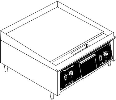
INFRARED HEAT PANELS.
The griddle employs infrared cooking technology. Infrared heat panels are placed below the griddle plate. These panels are 12" wide, which means an AM24 will accommodate 2 panels, an AM36 will accommodate 3 panels and etc. A thermostatic solid state controller for each 12" zone accurately maintains set griddle cooking temperatures for consistent and repeatable results. The thermostats have a range of 150°F (83°C) to 450°F (232°C). The griddle provides uniform heat distribution across the griddle surface.
FEATURES:
•Griddle On/Off switch.
•Thermostat Control with Heating Indicator Light (Red).
•The griddle features stainless steel front, sides and back.
•The griddle is equipped with a grease trough and a large grease drawer.
•The Toastmaster® AM Series Griddles are supplied with four 4" adjustable legs.
IMPORTANT!: For all installations the legs or the optional stand must be used to validate the warranty.
Figure 1-1
1
SECTION 1 - DESCRIPTION
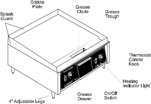
Component Location
Figure 1-2
2
SECTION 1 - DESCRIPTION
|
|
NOTICE |
|
|
Toastmaster (Manufacturer) reserves the right to change specifications and product design |
||
|
without notice. Such revisions do not entitle the buyer to corresponding changes, improve- |
||
|
ments, additions or replacements for previously purchased equipment. |
||
|
|
|
|
|
|
|
|
|
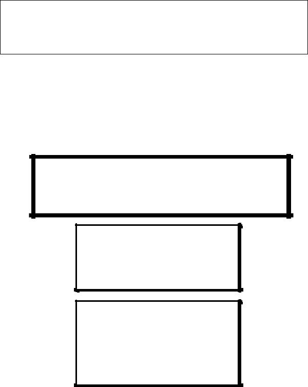
AM Series Griddles Specification Chart |
|
|
|
|
|
|
Griddle Plate Dimensions - |
AM24 |
23-7/8" (606 mm) W x 24" (610 mm) D |
|
|
AM36 |
35-7/8" (911 mm) W x 24" (610 mm) D |
|
|
AM48 |
47-3/4" (1213 mm) W x 24" (610 mm) D |
|
|
|
|
|
Overall Dimensions - |
AM24 |
24" (610 mm)W x |
|
|
|
28-1/2" (724 mm)D x 15" (381 mm)H |
|
|
AM36 |
36" (914 mm)W x |
|
|
|
28-1/2" (724 mm)D x 15" (381 mm) H |
|
|
AM48 |
47-15/16" (1218 mm)W x |
|
|
|
28-1/2" (724 mm)D x 15" (381 mm) H |
|
|
|
|
|
Net Weight - |
AM24 |
120 lbs. (54 kgm) |
|
|
AM36 |
222 lbs. (101 kgm) |
|
|
AM48 |
275 lbs. 125 kgm) |
|
|
|
|
|
Shipping Weight - |
AM24 |
140 lbs. (63 kgm) |
|
|
AM36 |
242 lbs. (110 kgm) |
|
|
AM48 |
300 lbs. (136 kgm) |
|
|
|
|
|
Shipping Dimensions - |
AM24 |
28-1/2" (724 mm)W x |
|
|
|
33-1/2" (851 mm)D x 17-1/2" (445 mm)H |
|
|
AM36 |
40-1/2" (1029 mm)W x |
|
|
|
33" (838 mm)D x 16-1/2" (419 mm) H |
|
|
AM48 |
52-1/2" (1334 mm)W x |
|
|
|
31-1/2" (800 mm)D x 16-1/2" (419 mm) H |
|
|
|
|
|
Average Operating kw |
|
Refer to Electrical Data Chart on following page |
|
|
|
|
|
Allowable Temperature Ranges |
150°F (83°C) to 450°F (232°C) |
|
|
|
|
|
|
Heat Source |
|
Infrared heat emitter panels |
|
|
|
One 12" emitter panel for each 12" of griddle width |
|
|
|
|
|
Griddle |
|
3/8" thick, uniform heat distribution design |
|
|
|
|
|
Grease Trough |
|
3-1/2" |
|
|
|
|
|
Outer Body Steel |
|
Front, 16 gauge stainless steel |
|
|
|
Sides, 20 gauge stainless steel |
|
|
|
|
|
3
SECTION 1 - DESCRIPTION
Griddle Electrical Specification Chart
|
Voltage |
Total |
Loading kW/Phase |
Nominal Amps/Line Wire |
Minimum |
|
Breaker |
|||||||
|
|
|
|
|
|
|
|
|
|
Supply Wire |
|
Rating* |
||
|
|
|
|
|
|
|
|
|
|
(AWG) Gauge* |
|
|
|
|
|
|
kW |
|
3 Ph |
|
|
3 Ph |
|
1 Ph |
3 Ph |
1 Ph |
3 Ph |
|
1 Ph |
|
|
|
|
|
|
|
|
|
|
|
|
|
|
|
|
|
|
X-Y |
Y-Z |
X-Z |
X |
Y |
Z |
|
|
|
|
|
|
AM24 |
208 |
6.2 |
3.1 |
3.1 |
-- |
15.0 |
26.0 |
15.0 |
30.0 |
10 |
8 |
25 |
|
30 |
|
240 |
6.2 |
3.1 |
3.1 |
-- |
13.0 |
22.5 |
13.0 |
26.0 |
10 |
10 |
30 |
|
30 |
|
|
|
|
|
|
|
|
|
|
|
|
|
|
|
AM36 |
208 |
9.3 |
3.1 |
3.1 |
3.1 |
26.0 |
26.0 |
26.0 |
45.0 |
10 |
6 |
25 |
|
40 |
|
240 |
9.3 |
3.1 |
3.1 |
3.1 |
22.5 |
22.5 |
22.5 |
39.0 |
10 |
8 |
30 |
|
45 |
|
|
|
|
|
|
|
|
|
|
|
|
|
|
|
AM48 |
208 |
12.5 |
6.2 |
3.1 |
3.1 |
39.7 |
39.7 |
26.0 |
60.1 |
8 |
4 |
35 |
|
50 |
|
240 |
12.5 |
6.2 |
3.1 |
3.1 |
35.9 |
35.9 |
22.5 |
52.0 |
8 |
6 |
40 |
|
60 |
|
|
|
|
|
|
|
|
|
|
|
|
|
|
|
* Provided for reference only. Consult national or local electrical codes.
4

SECTION 1 - DESCRIPTION
Griddle Dimension Drawing
5
SECTION 1 - DESCRIPTION
NOTES
6
SECTION 2 - INSTALLATION
SECTION 2 INSTALLATION
A.Inspect for Shipping Damage
All shipping containers should be examined for damage before and during unloading. This equipment was carefully inspected and packaged at the factory. The freight carrier has assumed responsibility for its safe transit and delivery. If equipment is received in damaged condition, either apparent or concealed, a claim must be made with the delivering carrier.
1.Apparent Damage or Loss - If damage or loss is apparent it must be noted on the freight bill or express receipt at the time of delivery, and it must be signed by the carrier’s agent (driver). If this is not done, the carrier may refuse the claim. The carrier will supply the necessary claim forms.
2.Concealed Damage or Loss - If damage or loss is NOT apparent until after equipment is uncrated, a request for inspection of concealed damage must be made with carrier within 15 days. The carrier will make an inspection and will supply necessary claim forms. Be certain to retain all contents plus external and internal packaging/crating materials for inspection.
B. Unpacking Griddle
1.The griddle will be delivered in a carton on a wooden pallet. Cut the banding straps that hold the carton in place and lift the carton up and off of the griddle.
2.Carefully turn the griddle upside down and remove the bolts that secure the pallet to the griddle.
Remove the pallet and discard.
C. Installing Griddle on Counter.
NOTE: If you are installing the griddle on an accessory stand go to Step D.
1. Installing Legs
Locate the four NSF approved 4" adjustable legs in the grease drawer.
With the grill still turned upside down install the four legs by threading them into the weldnuts on the leg mounting plates. Tighten the legs securely.
2. Leveling Griddle
Carefully lift the griddle onto its legs and place it on the counter in its permanent position. Level the griddle using a common carpenters level. Adjust the foot portion of the adjustable legs to level the griddle front-to-back and side- to-side.
7
 Loading...