


Toastmaster 3A81D, 3A20A, 3C84D, 3A80A, 3B20A User Manual
...
HOT FOOD SERVERS
FREE STANDING MODELS
3A81D
3B84D 3C84D, 3D8XD
BUILT-IN MODELS
3A20A, 3A80A 3B20A, 3B80A,3B84A 3C80A, 3C84A
Installation and
Operation
Instructions
2M-3102301, Rev. B, September 9, 2013
IL2087
|
|
|
|
|
|
|
|
|
|
|
|
|
|
|
|
|
|
|
|
|
|
|
|
|
|
|
|
|
|
|
|
|
|
|
|
|
|
|
|
|
|
|
|
|
|
|
|
|
|
|
|
|
|
|
|
|
|
|
|
3B84D |
3A20A |
|
|
|
|
|
|
|
|
|
|
|
|
|
|
|
|
|
|
|
|
|
|
|
|
|
|
|
|
|
|
|
|
|
|
|
|
|
SAFETY SYMBOLS
|
These symbols are intended to alert the user to the presence of |
|
|
important operating and maintenance instructions in the manual |
|
CAUTION |
accompanying the appliance. |
WARNING |
RETAIN THIS MANUAL FOR FUTURE REFERENCE
NOTICE
Using any part other than genuine Toastmaster factory supplied parts relieves the manufacturer of all liability.
Toastmaster reserves the right to change specifications and product design without notice. Such revisions do not entitle the buyer to corresponding changes, improvements, additions or replacements for previously purchased equipment.
Due to periodic changes in designs, methods, procedures, policies and regulations, the specifications contained in this sheet are subject to change without notice. While Toastmaster exercises good faith efforts to provide information that is accurate, we are not responsible for errors or omissions in information provided or conclusions reached as a result of using the specifications. By using the information provided, the user assumes all risks in connection with such use.
MAINTENANCE AND REPAIRS
Contact your local authorized service agent for service or required maintenance.
Please record the model number, serial number, voltage and purchase date in the area below and have it ready when you call to ensure a faster service.
Model No.
Serial No.
Voltage
Purchase Date
Authorized Service Agent Listing
Reference the listing provided with the unit or
for an updated listing go to:
Website: |
www.toastmastercorp.com |
Service@star-mfg.com |
|
Telephone: |
(314) 678-6347 |
The Service Help Desk
Business |
8:00 am to 4:30 p.m. Central Standard Time |
Hours: |
|
Telephone: |
(314) 678-6347 |
Fax: |
(314) 781-2714 |
Parts@star-mfg.com |
|
|
Service@star-mfg.com |
|
Warranty@star-mfg.com |
Website: |
www.star-mfg.com |
Mailing Address: Toastmaster
10 Sunnen Drive
St. Louis, MO 63143
U.S.A
2

TABLE OF CONTENTS
Page
Electrical Specifications. . . . . . . . . . . . . . . . . 1
Specifications . . . . . . . . . . . . . . . . . . 2
Features & Descriptions. . . . . . . . . . . . . . . . 3
Accessories. . . . . . . . . . . . . . . . . . 4
Installation
Inspection for Shipping Damage. . . . . . . . . . . 4
Unpacking. . . . . . . . . . . . . . . . . . 4
Installation of Free-Standing Models. . . . . . . . . 5
Installation of Built-In Units . . . . . . . . . . . . . 6
Initial Start-up. . . . . . . . . . . . . . . . . . 7
Operation
Location of Controls. . . . . . . . . . . . . . . . 8
Function of Controls. . . . . . . . . . . . . . . . 8
Operation. . . . . . . . . . . . . . . . . . 8
Shutdown. . . . . . . . . . . . . . . . . . 9
Pre-heating . . . . . . . . . . . . . . . . . . 9
Capacity Per Pan. . . . . . . . . . . . . . . . . 9
Recommended Temp & Humidity Setting. . . . . . . 10
Daily Cleaning. . . . . . . . . . . . . . . . . 10-11
Clean & Lubricate . . . . . . . . . . . . . . . . 11
Warranty. . . . . . . . . . . . . . . . . . 13
Exploded View & Parts List
Single Drawer Units. . . . . . . . . . . . . . . 14-16
Two, Three & Four Drawer, Single Controls . . . . . 18-21
Two, Three & Four Drawer, Individual Controls. . . . 22-24
ELECTRICAL SPECIFICATIONS
ELECTRICAL SPECIFICATIONS
Model No |
|
Voltage |
Watts |
Phasee |
Hz |
Power Cord |
|
|
|
|
|
|
|
|
|
7C-3A20AT09-120 |
|
3A20A |
120 |
.45 KW |
1 |
50/60 |
|
7C-3A80AT09-120 |
|
3A80A |
120 |
.45 KW |
1 |
50/60 |
|
7C-3A80AT72-240 |
|
3A80A |
240 |
.4/.54 KW |
1 |
50/60 |
|
7C-3A80AWC-120V |
|
3A80A |
120 |
.45 KW |
1 |
50/60 |
5-15P |
7C-3A81D-120KFC |
|
3A81D-KFC |
120 |
.45 KW |
1 |
50/60 |
|
7C-3A81DT09-120 |
|
3A81D |
120 |
.45 KW |
1 |
50/60 |
|
7C-3A81DT72-240 |
|
3A81D |
208/240 |
.45/.54 KW |
1 |
50/60 |
|
7C-3B20AT09-120 |
|
3B20A |
120 |
1.0 KW |
1 |
50/60 |
|
7C-3B20AT72-240 |
|
3B20A |
208/240 |
.9/1.2 KW |
1 |
50/60 |
|
7C-3B80AT09-120 |
|
3B80A |
120 |
1.0 KW |
1 |
50/60 |
|
7C-3B80AT72-240 |
|
3B80A |
208/240 |
.9/1.2 KW |
1 |
50/60 |
|
7C-3B80AWC-120V |
|
3B80A |
120 |
1.0 KW |
1 |
50/60 |
5-15P |
7C-3B84AT09-120 |
|
3B84A |
120 |
.9 KW |
1 |
50/60 |
|
7C-3B84AT72-240 / -SA |
|
3B84A |
208/240 |
.85/.98 KW |
1 |
50/60 |
|
7C-3B84DT09-120 |
|
3B84D |
120 |
.9 KW |
1 |
50/60 |
|
7C-3B84DT09-KFC |
|
3B84D-KFC |
120 |
.9 KW |
1 |
50/60 |
|
7C-3B84DT72-240 |
|
3B84D |
208/240 |
.85/.98 KW |
1 |
50/60 |
|
7C-3C80AT09-120 |
|
3C80A |
120 |
1.35 KW |
1 |
50/60 |
|
7C-3C80AT72-240 |
|
3C80A |
208/240 |
1.22/1.6 KW |
1 |
50/60 |
|
7C-3C84AT09-120 |
|
3C84A |
120 |
1.35 KW |
1 |
50/60 |
|
7C-3C84AT72-240 |
|
3C84D |
208/240 |
1.28/1.47 KW |
1 |
50/60 |
|
7C-3C84DT09-120 |
|
3C84D |
120 |
1.35 KW |
1 |
50/60 |
|
7C-3C84DT72-240 |
|
3B84D |
208/240 |
.85/.98 KW |
1 |
50/60 |
|
7C-3D8XDT09-120 |
|
3D8XD |
120 |
1.35 KW |
1 |
50/60 |
|
7C-3D8XDT72-240 |
|
3D8XD |
208/240 |
1.22/1.6 KW |
1 |
50/60 |
|
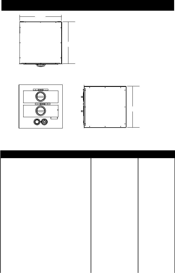
SPECIFICATIONS
Width
Depth
Top View
Height
Front View |
Side View |
IL2088 |
|
MODEL CHART
|
|
|
Individual |
Preheat Times |
|
Dimensions |
Weight |
|||
|
Built-In / |
|
(minutes) |
|
||||||
Model |
Drawers |
Drawer |
|
|
|
|
|
|||
Free Standing |
150°F |
175°F |
“W” |
“D” |
“H” w/o legs |
Installed |
Shipped |
|||
|
|
|
Control |
(65°C) |
(79°C) |
|||||
|
|
|
|
|
|
|
|
|
||
3A81D |
|
1 |
YES |
18.8 |
26.2 |
29 1/16 |
20 3/8 |
11 |
84 lbs |
94 lbs |
3A20D |
|
1 |
YES |
18.8 |
26.2 |
24 1/16 |
22 9/16 |
12 1/4 |
84 lbs |
94 lbs |
3A21D |
|
1 |
YES |
18.8 |
26.2 |
24 1/16 |
22 9/16 |
12 1/4 |
84 lbs |
94 lbs |
3B22D |
|
2 |
NO |
17.2 |
24.8 |
23 1/16 |
24 1/4 |
22 1/8 |
129 lbs |
144 lbs |
3B82D |
Free Standing |
2 |
NO |
18.8 |
26.2 |
29 1/16 |
20 5/16 |
21 1/8 |
120 lbs |
139 lbs |
3B84D |
|
2 |
YES |
18.8 |
26.2 |
29 1/8 |
20 7/16 |
21 5/8 |
120 lbs |
139 lbs |
3C8XD |
|
3 |
NO |
20.6 |
28.2 |
29 1/16 |
20 5/16 |
28 3/4 |
201 lbs |
229 lbs |
3C84D |
|
3 |
YES |
18.8 |
26.2 |
29 1/8 |
20 7/16 |
32 5/16 |
201 lbs |
229 lbs |
3D8XD |
|
4 |
NO |
22.3 |
29.7 |
29 1/16 |
20 5/8 |
36 5/16 |
237 lbs |
252 lbs |
|
|
|
|
|
|
Body Dimensions |
|
|
||
3A20A |
|
1 |
YES |
18.8 |
25.8 |
23 1/16 |
23 |
11 1/4 |
70 lbs |
82 lbs |
3A80A |
|
1 |
YES |
18.8 |
26.2 |
29 1/16 |
19 1/8 |
11 |
72 lbs |
84 lbs |
3B20A |
|
2 |
NO |
17.2 |
21.8 |
23 1/16 |
23 |
22 1/2 |
120 lbs |
138 lbs |
3B80A |
Built-In |
2 |
NO |
18.8 |
26.2 |
29 1/16 |
19 1/4 |
21 1/2 |
125 lbs |
144 lbs |
3B84A |
|
2 |
YES |
18.8 |
26.2 |
29 1/16 |
19 1/4 |
21 3/4 |
125 lbs |
144 lbs |
3C80A |
|
3 |
NO |
20.6 |
28.2 |
29 1/16 |
19 1/4 |
29 5/16 |
171 lbs |
186 lbs |
3C84A |
|
3 |
YES |
18.8 |
26.2 |
29 1/16 |
19 1/4 |
32 1/2 |
206 lbs |
228 lbs |
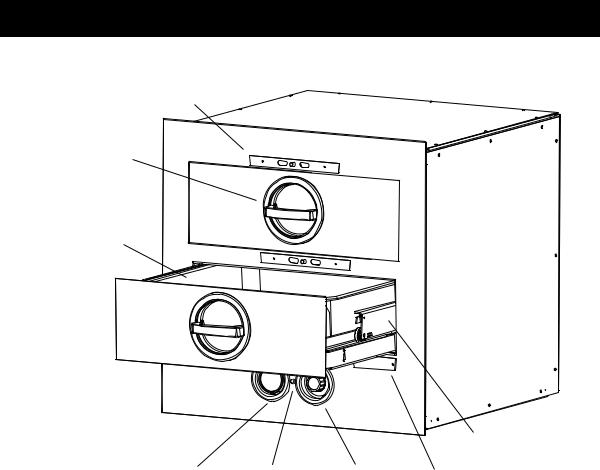
FEATURES & DESCRIPTIONS
COMPONENT LOCATION & FUNCTION
Moisture
Control Adjustment
Handle Latching
Mechanism
Drawer
Pan Insert
Third Member
Drawer Rail
Thermometer Indicator |
Thermostat Knob |
Nameplate |
|
Light |
(Adj 100°F to 200°F) |
IL2089 |
Toastmaster Hot Food Servers are heated drawer-type cabinets designed to HOLD food cooked in advance at serving temperature and proper moisture content.
Thermostat: The thermostat is graduated from 0 to 10 which makes is adjustable from 100°F to 200°F (38°C to 93°C) holding temperature. Some models are equipped with separate thermostat for each drawer. Refer to Specifications on the previous page.
Thermometer: The thermometer is used to visually check if the holding temperature is at the desired setting. Chicken, beef, ribs, fish, potatoes, vegetables and sauces can be held at temperatures with confidence because you can see that the actual holding temperature is safe. The thermometer will tell at a glace if the holding temperature is high enough to retard dangerous bacteria growth and low enough to prevent overcooking and drying out food.
Note: On models with one drawer and on models with individual temperature controls for each drawer the thermostat knob and thermometer are protected with either a wire guard, or the are recessed into the front panel.
Moisture Control: The moisture control consist of a slide which is used to control the amount of moisture allowed to escape form the foods being held.
Indicator Light: The light will illuminate when the unit is calling for heat and will shut off when it has reached the set temperature.
DESCRIPTION continued
|
Accessories |
|
3 & 4 Drawer Free Standing Models: |
7C-3L6 |
Square legs 6” high, stainless steel, set of 4, leveling adj. up to 3/4” |
7C-3L9 |
Square legs 9” high, stainless steel, set of 4, leveling adj. up to 3/4” |
7C-3L12 |
Square legs 12” high, stainless steel, set of 4, leveling adj. up to 3/4” |
7C-3L15 |
Square legs 15” high, stainless steel, set of 4, leveling adj. up to 3/4” |
|
|
7C-3M3 |
Casters, 3”, set of four (swivel without brakes) adds 4-1/4” to unit height |
7C-3M4 |
Casters, 3”, set of four (two swivel/lock, two fixed), adds 4-1/4” to unit height |
|
2 Drawer Free Standing Models: |
7C-3M338STSB |
Casters, 3” set of four swivel (two with brakes), 360lbs. Load capacity |
INSTALLATION
INSTALLATION
A. Inspect for Shipping Damage
All shipping containers should be examined for damage before and during unloading. This equipment was carefully inspected and packaged at the factory. The freight carrier has assumed responsibility for its safe transit and delivery. If equipment is received in damage condition, either apparent of concealed, a claim must be made with the delivery carrier.
1.Apparent Damage or Loss - If damage or loss is apparent it must be noted on the freight bill or express receipt at the time of delivery, and it must be signed by the carrier’s agent (driver). If this is not done, the
carrier may refuse the claim. The carrier will supply the necessary claim forms.
2.Concealed Damage or Loss - If damage or loss is NOT apparent until after equipment is unpacked, a request for inspection of concealed damage must be made with carrier within 15 days. The carrier will make an inspection and will supply necessary claim forms. Be certain to retain all contents plus external and internal packaging materials for inspection.
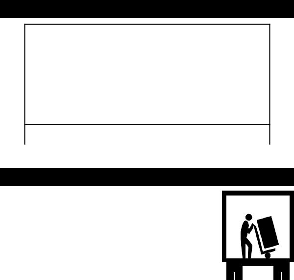
B.Unpacking Hot Food Server
1.Open carton and remove it from around hot food server, then remove the empty carton from the area.
2.Remove all tape from unit and set food server on its side on three 2x4’s (as shown in Figure 2-1) so the packing skid attached to the bottom of the unit is off the ground.
WARNING: DO NOT set the unit on its back, damage could be occur to the power cord or conduit. Place unit on its side.
3. Remove 4 bolts attaching skid to bottom of unit.
INSTALLATION continued
C.Installation of Free-Standing Models
1.Counter top Models 3B22D, 3A81D, 3A20D, 3A21D , 3B82D AND 3B84D.
a.Countertop models are shipped with a set of four 4”(102mm) adjustable legs or an optional set of 4 casters (see Accessories Chart on previous page) can be ordered. Screw the legs or casters into the threaded holes in the corners of the unit bottom.
b.Hot food servers with legs can be set on the floor or on the counter. Units with casters can only be set on the floor. Do not set the hot food server with casters on a counter top.
c.Level unit with legs by turning the hexagonal adjustment feet located at the bottom of the legs.
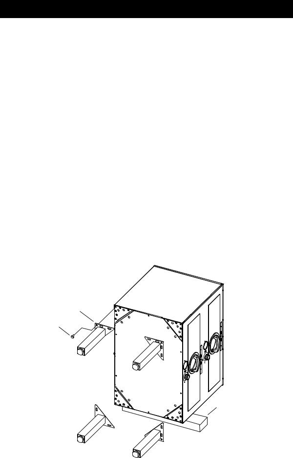
2.Floor Models 3C8XD, 3C84D AND 3D8XD are usually installed as floor models due to their size. One of the available leg or caster accessory kits must be used in the installation.
a.Leg Installation usingaccessorykit(seechartforavailablelegorcasteraccessories, sold separately)
Locate and open the accessory leg kit and the hardware package included with it.
With the hot food server on it side and the 2x4’s still positioned under the unit, align the square corner of a leg flange with a corner of the unit. Attach the leg flange using 5 of the bolts furnished. Refer to figure 2-2.
Repeat for remaining three legs.
Carefully set unit upright, using a level, level the server by turning the adjustable feet.
b.Caster Installation using accessory kit (see chart for available leg or caster accessories, sold separately)
The casters kits are installed the same as the leg kits above, except 2 of the casters are fixed and should be installed at one end or at the rear. The other 2 swivel casters with brakes are installed opposite the fixed casters.
LEG
BOLT
2” x 4”
IL2094
Fig. 2-1, Leg / Caster Installation
INSTALLATION continued
3.Electrical Connections:
FREE STANDING UNITS: All free standing hot food servers are quipped with a factory installed 36” (914mm) cord and plug.
•120V models: Plug conforms to NEMA Standard 5-15P
•208/240V models: Plug conforms to NEMA Standard 6-15P
BUILT-IN UNITS: Most units are provided with a 48” flexible metal conduit for electrical connections (see electrical specifications for specifics).
D. Installation of Built-In Units:
All of these units are true built-in models and are designed to be installed into the front face of a counter fixture. Front of units extends beyond the body to form a self-trimming flange that covers the cut out in the fixture.
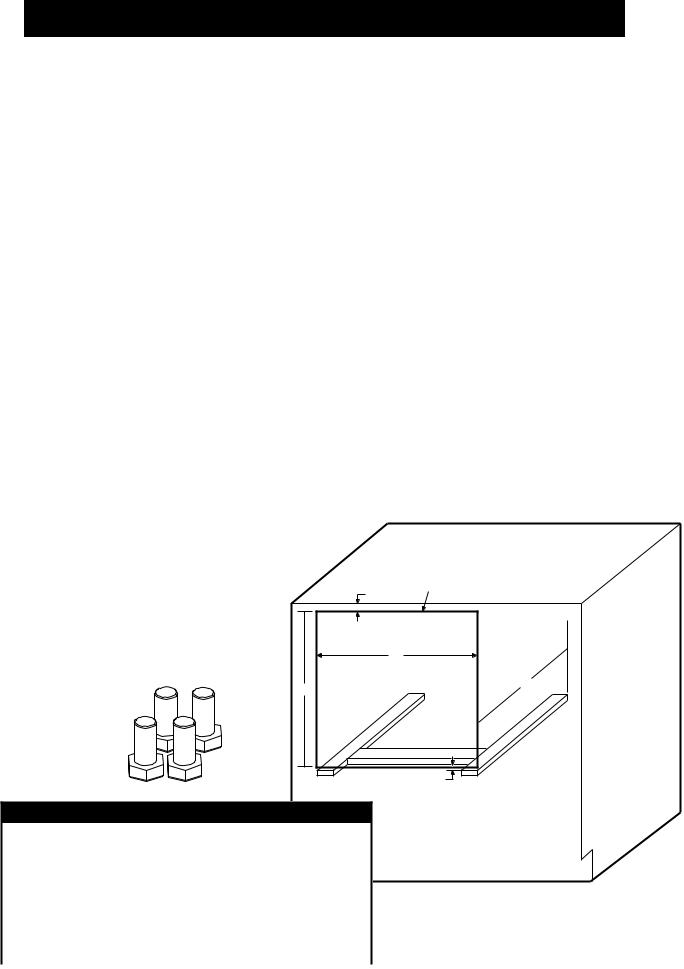
1.Cabinet Cut Out and Support. Cut out the face of the counter fixture according to the drawing that is provided with your hot food server. Figure 2-5 can also be used for the cut out drawing of your model number. As shown in the drawing allow 1/2” (13mm) minimum cabinet face material above top of cut out opening. This allows unobstructed seating of hot food server flange.
Be sure counter fixture has adequate depth from front face to inside of back to accept the hot food server. Minimum depths are shown for each model in Figure 2-5.
a.The hot food server body must be supported from the bottom. This can be accomplished by installing metal support angles of wooden support blocks as shown in Figure 2-5. The supports are not supplied and must be furnished using a suitable strength metal or wood. The top surface of these supports must be 1/16” (3mm) below the bottom edge of the face cut out. A metal or wood crossbrace approximately 2-1/2” (64mm) wide should be securely mounted between the supports as shown. The center line of the crossbrace must be 4” (102mm) from the face of the cut out and its top surface must be flush with the side supports.
b.An alternate support method is to install a solid flat platform in lieu of the side supports and crossbrace. The top surface of the platform must be 1/16” (3mm) below the bottom edge of the cut out.
2.Install Leveling Feet (shown below). Open the top drawer
and remove the small cloth bag Cut Opening for containing four hex head cap Hot Food Server
screws&twomountingscrews. |
1/2” Minimum |
|
|
||
Thread these four screws hand |
|
|
tight up into the four holes in |
|
|
the bottom of the unit. Refer to |
A |
|
2-6. |
||
|
||
B |
C |
|
|
||
Right: Leveling Feet for |
|
|
Built-in Units. |
|
|
(pn: 2C-1513D8805) |
|
|
IL2100 |
|
|
|
1/2” Minimum |
|
BUILT-IN MODELS OPENING DIMENSIONS |
|
Model |
“A” Width |
|
“B” Height |
“C” Depth |
|
|
|
|
|||
3A20A |
23 3/8” |
594 mm |
11 1/2” |
292 mm |
24 1/2” |
622 mm |
|
|
|
||
3B20A |
22 |
3/4” |
578 mm |
|
|
|
|||||
|
|
|
|||||||||
|
|
|
|
|
|
|
|
||||
3A80A |
|
|
11 |
1/4’ |
286 mm |
20 5/8” |
524 mm |
|
Figure 2-5, Cabinet Mounting |
IL2090-01 |
|
3B80A |
29 3/8” |
746 mm |
21 |
3/4” |
552 mm |
|
|
|
|
|
|
|
|
|
|
|
|
||||||
3C80A |
29 |
1/2” |
749 mm |
20 3/4” |
527 mm |
|
|
|
|||
3B84A |
|
|
22” |
559 mm |
|
|
|
||||
|
|
|
|
|
|
|
|
||||
3C84A |
|
|
32 |
3/4” |
832 mm |
|
|
|
|
|
|
INSTALLATION continued
3.Electrical Connection. All electrical connections required for this unit must be performed by a certified electrician. Built-in models are equipped with a 3/4” (19mm) diameter x 4ft. (122cm) long flexible conduit containing power lead pigtails and a ground wire. It is necessary that this conduit and the wiring leads connect at a junction box in accordance with local codes. Be sure to check the data plate on the front of the unit to be sure the power supply is correct. 115V units operate on voltage ranging from 110V to 125V. 220V units operate on voltage ranging from 208V to 240V.
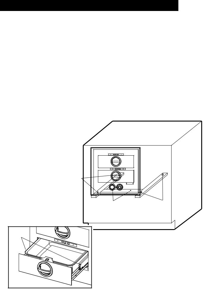
4.Mount Unit in Cabinet.
a.Remove the drawer(s) from the unit, pull the drawer(s) out to the stop. Grasp the entire drawer assembly at the sides as if to lift it and locate your thumbs on the tabs of the drawer slide (figure 2-7). Press down on these tabs with your thumbs and simultaneously pull out on the drawer. Set drawer assembly aside.
b.Lift the unit form both sides and start its backside into the cut out. Push back until the trim flange meets the face of the fixture.
c.Place a level on the floor of the unit and check from side to side and front to back. If adjustments are necessary, slide the entire unit out of the fixture and adjust the leveling feet as required.
d.Secure the unit into position after leveling. There are two holes in the unit bottom for this purpose (See Figure 2-6). Place a drill bit down through these two holes and bore two pilot holes into the crossbrace beneath. Tighten a pair of flat head sheet metal screws down through these holes and into the crossbrace. The unit is now installed.
e.Replace the drawers. NOTE: The drawers of multiple drawer units are individually identified (ex: “TOP”, “2” AND “3”). They should be reinstalled in their respective positions.
E.Initial Start-up
1.Turn on the branch line circuit breaker
2.Set the thermostat control dial at “10” the indiactor light will
come on indicating that unit is calling for heat.
3. After a few minutes have elapsed, open a drawer and check that the unit is heating.
NOTE: If your unit is equipped with |
leveling feet |
|
|
Bolts used as |
|
a separate thermostat for each |
|
|
drawer, complete Steps 2 & 3 |
|
|
for each drawer individually. |
|
|
4. If unit fails to heat, recheck to |
|
|
be sure circuit breakers are |
Drill starter holes and attach |
Bolts used as |
on and electrical connections |
hot food server to support through |
leveling feet |
these two holes. |
|
|
are properly made. If it still |
Use flat head screws. |
|
|
|
|
fails to heat, call a Toastmaster |
|
|
Authorized Service Agent. |
|
|
Drawer |
Release Tabs |
IL2101 |
IL2090-02
Above: Figure 2-6, Cabinet Mounting Left: Figure 2-7, Drawer Release Tabs
 Loading...