


OPERATING INSTRUCTIONS
VOICE EVACUATION SYSTEM
FS-7000 SERIES
Thank you for purchasing TOA's Voice Evacuation System.
Please carefully follow the instructions in this manual to ensure long, trouble-free use of your equipment.
TABLE OF CONTENTS |
|
|
1. |
SAFETY PRECAUTIONS ................................................................................. |
5 |
2. |
SYSTEM SUMMARY ......................................................................................... |
7 |
3. |
FEATURES ........................................................................................................... |
8 |
4. |
HANDLING PRECAUTIONS ........................................................................... |
8 |
5. |
NOMENCLATURE AND FUNCTIONS |
|
|
5.1. FS-7000CP Control Panel ................................................................................. |
9 |
|
5.2. FS-7010CP Expansion Control Panel ............................................................. |
11 |
|
5.3. FS-7000JP Junction Panel .............................................................................. |
11 |
|
5.4. FS-7000PS DC Power Supply Panel .............................................................. |
12 |
|
5.5. FS-7000AT Attenuator Control Panel ............................................................. |
12 |
|
5.6. FS-7000EV Voice Evacuation Panel ............................................................... |
13 |
|
5.7. FS-7000GM Group Matrix Panel ..................................................................... |
14 |
|
5.8. FS-7000RF Remote Microphone Interface Panel ........................................... |
14 |
|
5.9. FS-7000RM Remote Microphone ................................................................... |
15 |
5.10. FS-7010RM Remote Microphone Extension ................................................... |
16 |
|
5.11. FS-7006PA/7012PA Power Amplifiers ............................................................ |
17 |
|
5.12. YA-7000 Amplifier Auto Switching Module ...................................................... |
17 |
|
6.FUNCTIONS & OPERATION OF EMERGENCY/GENERAL-PURPOSE BROADCASTS
6.1. Emergency Broadcasts .................................................................................... |
18 |
6.2. General-Purpose Broadcasts |
|
6.2.1. Types of General-Purpose Broadcasts .................................................. |
18 |
6.2.2. BGM Broadcasts & Priority Broadcasts ................................................. |
19 |
6.2.3. Order of Priority among Priority Broadcasts .......................................... |
20 |
6.2.4. "Normal" Mode and "Urgency" Mode All-Zone Calls .............................. |
20 |
7. MAKING EMERGENCY BROADCASTS |
|
7.1. Initiating Emergency Broadcasts Manually ...................................................... |
21 |
7.2. Initiating Emergency Broadcasts by Fire Alarm System .................................. |
23 |
7.3. Recording Voice Alarm Messages |
|
7.3.1. Recording ............................................................................................... |
25 |
7.3.2. Checking Recorded Content .................................................................. |
26 |
8. MAKING GENERAL-PURPOSE BROADCASTS |
|
8.1. Making General-Purpose Broadcasts from the FS-7000CP ............................ |
27 |
8.2. Making Announcements from the FS-7000RM ................................................ |
28 |
8.3. Making BGM Broadcasts |
|
8.3.1. When using 1-channel broadcasting ...................................................... |
29 |
8.3.2. When using 2-channel broadcasting ...................................................... |
29 |
3
9. FAILURE INDICATION .................................................................................... |
30 |
10. TROUBLESHOOTING .................................................................................... |
31 |
11. SPECIFICATIONS |
|
11.1. FS-7000CP Control Panel ............................................................................. |
32 |
11.2. FS-7010CP Expansion Control Panel ........................................................... |
33 |
11.3. FS-7000JP Junction Panel ............................................................................ |
34 |
11.4. FS-7000PS DC Power Supply Panel ............................................................ |
35 |
11.5. FS-7000AT Attenuator Control Panel ........................................................... |
35 |
11.6. FS-7000EV Voice Evacuation Panel ............................................................. |
36 |
11.7. FS-7000GM Group Matrix Panel ................................................................... |
37 |
11.8. FS-7000RF Remote Microphone Interface Panel ......................................... |
37 |
11.9. FS-7000RM Remote Microphone ................................................................. |
38 |
11.10. FS-7010RM Remote Microphone Extension ................................................. |
38 |
11.11. FS-7006PA/7012PA Power Amplifiers .......................................................... |
39 |
11.12. YA-7000 Amplifier Auto Switching Module .................................................... |
40 |
4

1. SAFETY PRECAUTIONS
•Before installation or use, be sure to carefully read all the instructions in this section for correct and safe operation.
•Be sure to follow all the precautionary instructions in this section, which contain important warnings and/or cautions regarding safety.
•After reading, keep this manual handy for future reference.
Safety Symbol and Message Conventions
Safety symbols and messages described below are used in this manual to prevent bodily injury and property damage which could result from mishandling. Before operating your product, read this manual first and understand the safety symbols and messages so you are thoroughly aware of the potential safety hazards.
 WARNING
  CAUTION
Indicates a potentially hazardous situation which, if mishandled, could result in death or serious personal injury.
Indicates a potentially hazardous situation which, if mishandled, could result in moderate or minor personal injury, and/or property damage.
 WARNING
When Installing the Unit
•FS-7000PS/7006PA/7012PA only
Do not expose the unit to rain or an environment where it may be splashed by water or other liquids, as doing so may result in fire or electric shock.
Use the unit only with the voltage specified on the unit. Using a voltage higher than that which is specified may result in fire or electric shock.
Do not cut, kink, otherwise damage nor modify the power supply cord. In addition, avoid using the power cord in close proximity to heaters, and never place heavy objects -- including the unit itself -- on the power cord, as doing so may result in fire or electric shock.
•FS-7006PA/7012PA, YA-7000 only
Be sure to replace the unit's terminal cover after connection completion. Because the voltage of up to 100 V is applied to the high impedance speaker terminals (FS-7006PA/7012PA, YA-7000) and Main/standby Amplifier terminals (YA-7000), never touch these terminals to avoid electric shock.
•All units
Avoid installing or mounting the unit in unstable locations, such as on a rickety table or a slanted surface. Doing so may result in the unit falling down and causing personal injury and/or property damage.
Install the unit only in a location that can structurally support the weight of the unit and the mounting bracket. Doing otherwise may result in the unit falling down and causing personal injury and/or property damage.
Owing to the unit's size and weight, be sure that at least two persons are available to install the unit. Failure to do so could result in personal injury.
Tighten each nut and bolt securely. Ensure that the bracket has no loose joints after installation to prevent accidents that could result in personal injury.
When the Unit is in Use
•FS-7000PS/7006PA/7012PA only
To prevent a fire or electric shock, never open nor remove the unit case as there are high voltage components inside the unit. Refer all servicing to qualified service personnel.
Do not place cups, bowls, or other containers of liquid or metallic objects on top of the unit. If they accidentally spill into the unit, this may cause a fire or electric shock.
Do not insert nor drop metallic objects or flammable materials in the ventilation slots of the unit's cover, as this may result in fire or electric shock.
Do not touch a plug during thunder and lightning, as this may result in electric shock.
5

 WARNING
When the Unit is in Use
•All units
Should the following irregularity be found during use, immediately switch off the power, disconnect the power supply plug from the AC outlet and contact your nearest TOA dealer. Make no further attempt to operate the unit in this condition as this may cause fire or electric shock.
·If you detect smoke or a strange smell coming from the unit.
·If water or any metallic object gets into the unit
·If the unit falls, or the unit case breaks
·If the power supply cord is damaged (exposure of the core, disconnection, etc.): FS-7000PS/7006PA/7012PA only
·If it is malfunctioning (no tone sounds.)
 CAUTION
When Installing the Unit
•FS-7000PS/7006PA/7012PA only
Never plug in nor remove the power supply plug with wet hands, as doing so may cause electric shock.
When unplugging the power supply cord, be sure to grasp the power supply plug; never pull on the cord itself. Operating the unit with a damaged power supply cord may cause a fire or electric shock.
When moving the unit, be sure to remove its power supply cord from the wall outlet. Moving the unit with the power cord connected to the outlet may cause damage to the power cord, resulting in fire or electric shock. When removing the power cord, be sure to hold its plug to pull.
Do not block the ventilation slots in the unit's cover. Doing so may cause heat to build up inside the unit and result in fire. Also, periodically clean the ventilation slots of dust.
To avoid electric shocks, be sure to switch off the unit's power when connecting speakers.
Be sure to follow the instructions below when rackmounting the unit. Failure to do so may cause a fire or personal injury.
·Install the equipment rack on a stable, hard floor. Fix it with anchor bolts or take other arrangements to prevent it from falling down.
·When connecting the unit's power cord to an AC outlet, use the AC outlet with current capacity allowable to the unit.
•All units
Avoid installing the unit in humid or dusty locations, in locations exposed to the direct sunlight, near the heaters, or in locations generating sooty smoke or steam as doing otherwise may result in fire or electric shock.
When unpacking or moving the unit, be sure to handle it with two or more persons. Falling or dropping the unit may cause personal injury and/or property damage.
When the Unit is in Use
•FS-7006PA/7012PA only
Do not operate the unit for an extended period of time with the sound distorting. This is an indication of a malfunction, which in turn can cause heat to generate and result in a fire.
•FS-7000CP/7006PA/7012PA only
Make sure that the volume control is set to minimum position before power is switched on. Loud noise produced at high volume when power is switched on can impair hearing.
•FS-7000PS/7006PA/7012PA only
If dust accumulates on the power supply plug or in the wall AC outlet, a fire may result. Clean it periodically. In addition, insert the plug in the wall outlet securely.
Switch off the power, and unplug the power supply plug from the AC outlet for safety purposes when cleaning or leaving the unit unused for 10 days or more. Doing otherwise may cause a fire or electric shock.
•All units
Contact your TOA dealer as to the cleaning. If dust is allowed to accumulate in the unit over a long period of time, a fire or damage to the unit may result.
6

2. SYSTEM SUMMARY
The FS-7000 system is a combined emergency/general-purpose broadcasting system.
It is capable of automatically broadcasting the emergency evacuation messages recorded to the FS-7000EV to areas linked to automatic fire alarm systems, as well as manually making emergency broadcasts to specifically selected areas, either via microphone or by pre-recorded announcement.
The FS-7000EV can be recorded with 2 different messages using a connected microphone or audio playback equipment, for example 1 message offering evacuation instructions and the other a false alarm announcement. The combined available recording time for these 2 messages is 3 minutes.
General-purpose broadcasting from the FS-7000CP or FS-7000RM can go to specific individual areas or to multiple areas selected as a group. General all-zone calls can be either "Normal" or "Urgency." Urgency allzone calls are made to all areas and override speaker attenuators to deliver the broadcast at maximum volume.
The installation of a YA-7000 within the power amplifier connected to a standby amplifier allows broadcasts to continue uninterrupted, even in the event that the main power amplifier fails, by automatically switching the broadcast to the standby unit.
Note
For details on setting up and using the various available functions, refer to pages 9 through 17 covering the names and functions of each part or component.
[System Diagram]
Floor identifier signal
Up to 200 zones
Automatic fire alarm system
FS-7000RM
Up to 4 units
Speaker line
Up to 200 zones (Expandable in 10-zone units)
4-wire system control
Attenuator
Telephone paging
PBX
BGM player |
|
Up to 4 units |
230 V AC, 50 Hz |
|
7
3. FEATURES
•The FS-7000EV is loaded with English language messages when shipped from the factory.
•The semiconductor memory incorporated in the FS-7000EV ensures stable rebroadcast of recorded messages.
•If speaker lines are shorted, the line protection fuse disconnects the shorted lines and a line short indication is displayed.
•Simultaneous 2-channel broadcasts can be made of BGM (background music) and announcement broadcasts (emergency and priority broadcasts), allowing BGM broadcasts to continue in zones not selected for announcement broadcasts, even when announcements are being made.
•Up to 4 remote microphones can be connected.
•Up to 200 speaker lines can be controlled.
•Time signals can be simultaneously broadcast over all zones by connecting timer-operated sound sources.
•All-zone calls can be made from a telephone set by connecting the system to a telephone exchange.
•Connection of the emergency power supply panel permits emergency broadcasts to be made even during a power failure.
4. HANDLING PRECAUTIONS
•When moving equipment from one place to another or when installing optional components in an equipment rack, leave all necessary work to your TOA dealer.
•Ensure that the front and rear of the component are sufficiently distant from the wall to facilitate operation and maintenance service.
•When cleaning components, be sure to first switch off the power, then wipe with a dry cloth. If they are very dirty, use a cloth moistened in a neutral cleanser. Never use volatile liquids, such as benzene, thinner or chemically-treated towels, since the component surface is damaged.
8
5. NOMENCLATURE AND FUNCTIONS
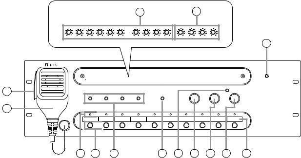
5.1. FS-7000CP Control Panel
The FS-7000CP is a standard operation panel for the FS-7000 Series Voice Evacuation Systems.
It is designed to be used in conjunction with the FS-7000JP panel, and enables individual paging calls to up to 10 zones plus all-zone calls.
The number of zones can be expanded to up to 200 zones in 10-zone units by connecting the FS-7010CP expansion panel. Further, connection of both the FS-7000GM panel and the FS-7010CP panel permits creation of up to 20 broadcast zone groups.
The FS-7000CP is equipped with a built-in pre-amplifier function and chime unit (ascending 4-note tone). Audio output can be set to either a 2-channel output of background music (BGM) and priority broadcast or a 1- channel output of mixed BGM and priority broadcast.
[Front]
Inside of the front cover |
4 |
5 |
1
3 |
2 |
6 |
7 |
8 |
9 |
10 |
11 |
12 |
13 |
14 |
1.Power Indicator
Lights when power is supplied and the FS7000CP is ready for operation.
2.CP Microphone
Make announcements while holding down the Talk Switch (3). The microphone can be used only while the FS-7000CP panel is in use or emergency broadcasts are in progress.
3.Talk Switch
Hold down this switch to make announcements using the microphone.
4.Volume Controls
Adjust the sound volume for each audio input. Turning the control clockwise increases the volume, while turning it counterclockwise decreases the volume.
Controls are arranged from left to right as follows:
• EV
Adjusts the volume of the EV Audio Input on the rear panel.
• TIMER
Adjusts the volume of the Timer Input on the rear panel.
• PAGING
Adjusts the volume of the Paging Input on the rear panel.
• RM MIC
Adjusts the volume of the RF Audio Input on the rear panel.
• CP MIC
Adjusts the volume of the CP Microphone (2).
• CHIME
Adjust the volume of the built-in 4-tone chime.
• BGM 1 – 4
Adjusts the volume of BGM Inputs 1 – 4 on the rear panel.
9
5.Tone Controls
Adjust high and low frequencies of the output. Frequencies are accentuated when the control is rotated clockwise, and attenuated when rotated counterclockwise. Controls are arranged from left to right as follows:
• PRIORITY BASS
Adjusts the low frequencies of the Priority Output on the rear panel.
• PRIORITY TREBLE
Adjusts the high frequencies of the Priority Output on the rear panel.
• BGM BASS
Adjusts the low frequencies of the BGM Output on the rear panel.
• BGM TREBLE
Adjusts the high frequencies of the BGM Output on the rear panel.
6.Zone Indicators
Light to indicate current broadcast zones.
Note
These indicators also light during emergency broadcasts when broadcast zones are selected by signal inputs from an automatic fire alarm system.
7.Zone Selector Keys
Press these keys to select broadcast zones. To cancel the selection, press the keys again. Multiple broadcast zones can be selected simultaneously with the additional use of the FS7000GM panel.
8.Busy Status Indicators
The indicator corresponding to the component currently in use for broadcast lights while the system is in general-purpose broadcast mode.
Note
These indicators do not light during emergency broadcasts.
The priorities of the indicators are: TIMER, PAGING, RM MIC, and CP IN-USE from high to low. (Emergency broadcasts take precedence over all other equipment operations.)
Each indicator is arranged from left to right as follows:
• TIMER
Remains lit during broadcasts from the component connected to the timer input.
• PAGING
Remains lit during broadcasts from the component connected to the paging input.
• RM MIC
Remains lit during broadcasts from the FS7000RM.
• CP IN-USE
Remains lit during broadcasts from the FS7000CP. Announcements can be made via the CP Microphone (2).
9.Speaker Line Short Indicator
Lights when 1 or more speaker lines connected to the FS-7000JP have shorted.
(See page 30.)
10.All-Zone Call Indicator
Lights when the All-Zone Call button (13) is pressed to select all broadcast zones simultaneously. (Lights continuously only while the FS-7000CP is operating or emergency broadcasts are being made.)
11.Chime Button
Sounds a built-in 4-tone chime. This button can be used only while the FS-7000CP is operating.
12.Reset Button
Resets the broadcast zones selected with the Zone Selector keys (7) or All-Zone Call button (13). Pressing this button also terminates general-purpose broadcasts provided from the FS-7000CP.
13.All-Zone Call Button
Selects all broadcast zones simultaneously.
14.Broadcast Zone Fill-In Space
Write the names of zones to be selected with the Zone Selector keys (7) in this space.
10
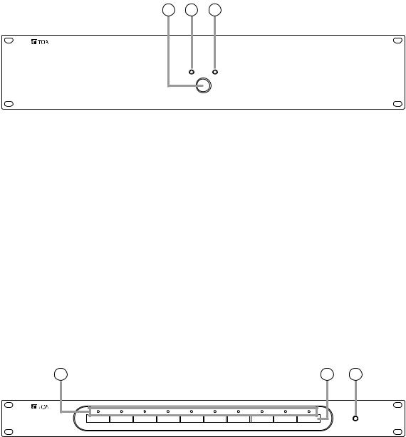
5.2. FS-7010CP Expansion Control Panel
The FS-7010CP is used to expand the broadcasting capacity of FS-7000 Series Voice Evacuation Systems. Announcements and background music can be broadcast to up to 10 individual zones. Connecting the FS7000GM to the FS-7000CP/FS-7010CP combination permits broadcasts to be made to up to 20 zone groups.
[Front]
2 |
3 |
4 |
1 |
1.Power Indicator
Lights when power is supplied and the FS7010CP is ready for operation.
2.Zone Selector Keys
Press these keys to select broadcast zones. To cancel the selection, press the keys again. Multiple broadcast zones can be selected simultaneously with the additional use of the FS7000GM.
3.Zone Indicators
Light to indicate current broadcast zones.
Note
These indicators also light during emergency broadcasts when their corresponding zones are selected by automatic fire alarm signals.
4.Broadcast Zone Fill-In Space
Write the names of zones to be selected with the Zone Selector keys (2) in this space.
5.3. FS-7000JP Junction Panel
The FS-7000JP panel is used in conjunction with the FS-7000CP and the FS-7010CP to connect speaker lines in FS-7000 Series Voice Evacuation Systems. It can connect up to 10 speaker lines. If speaker lines are shorted, the line protection fuses disconnect the shorted lines, leaving broadcasts to other speaker lines functioning intact. The FS-7000JP is equipped with BGM input and priority broadcast input, with BGM broadcast zones selectable using the keys on the front panel. Priority broadcast zones are selected using the FS-7000CP.
[Front]
2 |
3 |
4 |
1 |
1.Power Indicator
Lights when power is supplied and the FS-7000JP panel is ready for operation.
2.BGM Zone Selector Keys
Press these keys to select BGM broadcast zones. Press the keys again to cancel the selection. (2- channel broadcast)
3.Speaker Line Indicators
Indicate speaker line operating statuses as follows:
Green: BGM broadcast in progress (2-channel broadcast)
Orange: BGM broadcast in progress (1-channel broadcast) or priority or emergency broadcasts in progress
Red: Short-circuit (see page 30.)
4.Broadcast Zone Fill-In Space
Write the names of zones to be selected with the BGM Zone Selector keys (2) in this space.
11
5.4. FS-7000PS DC Power Supply Panel
The FS-7000PS supplies 24 V DC power to each component used in FS-7000 Series Voice Evacuation Systems. Connecting the DS-029B provides a power supply for emergency broadcasts even during power failures.
[Front] |
1 2 3 |
1.AC Power Switch
AC power is turned on and off with each press of this switch.
2.AC Power Indicator
Lights when AC power is supplied and the FS7000PS is ready for operation on AC power.
3.DC Power Indicator
Lights when DC power is supplied and the FS7000PS is ready for operation on DC power.
5.5. FS-7000AT Attenuator Control Panel
The FS-7000AT is used in conjunction with FS-7000 Series Voice Evacuation Systems to control 4-wire system attenuators. Up to 10 zones can be attenuator-controlled. When general urgency or emergency broadcasts are made, the FS-7000AT provides 24 V DC power to allow such broadcasts to bypass the attenuators. The output status of each line can be monitored by the indicators on the front panel.
[Front]
2 |
3 |
1 |
1.Power Indicator
Lights when power is supplied and the FS-7000AT is ready for operation.
2.Attenuator Line Indicators
Light when 24 V DC for bypassing the attenuators are being supplied, and extinguish when the overcurrent protection circuit is triggered due to line shorts or other failures, or when the power supply is cut off.
3.Broadcast Zone Fill-In Space
Write the names of the corresponding broadcast zones in this space.
12
 Loading...