


INSTALLATION MANUAL
VOICE EVACUATION SYSTEM
FS-7000 SERIES
Thank you for purchasing TOA's Voice Evacuation System.
Please carefully follow the instructions in this manual to ensure long, trouble-free use of your equipment.
TABLE OF CONTENTS |
|
1. SAFETY PRECAUTIONS ................................................................................. |
5 |
2. SYSTEM SUMMARY ......................................................................................... |
7 |
3. FEATURES ........................................................................................................... |
8 |
4. INSTALLATION PRECAUTIONS ................................................................... |
8 |
5. NOMENCLATURE AND FUNCTIONS |
|
5.1. FS-7000CP Control Panel ................................................................................. |
9 |
5.2. FS-7010CP Expansion Control Panel ............................................................. |
13 |
5.3. FS-7000JP Junction Panel .............................................................................. |
14 |
5.4. FS-7000PS DC Power Supply Panel .............................................................. |
16 |
5.5. FS-7000AT Attenuator Control Panel ............................................................. |
17 |
5.6. FS-7000EV Voice Evacuation Panel ............................................................... |
18 |
5.7. FS-7000GM Group Matrix Panel ..................................................................... |
20 |
5.8. FS-7000RF Remote Microphone Interface Panel ........................................... |
21 |
5.9. FS-7000RM Remote Microphone ................................................................... |
23 |
5.10. FS-7010RM Remote Microphone Extension ................................................... |
25 |
5.11. FS-7006PA/7012PA Power Amplifiers ............................................................ |
26 |
5.12. YA-7000 Amplifier Auto Switching Module ...................................................... |
28 |
6. CONNECTIONS |
|
6.1. Basic System Configuration ............................................................................. |
29 |
6.2. Zone Expansion ............................................................................................... |
31 |
6.3. 24 V DC Power Supply Expansion ................................................................... |
33 |
6.4. Power Amplifier Expansion .............................................................................. |
34 |
6.5. 2-Channel Broadcasts ...................................................................................... |
35 |
6.6. Systems Combining the FS-7000RF, FS-7000RM, and FS-7010RM .............. |
37 |
6.6.1. Connecting the FS-7000RF to 2 FS-7000RMs ...................................... |
40 |
6.6.2. Joining the FS-7000RM to the FS-7010RM ........................................... |
42 |
6.7. FS-7000GM |
|
6.7.1. Changing the FS-7000CP's/7010CP's zone selector keys |
|
into group selector keys ......................................................................... |
43 |
6.7.2. Changing the FS-7000RM's zone selector keys |
|
into group selector keys ......................................................................... |
49 |
6.8. Connecting the FS-7000AT to 4-Wire System Attenuators .............................. |
51 |
6.9. Standby Amplifiers ........................................................................................... |
54 |
6.10. Timer-Operated Equipment .............................................................................. |
56 |
6.11. Telephone Paging ............................................................................................ |
56 |
6.12. BGM Players .................................................................................................... |
57 |
6.13. FS-7000EV ....................................................................................................... |
58 |
6.14. Automatic Fire Alarm Systems ......................................................................... |
59 |
6.15. Power Failure Backup |
|
6.15.1. Providing Backup Power Using |
|
an Uninterruptible Power Supply (UPS) System ................................. |
60 |
6.15.2. Power Backup Using |
|
the DS-029B Emergency Power Supply Panel .................................... |
60 |
3

7. TABLE FOR CABLES |
|
7.1. Cables Supplied with Equipment ..................................................................... |
64 |
7.2. Cables To Be Prepared by the Customers |
|
7.2.1. FS-7000CP Control Panel .................................................................... |
66 |
7.2.2. FS-7010CP Expansion Control Panel ................................................... |
66 |
7.2.3. FS-7000JP Junction Panel ................................................................... |
67 |
7.2.4. FS-7000PS DC Power Supply Panel .................................................... |
67 |
7.2.5. FS-7000AT Attenuator Control Panel ................................................... |
67 |
7.2.6. FS-7000EV Voice Evacuation Panel .................................................... |
68 |
7.2.7. FS-7000GM Group Matrix Panel .......................................................... |
68 |
7.2.8. FS-7000RF Remote Microphone Interface Panel ................................. |
68 |
7.2.9. FS-7000RM Remote Microphone ......................................................... |
68 |
7.2.10. FS-7006PA/7012PA Power Amplifiers .................................................. |
69 |
7.2.11. YA-7000 Amplifier Auto Switching Module ........................................... |
69 |
8. REMOVABLE TERMINAL PLUG CONNECTION .................................. |
70 |
9. PARTS INSTALLATION |
|
9.1. Installing Diodes on the FS-7000GM's Circuit Board ....................................... |
71 |
9.2. Changing the Operation Mode of the FS-7000RM Microphone ....................... |
75 |
10. MOUNTING THE YA-7000 IN THE POWER AMPLIFIER .................... |
76 |
11. FAILURE INDICATION .................................................................................... |
77 |
12. SPECIFICATIONS |
|
12.1. FS-7000CP Control Panel ............................................................................. |
79 |
12.2. FS-7010CP Expansion Control Panel ........................................................... |
80 |
12.3. FS-7000JP Junction Panel ............................................................................ |
81 |
12.4. FS-7000PS DC Power Supply Panel ............................................................ |
82 |
12.5. FS-7000AT Attenuator Control Panel ........................................................... |
82 |
12.6. FS-7000EV Voice Evacuation Panel ............................................................. |
83 |
12.7. FS-7000GM Group Matrix Panel ................................................................... |
84 |
12.8. FS-7000RF Remote Microphone Interface Panel ......................................... |
84 |
12.9. FS-7000RM Remote Microphone ................................................................. |
85 |
12.10. FS-7010RM Remote Microphone Extension ................................................. |
85 |
12.11. FS-7006PA/7012PA Power Amplifiers .......................................................... |
86 |
12.12. YA-7000 Amplifier Auto Switching Module .................................................... |
87 |
SUPPLEMENT |
|
1. SETTINGS TABLE ........................................................................................... |
88 |
2. FS-7000RM/FS-7010RM ZONE IDENTIFICATION CARDS ............... |
91 |
4

1. SAFETY PRECAUTIONS
•Before installation or use, be sure to carefully read all the instructions in this section for correct and safe operation.
•Be sure to follow all the precautionary instructions in this section, which contain important warnings and/or cautions regarding safety.
•After reading, keep this manual handy for future reference.
Safety Symbol and Message Conventions
Safety symbols and messages described below are used in this manual to prevent bodily injury and property damage which could result from mishandling. Before operating your product, read this manual first and understand the safety symbols and messages so you are thoroughly aware of the potential safety hazards.
 WARNING
  CAUTION
Indicates a potentially hazardous situation which, if mishandled, could result in death or serious personal injury.
Indicates a potentially hazardous situation which, if mishandled, could result in moderate or minor personal injury, and/or property damage.
 WARNING
When Installing the Unit
•FS-7000PS/7006PA/7012PA only
Do not expose the unit to rain or an environment where it may be splashed by water or other liquids, as doing so may result in fire or electric shock.
Use the unit only with the voltage specified on the unit. Using a voltage higher than that which is specified may result in fire or electric shock.
Do not cut, kink, otherwise damage nor modify the power supply cord. In addition, avoid using the power cord in close proximity to heaters, and never place heavy objects -- including the unit itself -- on the power cord, as doing so may result in fire or electric shock.
•FS-7006PA/7012PA, YA-7000 only
Be sure to replace the unit's terminal cover after connection completion. Because the voltage of up to 100 V is applied to the high impedance speaker terminals (FS-7006PA/7012PA, YA-7000) and Main/standby Amplifier terminals (YA-7000), never touch these terminals to avoid electric shock.
•All units
Avoid installing or mounting the unit in unstable locations, such as on a rickety table or a slanted surface. Doing so may result in the unit falling down and causing personal injury and/or property damage.
Install the unit only in a location that can structurally support the weight of the unit and the mounting bracket. Doing otherwise may result in the unit falling down and causing personal injury and/or property damage.
Owing to the unit's size and weight, be sure that at least two persons are available to install the unit. Failure to do so could result in personal injury.
Tighten each nut and bolt securely. Ensure that the bracket has no loose joints after installation to prevent accidents that could result in personal injury.
When the Unit is in Use
•FS-7000PS/7006PA/7012PA only
To prevent a fire or electric shock, never open nor remove the unit case as there are high voltage components inside the unit. Refer all servicing to qualified service personnel.
Do not place cups, bowls, or other containers of liquid or metallic objects on top of the unit. If they accidentally spill into the unit, this may cause a fire or electric shock.
Do not insert nor drop metallic objects or flammable materials in the ventilation slots of the unit's cover, as this may result in fire or electric shock.
Do not touch a plug during thunder and lightning, as this may result in electric shock.
5

 WARNING
When the Unit is in Use
•All units
Should the following irregularity be found during use, immediately switch off the power, disconnect the power supply plug from the AC outlet and contact your nearest TOA dealer. Make no further attempt to operate the unit in this condition as this may cause fire or electric shock.
·If you detect smoke or a strange smell coming from the unit.
·If water or any metallic object gets into the unit
·If the unit falls, or the unit case breaks
·If the power supply cord is damaged (exposure of the core, disconnection, etc.): FS-7000PS/7006PA/7012PA only
·If it is malfunctioning (no tone sounds.)
 CAUTION
When Installing the Unit
•FS-7000PS/7006PA/7012PA only
Never plug in nor remove the power supply plug with wet hands, as doing so may cause electric shock.
When unplugging the power supply cord, be sure to grasp the power supply plug; never pull on the cord itself. Operating the unit with a damaged power supply cord may cause a fire or electric shock.
When moving the unit, be sure to remove its power supply cord from the wall outlet. Moving the unit with the power cord connected to the outlet may cause damage to the power cord, resulting in fire or electric shock. When removing the power cord, be sure to hold its plug to pull.
Do not block the ventilation slots in the unit's cover. Doing so may cause heat to build up inside the unit and result in fire. Also, periodically clean the ventilation slots of dust.
To avoid electric shocks, be sure to switch off the unit's power when connecting speakers.
Be sure to follow the instructions below when rackmounting the unit. Failure to do so may cause a fire or personal injury.
·Install the equipment rack on a stable, hard floor. Fix it with anchor bolts or take other arrangements to prevent it from falling down.
·When connecting the unit's power cord to an AC outlet, use the AC outlet with current capacity allowable to the unit.
•All units
Avoid installing the unit in humid or dusty locations, in locations exposed to the direct sunlight, near the heaters, or in locations generating sooty smoke or steam as doing otherwise may result in fire or electric shock.
When unpacking or moving the unit, be sure to handle it with two or more persons. Falling or dropping the unit may cause personal injury and/or property damage.
When the Unit is in Use
•FS-7006PA/7012PA only
Do not operate the unit for an extended period of time with the sound distorting. This is an indication of a malfunction, which in turn can cause heat to generate and result in a fire.
•FS-7000CP/7006PA/7012PA only
Make sure that the volume control is set to minimum position before power is switched on. Loud noise produced at high volume when power is switched on can impair hearing.
•FS-7000PS/7006PA/7012PA only
If dust accumulates on the power supply plug or in the wall AC outlet, a fire may result. Clean it periodically. In addition, insert the plug in the wall outlet securely.
Switch off the power, and unplug the power supply plug from the AC outlet for safety purposes when cleaning or leaving the unit unused for 10 days or more. Doing otherwise may cause a fire or electric shock.
•All units
Contact your TOA dealer as to the cleaning. If dust is allowed to accumulate in the unit over a long period of time, a fire or damage to the unit may result.
6
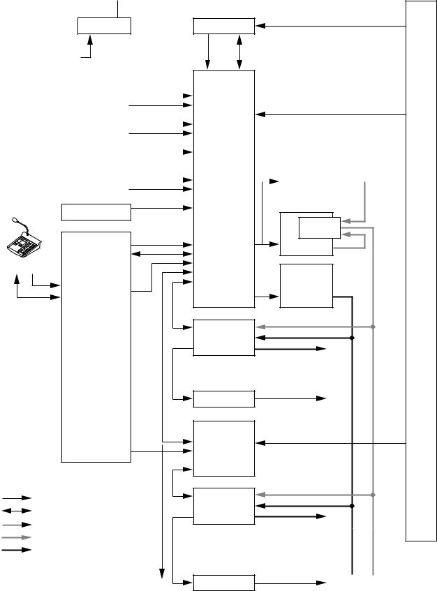
2. SYSTEM SUMMARY
 24 V DC (supplied to rack internal components)
Confirmation signal
FS-7000PS 
 FS-7000EV
230 V AC
50 Hz
|
|
EV IN |
Cont |
|||||
|
|
|
|
|
|
|
|
|
Timer-operated |
|
TIMER |
|
|
|
|
|
|
|
|
|
|
|
|
|
||
sound source |
|
BUSY |
|
|
|
Floor identifier signals 1 – 10 |
||
|
|
FLOOR ID |
||||||
|
|
|||||||
|
|
CP MIC |
|
|
|
|
|
|
CP microphone |
|
|
|
|
|
|
|
|
|
TALK SW |
|
|
|
|
|
|
|
|
|
|
|
|
|
|
|
|
|
|
AUX |
|
|
|
|
|
|
Sound source |
|
|
|
|
|
|
|
|
|
|
|
|
|
|
|
|
|
|
|
CALL |
|
|
|
FS-7006PA |
|
|
|
|
|
|
|
|
|
||
PBX |
|
|
|
|
|
|
||
|
BUSY |
|
|
|
|
|
|
|
|
|
|
|
|
|
|
|
|
|
|
|
|
|
|
|
|
|
BGM player |
BGM |
|
|
|
|
|
|
|
FS-7000CP |
YA-7000 |
|
OUT |
RF IN |
PRIO |
FS-7006PA |
RF CONT |
RF CONT |
|
|
FS-7000RM |
RF ZONE |
|
|
|
CP CONT |
|
|
|
JP CONT |
|
FS-7006PA |
ZONES 1 – 10 |
|
|
|
|
BGM |
|
|
|
|
|
|
FS-7000RF |
FS-7000JP |
|
|
|
|
|
|
Max. 50 zones |
AT CONT |
|
|
|
|
Speaker outputs 1 – 10 |
|
|
|
|
|
|
|
|
Attenuator controls |
|
FS-7000AT |
1 – 10 |
|
|
|
||
|
FS-7010CP |
Floor identifier signals |
|
|
11 – 20 |
||
|
CP CONT |
|
|
|
|
|
|
ZONES 11 – 20 |
RF CONT |
|
|
|
GM CONT |
|
|
|
JP CONT |
|
|
: Control line, 1-way |
FS-7000JP |
|
|
: Control line, 2-way |
AT CONT |
|
|
: Audio signal |
|
|
|
|
|
Speaker outputs |
|
: Speaker output (priority) |
|
|
|
|
|
11 – 20 |
|
: Speaker output (BGM) |
|
|
|
Attenuator controls
11 – 20
FS-7000AT
Automatic fire alarm system
7

3. FEATURES
•The FS-7000EV is loaded with English language messages when shipped from the factory.
•The semiconductor memory incorporated in the FS-7000EV ensures stable rebroadcast of recorded messages.
•If speaker lines are shorted, the line protection fuse disconnects the shorted lines and a line short indication is displayed.
•Simultaneous 2-channel broadcasts can be made of BGM (background music) and announcement broadcasts (emergency and priority broadcasts), allowing BGM broadcasts to continue in zones not selected for announcement broadcasts, even when announcements are being made.
•Up to 4 remote microphones can be connected.
•Up to 200 speaker lines can be controlled.
•Time signals can be simultaneously broadcast over all zones by connecting timer-operated sound sources.
•All-zone calls can be made from a telephone set by connecting the system to a telephone exchange.
•Connection of the emergency power supply panel permits emergency broadcasts to be made even during a power failure.
4. INSTALLATION PRECAUTIONS
•The required power voltage for this system is 230V AC. Calculate the total combined power consumption of all equipment in the system to ensure ample power capacity. Note that the system may not work properly due to breaker cutoff or power voltage drops when the total supply voltage is insufficient.
•About the handling of the power supply cord (FS-7000PS only):
The supplied power cord is intended for exclusive use with the FS-7000PS Power Supply Panel. Avoid using this power cord for any other equipment than the PS-7000PS panel.
•Ensure that the rear of the component is sufficiently distant from the rear wall to facilitate maintenance service. Speaker line protection fuses and output overcurrent fuses are located on the component rear panel. Sufficient space must be provided between the back of the component and the rear wall surface to change the fuses.
•When mounting the FS-7000PS and FS-7006PA or FS-7012PA in an equipment rack, mount a Perforated Panel larger than 1U size* just above and below each component, as shown in the following figure.
Perforated Panels |
DC Power Supply Panel |
|
FS-7000PS |
Perforated Panels |
Power Amplifiers |
|
FS-7006PA/7012PA |
•When mounting the FS-7006PA or FS-7012PA power amplifier in an equipment rack, keep the rear of the amplifier at least 10 cm away from the rear wall so that its rear panel-mounted fan vent is not blocked.
•Each component is designed with robust construction. However, be sure to use reinforcement brackets when mounting if extra strength is required.
•No rack mounting screws are supplied with the system. Use the appropriate screws for the racks used.
*1U size = 44.5 mm (standard size)
8

5. NOMENCLATURE AND FUNCTIONS
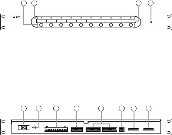
5.1. FS-7000CP Control Panel
The FS-7000CP is a standard operation panel for the FS-7000 Series Voice Evacuation Systems.
It is designed to be used in conjunction with the FS-7000JP panel, and enables individual paging calls to up to 10 zones plus all-zone calls.
The number of zones can be expanded to up to 200 zones in 10-zone units by connecting the FS-7010CP expansion panel. Further, connection of both the FS-7000GM panel and the FS-7010CP panel permits creation of up to 20 broadcast zone groups.
The FS-7000CP is equipped with a built-in pre-amplifier function and chime unit (ascending 4-note tone). Audio output can be set to either a 2-channel output of background music (BGM) and priority broadcast or a 1- channel output of mixed BGM and priority broadcast.
[Front]
Inside of the front cover |
4 |
5 |
1
3 |
2 |
6 |
7 |
8 |
9 |
10 |
11 |
12 |
13 |
14 |
1.Power Indicator
Lights when power is supplied and the FS7000CP is ready for operation.
2.CP Microphone
Make announcements while holding down the Talk Switch (3). The microphone can be used only while the FS-7000CP panel is in use or emergency broadcasts are in progress.
3.Talk Switch
Hold down this switch to make announcements using the microphone.
4.Volume Controls
Adjust the sound volume for each audio input. Turning the control clockwise increases the volume, while turning it counterclockwise decreases the volume.
Controls are arranged from left to right as follows:
• EV
Adjusts the volume of the EV Audio Input on the rear panel.
• TIMER
Adjusts the volume of the Timer Input on the rear panel.
• PAGING
Adjusts the volume of the Paging Input on the rear panel.
• RM MIC
Adjusts the volume of the RF Audio Input on the rear panel.
• CP MIC
Adjusts the volume of the CP Microphone (2).
• CHIME
Adjust the volume of the built-in 4-tone chime.
• BGM 1 – 4
Adjusts the volume of BGM Inputs 1 – 4 on the rear panel.
9
5.Tone Controls
Adjust high and low frequencies of the output. Frequencies are accentuated when the control is rotated clockwise, and attenuated when rotated counterclockwise. Controls are arranged from left to right as follows:
• PRIORITY BASS
Adjusts the low frequencies of the Priority Output on the rear panel.
• PRIORITY TREBLE
Adjusts the high frequencies of the Priority Output on the rear panel.
• BGM BASS
Adjusts the low frequencies of the BGM Output on the rear panel.
• BGM TREBLE
Adjusts the high frequencies of the BGM Output on the rear panel.
6.Zone Indicators
Light to indicate current broadcast zones.
Note
These indicators also light during emergency broadcasts when broadcast zones are selected by signal inputs from an automatic fire alarm system.
7.Zone Selector Keys
Press these keys to select broadcast zones. To cancel the selection, press the keys again. Multiple broadcast zones can be selected simultaneously with the additional use of the FS7000GM panel.
8.Busy Status Indicators
The indicator corresponding to the component currently in use for broadcast lights while the system is in general-purpose broadcast mode.
Note
These indicators do not light during emergency broadcasts.
The priorities of the indicators are: TIMER, PAGING, RM MIC, and CP IN-USE from high to low. (Emergency broadcasts take precedence over all other equipment operations.)
Each indicator is arranged from left to right as follows:
• TIMER
Remains lit during broadcasts from the component connected to the timer input.
• PAGING
Remains lit during broadcasts from the component connected to the paging input.
• RM MIC
Remains lit during broadcasts from the FS7000RM.
• CP IN-USE
Remains lit during broadcasts from the FS7000CP. Announcements can be made via the CP Microphone (2).
9.Speaker Line Short Indicator
Lights when 1 or more speaker lines connected to the FS-7000JP have shorted.
(See page 77.)
10.All-Zone Call Indicator
Lights when the All-Zone Call button (13) is pressed to select all broadcast zones simultaneously. (Lights continuously only while the FS-7000CP is operating or emergency broadcasts are being made.)
11.Chime Button
Sounds a built-in 4-tone chime. This button can be used only while the FS-7000CP is operating.
12.Reset Button
Resets the broadcast zones selected with the Zone Selector keys (7) or All-Zone Call button (13). Pressing this button also terminates general-purpose broadcasts provided from the FS-7000CP.
13.All-Zone Call Button
Selects all broadcast zones simultaneously.
14.Broadcast Zone Fill-In Space
Write the names of zones to be selected with the Zone Selector keys (7) in this space.
10
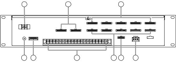
[Rear] |
|
|
|
|
|
|
|
|
|
|
|
15 |
16 |
17 18 |
19 |
20 |
21 |
22 |
23 |
24 |
25 |
26 |
27 |
28 |
29 |
30 |
31 |
32 |
33 |
34 |
35 |
36 |
37 |
38 |
15.DC Power Input Terminal
Connect 24 V DC power to this terminal. Power is supplied from the FS-7000PS.
(M3 screw terminal; barrier distance: 6.4 mm)
16.BGM Input Terminals 2,3,4
Connect background music equipment to these terminals. When the output is set to 2-channel broadcast, background music is supplied from the BGM Output (30). When the output is set to 1-channel broadcast, background music is mixed with priority broadcasts and provided from the Priority Output (31) as well. However, activation of the muting function* due to signal inputs other than BGM will attenuate the BGM level.
BGM inputs 2 – 4: –20 dBV, 10 kΩ, unbalanced, 2P RCA jack
* Muting function: A function that automatically decreases the volume of original broadcast when another broadcast is initiated during original broadcast, and restores the original broadcast volume level when the other broadcast is completed.
17.Mute Switch
Sets whether or not to attenuate the signal levels of BGM Inputs 2 – 4 (16) when a broadcast is made from the BGM Input 1 (18). (Default: OFF)
18.BGM Input Terminal 1
Connect background music equipment to this terminal. When the output is set to 2-channel broadcast, BGM is supplied from the BGM Output (30). Setting the muting function permits this input to take precedence over BGM Inputs 2
– 4. When the output is set to 1-channel broadcast, background music is mixed with priority broadcasts and provided from the Priority Output (31) as well. However, activation of the muting function due to signal inputs other than BGM will attenuate the BGM level. (–60 dBV/0 dBV selectable, 600 Ω, balanced, 3P terminal block)
19.BGM Input 1 Sensitivity Selector Switch
Sets the input sensitivity of BGM Input 1 (18) to "–60 dBV" or "0 dBV." (Default: 0 dBV)
20.Paging Input Terminal
Connect audio and control signals from equipment (such as telephone paging equipment) to this terminal. Input signals to this terminal are broadcast when the control terminals are closed.
Audio: –60 dBV/–20 dBV selectable, 600 Ω, balanced
Control: Open voltage: 26 V DC; short-circuit current: under 2 mA
5P terminal block
21.Paging Input Sensitivity Selector Switch
Sets the input sensitivity of Paging Input (20) to "–60 dBV" or "–20 dBV."
(Default: –20 dBV)
22.RF Audio Input Terminal
Used to connect the FS-7000RF. Audio signals from the FS-7000RM are input via the FS7000RF. (0 dBV, 600 Ω, balanced, 3P terminal block)
23.Auxiliary Input Terminal
Signals received by this terminal are mixed with signals from the CP Microphone (2) and output while the FS-7000CP is in operation.
(–20 dBV, 600 Ω, unbalanced, 2P terminal block)
24.Auxiliary Input Volume Control
Adjusts the sound volume of Auxiliary Input (23).
11
25.Timer Input Terminal
Connect audio and control signals from timeroperated equipment to this terminal. Input signals to this terminal are broadcast with the highest priority when the control terminals are closed.
Audio: 0 dBV, 600 Ω, unbalanced
Control: Open voltage: 26 V DC; short-circuit current: under 2 mA
4P terminal block
26.EV Audio Input Terminal
Used to connect the FS-7000EV. This input can be used only while an emergency broadcast is being made. (0 dBV, 600 Ω, unbalanced, 2P terminal block)
27.Output Mode Selector Switch
Sets the audio output to "1-CH" (1-channel) or "2-CH" (2-channel) broadcasts.
(Default: 2-channel broadcast)
28.Functional Earth Terminal
Connect this terminal to the functional earth terminal of external equipment if excessive noise is generated when the FS-7000CP is connected to the external equipment. This could reduce noise.
Note: This terminal is not for protective earth.
29.All-Zone Call Mode Selector Switch
Sets the mode of broadcast to be initiated with the All-Zone Call button (13). When the FS7000AT has been connected to the system, if this switch is set to "URGE" (general urgency) and an all-zone call is made, a 24 V DC for controlling attenuators is output, permitting the call to bypass the attenuator. (Default: "NORM")
30.BGM Output Terminal
Signals from the BGM Inputs 1 – 4 (16 and 18) are mixed and output. Connect this terminal to the power amplifier for BGM broadcast. (0 dBV, 600 Ω, balanced, 3P terminal block)
31.Priority Output Terminal
When the Output Mode Selector Switch (27) is set to 2-channel broadcast:
Outputs signals other than those from the BGM Inputs 1 – 4 (16 and 18). Connect this terminal to the power amplifier intended for priority broadcast.
When the Output Mode Selector Switch (27) is set to 1-channel broadcast:
Outputs signals from all audio inputs. Signals output from sources other than BGM Inputs 1 – 4 causes these 4 BGM input signals to atttenuate. Connect this terminal to the power amplifier. (0 dBV, 600 Ω, balanced, 3P terminal block)
32.Automatic Fire Alarm System Input Terminal
Connect this terminal to the floor identifier signal transmitted from the automatic fire alarm system. The identifier signal automatically selects zones and broadcasts audio alarms to such zones. (Open voltage: 26 V DC; short-circuit current: under 5 mA; 12P terminal block; 10 zones + COM + COM)
Note
This terminal is not connected when the FS7000EV is not used.
33.EV Control Terminal
Connect the FS-7000EV to this terminal.
34.RF Zone Control Terminal
Use this terminal to connect the FS-7000RF. Data regarding broadcast zones transmitted from the FS-7000RF is input to this terminal.
35.RF Control Terminal
Use this terminal to connect the FS-7000RF.
36.CP Control Terminal
Use this terminal to connect the FS-7010CP. All of the FS-7010CP units that are mounted in the system must be connected to this terminal.
37.JP Control Terminal
Connect this terminal to the FS-7000JP when the FS-7000GM is not connected to the system.
Note
This terminal is not used when the FS-7000GM is connected to the FS-7000CP.
38.JP/GM Control Terminal
Connect this terminal to the FS-7000JP or FS7000GM.
When the FS-7000GM is not connected to the FS-7000CP:
Connect this terminal to the FS-7000JP in order to control speaker line ON/OFF operations.
When the FS-7000GM is connected to the FS7000CP:
Connect this terminal to the FS-7000GM. The Zone Selector keys (7) on the front panel function as group selector keys.
12
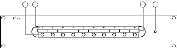
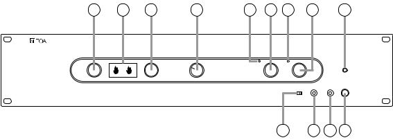
5.2. FS-7010CP Expansion Control Panel
The FS-7010CP is used to expand the broadcasting capacity of FS-7000 Series Voice Evacuation Systems. Announcements and background music can be broadcast to up to 10 individual zones. Connecting the FS7000GM to the FS-7000CP/FS-7010CP combination permits broadcasts to be made to up to 20 zone groups.
[Front]
2 |
3 |
4 |
1 |
1.Power Indicator
Lights when power is supplied and the FS7010CP is ready for operation.
2.Zone Selector Keys
Press these keys to select broadcast zones. To cancel the selection, press the keys again. Multiple broadcast zones can be selected simultaneously with the additional use of the FS7000GM.
3.Zone Indicators
Light to indicate current broadcast zones.
Note
These indicators also light during emergency broadcasts when their corresponding zones are selected by automatic fire alarm signals.
4.Broadcast Zone Fill-In Space
Write the names of zones to be selected with the Zone Selector keys (2) in this space.
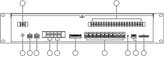
[Rear]
5 |
6 |
7 |
8 |
9 |
10 |
11 |
12 |
5.DC Power Input Terminal
Connect 24 V DC power to this terminal. Power is supplied from the FS-7000PS.
(M3 screw terminal; barrier distance: 6.4 mm)
6.Functional Earth Terminal
Connect this terminal to the functional earth terminal of external equipment if excessive noise is generated when the external equipment is connected to the FS-7010CP. This could reduce noise.
Note: This terminal is not for protective earth.
7.Automatic Fire Alarm System Input Terminal
Connect this terminal to floor identifier signals transmitted from the automatic fire alarm system. The identifier signal designates broadcast zones to provide audio alarm to such zones. (Open voltage: 26 V DC; short-circuit current: under 5 mA; 12P terminal block; 10 zones + COM + COM)
Note: This terminal is not connected when the FS7000EV is not used.
8.RF Zone Control Terminal
Use this terminal to connect the FS-7000RF.
9.CP Control Terminal
Connect this terminal to the FS-7000CP or other FS-7010CP units. All of the FS-7010CP units within the system must be connected to the FS7000CP.
10.JP Control Terminal
Connect this terminal to the FS-7000JP Junction Panel.
11.JP Zone Control Terminal
Connect this terminal to the FS-7000JP in order to control speaker line ON/OFF operations.
12.GM Zone Control Terminal
Connect this terminal to the FS-7000GM when the FS-7000GM is connected to the FS-7000CP.
13
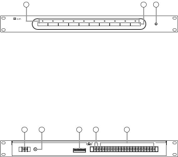
5.3. FS-7000JP Junction Panel
The FS-7000JP panel is used in conjunction with the FS-7000CP and the FS-7010CP to connect speaker lines in FS-7000 Series Voice Evacuation Systems. It can connect up to 10 speaker lines. If speaker lines are shorted, the line protection fuses disconnect the shorted lines, leaving broadcasts to other speaker lines functioning intact. The FS-7000JP is equipped with BGM input and priority broadcast input, with BGM broadcast zones selectable using the keys on the front panel. Priority broadcast zones are selected using the FS-7000CP.
[Front]
2 |
3 |
4 |
1 |
1.Power Indicator
Lights when power is supplied and the FS-7000JP panel is ready for operation.
2.BGM Zone Selector Keys
Press these keys to select BGM broadcast zones. Press the keys again to cancel the selection. (2- channel broadcast)
3.Speaker Line Indicators
Indicate speaker line operating statuses as follows:
Green: BGM broadcast in progress (2-channel broadcast)
Orange: BGM broadcast in progress (1-channel broadcast) or priority or emergency broadcasts in progress
Red: Short-circuit (see page 77.)
4.Broadcast Zone Fill-In Space
Write the names of zones to be selected with the BGM Zone Selector keys (2) in this space.
14
[Rear]
5 |
6 |
7 |
8 |
9 |
10 |
11 |
12 |
13 |
14 |
15 |
16 |
5.DC Power Input Terminal
Connect 24 V DC power to this terminal. Power is supplied from the FS-7000PS.
(M3 screw terminal; barrier distance: 6.4 mm)
6.Speaker Output Terminal
Connect this terminal to speaker lines. Ten lines can be connected.
Maximum per-line output (high impedance, 100 V line)
When the FS-7006PA amplifier is connected: 280 W
When the FS-7012PA amplifier is connected: 500 W
(M3 screw terminal; barrier distance: 6.4 mm)
7.Functional Earth Terminal
Connect this terminal to the functional earth terminal of external equipment if excessive noise is generated when the FS-7000JP panel is connected to the external equipment. This could reduce noise.
Note: This terminal is not for protective earth.
8.General Urgency/Emergency Mode Output Terminal
Activated while a General urgency broadcast or Emergency broadcast is being made.
(Open collector output; rated voltage: 30 V DC; current capacity: 0.1 A; 2P terminal block)
9.Power Remote Output Terminal
Activated when a broadcast is made to any zone. This terminal can be used for remotely controlling the power amplifier's power supply.
(Relay output; rated voltage: 30 V DC; current capacity: 1 A; 2P terminal block)
10.BGM Input Terminal
Connect this terminal to the power amplifier intended for BGM broadcast.
(M4 screw terminal; barrier distance: 9 mm)
Note
Only 1 piece of FS-7006PA, FS-7012PA or YA7000 can be connected to this terminal. Never connect 2 or more units to this terminal, as the excessive load could cause the amplifier to fail.
11.Priority Input Terminal
Connect this terminal to the output of the power amplifier intended for priority broadcast.
(M4 screw terminal; barrier distance: 9 mm)
Note
Only 1 piece of FS-7006PA, FS-7012PA or YA7000 can be connected to this terminal. Never connect 2 or more units to this terminal, as the excessive load could cause the amplifier to fail.
12.Attenuator Connection Terminal
Connect this terminal to the FS-7000AT.
13.Speaker Line Protection Fuses
Disconnect shorted speaker lines to prevent adverse effects on other speaker lines.
Note
Install the fuse having the correct capacity for all the connected speakers.
14.Reset Switch
Pressing this switch after removing the cause of a speaker line short and replacing the blown Speaker Line Protection Fuse (13) restores broadcasts to that speaker line.
15.JP Control Terminal
Connect this terminal to the FS-7000CP and FS7010CP.
16.JP Zone Control Terminal
Connect this terminal to the FS-7000CP and FS7010CP to select speaker lines during priority broadcasts.
15
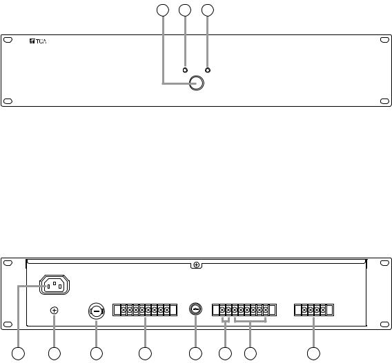
5.4. FS-7000PS DC Power Supply Panel
The FS-7000PS supplies 24 V DC power to each component used in FS-7000 Series Voice Evacuation Systems. Connecting the DS-029B provides a power supply for emergency broadcasts even during power failures.
[Front] |
1 2 3 |
1.AC Power Switch
AC power is turned on and off with each press of this switch.
2.AC Power Indicator
Lights when AC power is supplied and the FS7000PS is ready for operation on AC power.
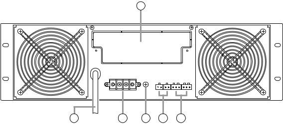
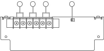
[Rear]
3.DC Power Indicator
Lights when DC power is supplied and the FS7000PS is ready for operation on DC power.
4 |
5 |
6 |
7 |
8 |
9 |
10 |
11 |
4.AC Power Inlet
Connect the supplied power cord to this inlet.
5.Functional Earth Terminal
Connect this terminal to the functional earth terminal of external equipment if excessive noise is generated when the external equipment is connected to the FS-7000PS. This could reduce noise.
Note: This terminal is not for protective earth.
6.AC Fuse
Protects the unit against output overcurrent when the unit is operated on AC power. When replacing the fuse, use the specified type.
7.24 V DC Output Terminal
Connect this terminal to the 24 V DC input of each system component.
M3 screw terminal; barrier distance: 6.4 mm; current capacity: 5 A (total).
8.DC Fuse
Protects the unit against output overcurrent when the unit is operated on DC power. When replacing the fuse, use the specified type.
9.Grounding Terminal
Disconnects a 24 V DC output ground from a frame ground. (Default: Shorted between F.G and S.G)
(M3 screw terminal; barrier distance: 6.4 mm)
10.Emergency Power Connection Terminal
Connect this terminal to the DS-029B to enable emergency broadcasts even during power failures.
(M3 screw terminal; barrier distance: 6.4 mm)
11.Emergency Power Control Terminal
Activates an emergency power supply unit to enable emergency broadcasts during power failures. Connect this terminal to the FS-7000EV. (M3 screw terminal; barrier distance: 6.4 mm)
16
5.5. FS-7000AT Attenuator Control Panel
The FS-7000AT is used in conjunction with FS-7000 Series Voice Evacuation Systems to control 4-wire system attenuators. Up to 10 zones can be attenuator-controlled. When general urgency or emergency broadcasts are made, the FS-7000AT provides 24 V DC power to allow such broadcasts to bypass the attenuators. The output status of each line can be monitored by the indicators on the front panel.
[Front]
2 |
3 |
1 |
1.Power Indicator
Lights when power is supplied and the FS-7000AT is ready for operation.
2.Attenuator Line Indicators
Light when 24 V DC for bypassing the attenuators are being supplied, and extinguish when the overcurrent protection circuit is triggered due to line shorts or other failures, or when the power supply is cut off.
3.Broadcast Zone Fill-In Space
Write the names of the corresponding broadcast zones in this space.
[Rear]
4 |
5 |
6 |
7 |
8 |
4.DC Power Input Terminal
Connect this terminal to 24 V DC power to be used for internal circuits. Power is supplied from the FS-7000PS.
(M3 screw terminal; barrier distance: 6.4 mm)
5.Functional Earth Terminal
Connect this terminal to the functional earth terminal of external equipment if excessive noise is generated when the external equipment is connected to the FS-7000AT. This could reduce noise.
Note: This terminal is not for protective earth.
6.AT Control Terminal
Connect this terminal to the FS-7000JP to control ON/OFF operations of the Attenuator Control Output (8).
7.ATT DC Power Input Terminal
Connect this terminal to 24 V DC power used for attenuator control to be output from the Attenuator Control Output Terminals 1 – 10 (8).
(M3 screw terminal; barrier distance: 6.4 mm)
8.ATT Control Output Terminals
Provide 24 V DC output for bypassing the attenuators during general urgency or emergency broadcasts.
[M3 screw terminal; barrier distance: 6.4 mm; maximum current capacity: 5 A (total of 10 lines)/0.75 A (per line)]
17
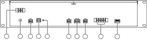
5.6. FS-7000EV Voice Evacuation Panel
The FS-7000EV is an emergency broadcast operation panel for FS-7000 Series Voice Evacuation Systems. This panel is not required if the system is to be used solely for general-purpose public address applications. It is possible to start and reset emergency broadcasts through manual operation. The FS-7000EV has a built-in voice alarm device that can make both evacuation and false-alarm announcements. Not only are evacuation announcements automatically broadcast when the system receives a fire instruction signal from the connected automatic fire alarm system, they can also be initiated using the Evacuation Announcement button on the front panel. False alarm announcements can be initiated using the False Alarm Announcement button on the front panel. Evacuation and false alarm announcement messages can also be recorded using the appropriate buttons on the front of the panel, in which case the recorded message can be confirmed by listening with headphones.
[Front] |
2 |
3 |
4 |
5 |
6 |
7 |
8 |
9 |
1 |
1.Power Indicator
Lights when power is supplied and the FS7000EV is ready for operation.
2.Emergency Reset Button
When it is confirmed that a fire has been extinguished or other emergency situations have returned to normal, press this button to terminate emergency broadcasts after resetting the connected automatic fire alarm system.
3.Fire Indicator
Indicates that an emergency broadcast is in progress. This indicator lights when a fire detection signal is transmitted from the automatic fire alarm system or when the Emergency Activation button (4) is pressed.
4.Emergency Activation Button
Press this button to manually initiate emergency broadcasts after the occurrence of fire has been confirmed.
5.Mode Selector Switch
Selects the operation mode of the FS-7000EV unit to be used as a sound source for evacuation and false alarm announcements. Set the mode to "NORMAL" in general use. No voice alarm is output when the mode is set to "MONITOR" or "RECORD."
Functions of the 3 switch positions are as follows:
NORMAL: Select this mode in general use. Voice alarms are provided at the time of emergency broadcast.
MONITOR: Allows the operator to listen to messages recorded on a sound source.
10 11 12 13
RECORD: Records evacuation and false alarm announcements on a sound source.
(Default: NORMAL)
6.Evacuation Announcement Indicator
Lights or flashes when an evacuation announcement is played back or recorded.
7.Evacuation Announcement Button
Press this button to play back or record evacuation announcements.
8.False Alarm Announcement Indicator
Lights or flashes when a false alarm announcement is played back or recorded.
9.False Alarm Announcement Button
Press this button to play back or record false alarm announcements.
10.Input Sensitivity Setting Switch
Sets the input sensitivity of Recording Input (11). Select the sensitivity depending on the type of connected component.
(Default: –20 dBV)
11.Recording Input Terminal
Used for recording voice alarm messages.
(–60 dBV/2.2 kΩ or –20 dBV/10 kΩ selectable, unbalanced, mini-jack)
12.Headphone Terminal
Connect headphones to this terminal to listen to recorded messages for confirmation. Recorded contents are output regardless of the settings of the Mode Selector switch.
(0 dBV, 100 Ω, unbalanced, mini-jack)
13.Headphone Volume Control
Adjusts the volume of headphones.
18
[Rear]
14 |
15 |
16 |
17 |
18 |
19 |
20 |
21 |
22 |
23 |
14.DC Power Input Terminal
Connect this terminal to 24 V DC power. Power is supplied from the FS-7000PS Power Supply Panel.
(M3 screw terminal; barrier distance: 6.4 mm)
15.Functional Earth Terminal
Connect this terminal to the functional earth terminal of external equipment if excessive noise is generated when the external equipment is connected to the FS-7000EV. This could reduce noise.
Note: This terminal is not for protective earth.
16.EV Audio Output Terminal
Connect this terminal to the FS-7000CP for broadcasting evacuation announcements and other voice alarms. Such alarms are output only when the Mode Selector switch (5) is set to the Normal position.
(0 dBV, 600 Ω, unbalanced, 2P terminal block)
17.USB Terminal
Connect this terminal to a PC or other equipment using the USB cable. With this connection the built-in sound source can be rewritten using dedicated software.
18.USB Communication Indicator
Lights or flashes during USB communications.
19.Emergency ON Output Terminal
Activated during emergency broadcasts. This terminal is connected to the FS-7006PA or FS7012PA amplifier to disable PA attenuators while emergency announcements are being made.
(Relay output; rated voltage: 30 V DC; current capacity: 1 A; 2P terminal block)
20.Emergency Control Contact Output Terminal
There are an output that is activated and an output that is deactivated during emergency announcements.
(Relay output; rated voltage: 30 V DC; current capacity: 1 A; 3P terminal block)
21.Automatic Fire Alarm System Confirmation Signal Input Terminal
Connect this terminal to a confirmation signal (fire confirmation signal) from the automatic fire alarm system. Evacuation announcements are broadcast if they have not yet been initiated when this signal is received.
[Open voltage: 24 V DC; short-circuit current: 6 mA, 2P terminal block (1 channel + COM)]
22.Emergency Power Control Terminal
Activates an emergency power supply unit connected to the FS-7000PS in order to enable emergency broadcasts during power failures. Connect this terminal to the FS-7000PS.
Control input: Rated voltage: 24 V DC; current capacity: 100 mA
Starting output: Open collector output; rated voltage: 30 V DC; current capacity: 100 mA
(M3 screw terminal; barrier distance: 6.4 mm)
23.EV Control Terminal
Connect this terminal to the FS-7000CP Control Panel.
19

5.7. FS-7000GM Group Matrix Panel
The FS-7000GM panel is used in conjunction with FS-7000 Series Voice Evacuation Systems to make group broadcasts. The FS-7000GM connects to the FS-7000CP and FS-7000RF and enables group broadcasts by selecting multiple speaker lines simultaneously via the zone selector keys on the FS-7000CP or FS-7000RM. Up to 20 groups and 50 speaker lines can be made available per unit, which can be expanded to 20 groups and 200 speaker lines by connecting 4 units.
[Front]
1
[Rear]
2 |
3 |
4 |
5 |
6 |
1.Power Indicator
Lights when power is supplied and the FS7000GM is ready for operation.
2.DC Power Input Terminal
Connect this terminal to 24 V DC power supply. Power is supplied from the FS-7000PS.
(M3 screw terminal; barrier distance: 6.4 mm)
3.Functional Earth Terminal
Connect this terminal to the functional earth terminal of external equipment if excessive noise is generated when the external equipment is connected to the FS-7000GM. This could reduce noise.
Note: This terminal is not for protective earth.
4.GM Group Control Output Terminals
Used to increase the number of broadcast zones that can be selected with a single group key by connecting multiple FS-7000GM units. Connect these terminals to other FS-7000GM unit.
5.GM Group Control Input Terminals
Use these terminals to change the zone selector keys on the FS-7000CP into group selector keys by connecting the FS-7000CP. These terminals are also used to enable zone group selection from the FS-7000RM by connecting the FS-7000RF. To increase the number of zones that can be selected simultaneously, connect these terminals to other FS-7000GM's GM Group Control Output Terminals (4).
6.GM Zone Control Terminals
Connect these terminals to the FS-7010CP and FS-7000RF.
20
5.8. FS-7000RF Remote Microphone Interface Panel
The FS-7000RF is used to connect the FS-7000RM to FS-7000 Series Voice Evacuation Systems. Up to 4 FS-7000RM units can be connected using the FS-7000RF. It is possible to control 50 speaker lines as well as all-zone calls. Connection of the FS-7000GM enables broadcasts to be made to up to 20 zone groups.
[Front]
2 |
1 |
1.Power Indicator
Lights when power is supplied and the FS7000RF is ready for operation.
2.Fault Indicator
Lights if any failure is detected in communications with the FS-7000RM and flashes if any failure occurs on the FS-7000RF itself. (See page 77.)
21
[Rear]
3 |
4 |
5 |
6 |
7 |
8 |
3.DC Power Input Terminal
Connect this terminal to 24 V DC power supply. Power is supplied from the FS-7000PS.
(M3 screw terminal; barrier distance: 6.4 mm)
4.GM Group Control Terminals
Connect these terminals to the FS-7000GM. Output is provided when zones are selected using the FS-7000RM's zone selector keys programmed to function as group selector keys.
5.GM Zone Control Terminals
Connect these terminals to the FS-7000GM. Broadcast zones included in the group selected via the FS-7000RM's keys designated as group selector keys are individually input by the FS7000GM.
6.Functional Earth Terminal
Connect this terminal to the functional earth terminal of external equipment if excessive noise is generated when the external equipment is connected to the FS-7000RF. This could reduce noise.
Note: This terminal is not for protective earth.
7.Function Switch
This switch performs the following settings:
• FS-7000RM all-zone call mode (SW #1)
Sets the mode of broadcast selected with the FS7000RM's all-zone call key to Normal or Urgency.
• Number of FS-7000RM units (SW #2 and #3) Sets the number of FS-7000RM units to 1 through 4.
9 10 11
•Number of system's broadcast zones (SW #4~#6)
Sets the number of zones to 10 through 50 in 10zone units.
•Priorities among FS-7000RM units (SW #7 and #8)
Sets priorities among the FS-7000RM units to "None," "Last-In-First-Out," "First-In-First-Out," or "Individual."
(Default: "Normal," "1," "10 zones," and "Last-In- First-Out")
8.FS-7000RM Link Terminals
The following terminals are available for connection of the FS-7000RM:
•AUDIO
Connects the audio line from the FS-7000RM.
• DC 24 V
Supplies 24 V DC power to the FS-7000RM.
• BUS
Communicates data with the FS-7000RM. (M3.5 screw terminal; barrier distance: 7.2 mm)
9.RF Zone Control Terminals
Connect these terminals to the FS-7000CP and/or FS-7010CP. Data of zones selected via the FS-7000RM is output from these terminals.
10.RF Control Terminal
Connect this terminal to the FS-7000CP
11.RF Audio Output Terminal
Connect this terminal to the FS-7000CP. Audio signals from the FS-7000RM are output.
22

5.9. FS-7000RM Remote Microphone
The FS-7000RM Remote Microphone is used solely for general-purpose public address applications in FS7000 Series Voice Evacuation Systems. It enables broadcasting to up to 10 individual zones, as well as allzone calls. One FS-7000RF panel is required in order to connect the FS-7000RM to the system. Up to 4 FS7000RM units can be connected. Pressing the FS-7000RM's chime key causes the FS-7000CP's built-in 4- tone chime to sound. Connection of 4 FS-7010RMs enables broadcasts to 50 individual zones as well as allzone calls (expandable by 10 lines per FS-7010RM). Further, up to 20 broadcast zone groups can be created by connecting the FS-7000RF to an FS-7000GM Group Matrix Panel.
Tip
Connection of 6 FS-7010RM Remote Microphone Extension units enables broadcasting to 50 individual zones and 20 zone groups, as well as all-zone calls.
[Top]
|
1 |
|
2 |
13 |
3 |
4 |
5
6
7
8
1.Power Indicator
Lights when power is supplied and the FS-7000RM is ready for operation.
2.Fault Indicator
Lights when any failure is detected in communications with the FS-7000RF or when any failure occurs on the FS-7000RM itself.
(See page 77.)
3.All-Zone Call Indicator
Remains lit while an all-zone call is broadcast from the FS-7000RM. (Lights only when calls are made from this FS-7000RM.)
4.All-Zone Call Key
Selects all broadcast zones simultaneously.
5.Chime Key
Sounds a 4-tone chime built inside the FS7000CP.
6.Broadcast Reset Key
Resets broadcast zones selected via the All-Zone Call key (4) or Zone Selector keys (11), terminating broadcasts from the FS-7000RM.
7.Busy Indicator
Lights green when a broadcast is made from this FS-7000RM, and lights orange when a broadcast is made from other equipment.
8.Talk Key Indicator
Lights when a microphone announcement is made using the Talk key (12).
9 10
11
12
9.Zone Identification Card
Write the names of the broadcast zones on this card and insert it into the card receptacle from top.
Note
Since this card is not supplied with the FS7000RM, prepare it according to the instructions given on page 91.
10.Zone Selection Indicators
Light when the corresponding Zone Selector keys (11) are pressed. (Light only when the FS7000RM's keys are used.)
11.Zone Selector Keys
Select broadcast zones. Connection of the FS7000RF to the FS-7000GM permits simultaneous selection of multiple broadcast zones.
12.Talk Key
Microphone announcements can be made only while this key is pressed.
Tip
Key operation can be changed to allow microphone announcements to alternate between ON and OFF each time this key is pressed. (See page 75.)
13.Microphone
23
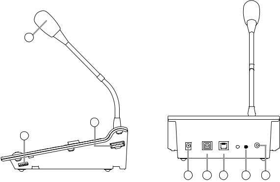
[Right Side] |
[Rear] |
13
15
14
16 17 18 19 20
14.Setting Switch
Performs the following settings:
•Data communications address (0 – 3)
•Number of group keys (0, 10, or 20)
•Microphone compressor (ON/OFF)
[Default settings]
Data communications address: 0
Number of group keys: |
0 |
Microphone compressor: |
ON |
15.FS-7010RM Connection Terminal
Connect the FS-7010RM to this terminal to increase the number of zone selector keys.
16.DC Power Supply Input Terminal
Connect this terminal to an AC adapter.
17.USB Terminal
Not used.
18.FS-7000RF Link Terminal
Connect this terminal to the FS-7000RF.
19.Microphone Volume Control
Adjusts the volume of the Microphone (13) and External Microphone (20).
20.External Microphone Input
Connect this terminal to an external microphone. (–40 dBV, 2.2 kΩ, unbalanced, mini-jack, w/phantom power supply)
24
5.10. FS-7010RM Remote Microphone Extension
The FS-7010RM is an extension unit for the FS-7000RM to be used in FS-7000 Series Voice Evacuation Systems. Ten zones can be expanded per FS-7010RM. Up to 6 FS-7010RM units can be connected to the FS-7000RM.
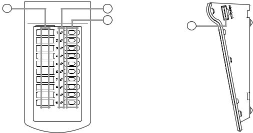
[Top] |
[Right Side] |
1 |
2 |
|
3 |
|
4 |
1.Zone Identification Card
Write the names of the broadcast zones on this card and insert them it the card receptacle from top.
Note
Since this card is not supplied with the FS7010RM, prepare it according to the instructions given on page 91.
2.Zone Selection Indicators
Light when the corresponding Zone Selector keys
(3)are pressed. (Only when zones are selected from the FS-7010RM.)
3.Zone Selector Keys
Select broadcast zones.
4.RM Connection Terminals (located on both sides)
Connect these terminals to the FS-7000RM and/or FS-7010RM.
25
5.11. FS-7006PA/7012PA Power Amplifiers
These power amplifiers are used in conjunction with FS-7000 Series Voice Evacuation Systems. The FS7006PA's output is rated at 600 W and the FS-7012PA is rated to deliver 1,200 W. By mounting the YA-7000 module in a power amplifier and connecting a standby amplifier to it, the power amplifier can be automatically switched over to the standby amplifier if the power amplifier fails. When initiating emergency broadcasts, the volume control on the front panel is bypassed by closing the Volume Bypass Control terminals on the rear panel, allowing broadcasts of emergency message at maximum volume.
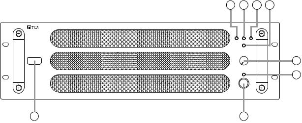
[Front]
Figure shows the FS-7012PA.
5 |
6 |
7 |
8 |
|
3 |
|
2 |
4 |
1 |
1.Power Switch
Press this switch to turn on the power. To turn off the power, press this switch again.
2.Power Indicator
Lights when power is supplied and the FS7006PA/7012PA is ready for operation.
3.Volume Control
Adjusts the input signal level. This volume control cannot be used while the Bypass Indicator (8) continuously lights.
4.Fill-In Space
Write uses of the main and standby amplifiers in this space.
5.Fault Indicator
Lights when an output muting function* is operated or when a failure is detected.
If the YA-7000 is used, this indicator lights when the YA-7000 detects a failure and the power amplifier is switched over to a standby amplifier. (See page 77.)
*This function prevents noise from being generated when power is switched on and off.
6. Signal Indicator
Lights when a signal that exceeds a level 24 dB below the rated output is sent to the Speaker Output (11) on the rear panel.
7. Peak Indicator
Lights when a signal that exceeds a level of 3 dB below the rated output is sent to Speaker Output (11) on the rear panel.
8. Bypass Indicator
Lights when the Volume Bypass Control Input (13) on the rear panel is enabled and indicates that the Volume Control (3) has been bypassed and disabled.
26
[Rear]
Figure shows the FS-7012PA.
9
10 |
11 |
12 |
13 |
14 |
9.YA-7000 Receptacle
Mount an optional YA-7000 module from this receptacle. (See page 76.)
Note
Use of the YA-7000 permits the main amplifier to be switched over to a standby amplifier if the main amplifier fails.
10.Power Cord
Connect this cord to the wall AC outlet (230 V AC, 50 Hz).
11.Speaker Output Terminal (with cover)
This high-impedance, 100 V line output is connected to the FS-7000JP.
Note
Connect this terminal to the YA-7000 when the YA-7000 has been mounted.
• FS-7006PA
M4 screw terminal; barrier distance: 9 mm; load impedance: 16.7 Ω
• FS-7012PA
M4 screw terminal; barrier distance: 9 mm; load impedance: 8.3 Ω
Note
Never connect this terminal to the speaker output terminal of other FS-7006PA or FS-7012PA power amplifier. Failure to follow this instruction could lead to equipment failures.
12.Functional Earth Terminal
Connect this terminal to the functional earth terminal of external equipment if excessive noise is generated when the power amplifier is connected to the external equipment. This could reduce noise.
Note: This terminal is not for protective earth.
13.Volume Control Bypass Control Input Terminal
Bypasses Volume Control (3) on the front panel and allows announcements to be made at maximum volume.
(Open voltage: under 24 V DC; short-circuit current: under 10 mA; 2P terminal block)
14.Audio Signal Input Terminal
Connect this terminal to the FS-7000CP's Priority Output and BGM Output.
(0 dB, 10 kΩ, balanced, 3P terminal block)
27
5.12. YA-7000 Amplifier Auto Switching Module
The YA-7000 module is designed to be mounted in the power amplifier of FS-7000 Series Voice Evacuation Systems. Connecting a standby amplifier to the YA-7000 module installed in the main amplifier (FS-7006PA or FS-7012PA) permits the main amplifier to be switched over to the standby amplifier if the main amplifier fails.
[Front]
1 |
2 |
3 |
4 |
1.Speaker Output Terminal (with cover)
This high-impedance, 100V line speaker output terminal connects to the FS-7000JP. Signals from the Main Amplifier Input (2) are output when the main amplifier (i.e. power amplifier in which the YA-7000 has been mounted) is operating correctly, and signals from the Standby Amplifier Input (3) are output if a main amplifier failure is detected.
(M4 screw terminal; barrier distance: 9 mm)
Note
Never connect this terminal to the speaker output terminal of the FS-7006PA or FS-7012PA power amplifier. Failure to follow this instruction could lead to power amplifier failures.
2.Main Amplifier Input Terminal (with cover)
Connect the main amplifier's speaker output to this terminal.
(M4 screw terminal; barrier distance: 9 mm)
Note
Only 1 piece of FS-7006PA or FS-7012PA can be connected to this terminal. Never connect 2 or more units to this terminal, as the excessive load could cause the amplifier to fail.
3.Standby Amplifier Input Terminal (with cover)
Connect this terminal to the standby amplifier's speaker output.
(M4 screw terminal; barrier distance: 9 mm)
Note
Only 1 piece of the FS-7006PA or FS-7012PA can be connected to this terminal. Never connect 2 or more units to this terminal, as the excessive load could cause the amplifier to fail.
4.Operation Mode Selector Switch
Selects the YA-7000's operation mode. Set this switch to the Normal position in general use. (Default: Normal)
28
 Loading...