


Timberk SWH FSM5 30 V, SWH FSM6 100 H, SWH FSM3 30 V, SWH FSM3 50 V, SWH FSM3 80 V User Manual [ru]
...Instruction manual Руководство по эксплуатации
|
|
Электрический |
Electrical |
|
|
накопительный |
storage water |
|
|
водонагреватель |
heater |
|
|
|
|
|
|
Модели/Models: |
SWH FSM5 30 V |
|
|
|
SWH FSM5 50 V |
|
|
|
SWH FSM5 80 V |
|
|
|
SWH FSM5 100 V |
|
FSM6 |
|
|
|
|
|
SWH FSM6 30 H |
|
|
|
SWH FSM6 50 H |
FSM5 |
|
|
SWH FSM6 80 H |
|
|
|
SWH FSM6 100 H |
|
|
|
SWH FSM3 30 V |
|
|
|
SWH FSM3 50 V |
|
|
|
SWH FSM3 80 V |
|
|
|
SWH FSM3 100 V |
|
|
|
SWH FSM4 30 H |
|
|
|
SWH FSM4 50 H |
|
|
|
SWH FSM4 80 H |
|
FSM4 |
SWH FSM4 100 H |
|
|
|
||
|
|
Outlook of devices, aslo colour scores can be revised without any special advance |
|
|
|
notices. |
|
FSM3 |
|
Производитель вправе менять внешний вид прибора и цветовую гамму при- |
|
|
|
бора без специального уведомления. |
|

TABLE OF CONTENTS
1.Important information
2.Precautions
3.Application of water heater
4.Performance parameters Technical characteristics Dimensional features
5.Water heater description
6.Delivery set
7.Water heater installation Location
Water heater mounting methods Water heater mounting Connection to water main Connection to electric mains
Ground Fault Circuit Interrupter(GFCI)
8.Water heater control Control panel
Water heater operation
9.Maintenance
10.Troubleshooting and error codes
11.Transportation and storage conditions
12.Wiring diagram
13.Disposal
14.Serial number and production date
Dear customer!
Thank you for your good choice. You purchased TIMBERK
2electric storage water heater with an stainless steel internal
3tank. It will serve you for a long time!
3 |
TIMBERK electric storage water heaters will provide a lot |
3of hot water and will automatically maintain the specified
4temperature. They are perfect to provide hot water for country houses, cottages, baths and other standalone amenity rooms.
5
5 |
|
|
6 |
|
|
1. IMPORTANT INFORMATION |
||
7 |
||
|
7
7Please, read this operation manual carefully prior to use of the water heater.
8This operation manual contains important information regarding your safety, as well as recommendations on the proper operation of the unit and
9its maintenance.
9Save this operation manual together with the guarantee card, cash register
10receipt, if possible, cardboard box and packing material.
11Different types of this device are described in this manual.
11 |
The purchased water heater can slightly differ from the one, described in |
||
11 |
the manual, but that doesn’t affect methods of its use and operation. |
||
|
|
|
|
12 |
|
|
|
|
|
IMPORTANT! |
|
13 |
|
|
|
|
|
||
13 |
|
|
Important precautions and instructions, contained in |
14 |
|
|
this manual, do not account for all possible modes and |
|
|
||
|
|
||
14 |
|
|
situations to be encountered. It is vital to understand |
|
|
||
|
|
that common sense, caution and thoroughness are the |
|
14 |
|
|
|
|
|
factors that are impossible to be built-in in any product. |
|
|
|
|
These factors must be taken into consideration by |
|
|
|
a person, interested in proper operation of the unit. |
|
|
|
The manufacturer does not bear any responsibility in |
|
|
|
case when the unit or its parts are damaged during |
|
|
|
transportation, as a result of improper installation, |
|
|
|
voltage fluctuations, as well as if some part of the unit |
|
|
|
was altered or modified. |
|
|
|
|
2. PRECAUTIONS
A number of precautions is to be observed upon operation of the fan heater. Improper operation as a result of ignoring precautions may harm health of the user and other people, as well as damage their property.
1.Any electrical appliance must be supervised when in operation, especially if there are children nearby. Make sure children do not touch the appliance.
2.Prior to installing the water heater, not connecting it to electrical main, check and make sure the outlet for the water heater has a ground pin and if it is properly earthed. If there is no earth circuit in your electrical main then operation of the water heater is dangerous for your life.
3.Connect the water heater only to 220-230V, 50Hz main. If necessary, find out parameters of your mains at power suppliers.
4.To prevent overheating and risk of fire, as well as damage of internal electrical main, do no modify the power cord’s length and do no connect the water heater through electrical extenders.
5.It is forbidden to switch on the water heater if it is not filled with water or if water cannot go through a pressure safety valve.
6.Never use the water heater if it is broken.
7.Do not remove the water heater cover when it is in operation.
8.Immediately unplug the water heater from electrical main if strange sounds, odor or smoke are coming from it.
9.Always unplug the water heater from electrical main during a thunderstorm.
10.Prior to cleaning and maintenance of the water heater unplug it from electrical main. Cleaning and maintenance must be performed in compliance with instructions of this operation manual.
11.Do not use hazardous chemical substances to clean the water heater and prevent their contact with the appliance.
12.To prevent electrical shock the damaged power cord must be replaced only in manufacturer’s authorized service centers by qualified specialists.
13.To prevent electrical shock do not place the power cord nearby heating devices and flammables or combustibles.
14.Do not press buttons on the control panel of the water heater and its remote controller (for some models) otherwise but by your fingers.
15.Since temperature of water in the water heater can reach +75°C, when it is in operation you should not place your body parts under hot water at
the first run.
To prevent burns you should adjust the temperature of the discharging water.
16.Do not use the water heater for purposes not specified by this operation manual.
17.Do not use the water heater in an explosive or corrosive environment. Do not store gas and other volatile flammable liquids next to the appliance
– it is very dangerous!
18.It is forbidden to make alterations in the design of the water heater or modify it.
19.Any service operations must be performed by a specialized organisation and qualified specialists. Improper installation may cause voiding of guarantee maintenance.
20.The water heater is not intended for use by children and persons with reduced physical, sensory or mental capabilities, or a lack of experience and knowledge, unless they have been given supervision or instruction concerning use of the appliance by an individual responsible for their safety. Children should be supervised to ensure that they do not play with the appliance.
3. APPLICATION OF WATER HEATER
Electric water heater is used to heat cold water from water supply. Unit is for household use.
4.PERFORMANCE PARAMETERS
1.Completely automatic control: automatic water heating, continuous automatic water temperature control.
2.DROP Defense – leakage protection and protection against surplus pressure within a tank (pressure safety valve).
HOT Defense – two-stage overheating protection (thermostat and temperature limiter).
ALL PROTECTION SYSTEMS ARE RELIABLE AND SAFE.
3.Pipes of heating elements are designed taking into account high heat load: safe and reliable, with an increased service life.
4.NON CFC urethane foam insulation of increased thickness: excellent heat
2 |
www.timberk.com • electrical storage water heater |
|
www.timberk.com • electrical storage water heater |
3 |
|
|
|
|
|
insulation that allows to efficiently retain accumulated heat and save energy.
5.Temperature controller: accurate and reliable water temperature control.
6.Internal tanks and all internal components are made out of SUS 304 stainless steel with walls 1.2 mm thick.
7.The water heater is equipped with an anode bar to protect the internal tank from corrosion and decrease scale generation on the heating element.
Technical characteristics
Technical characteristics of water heaters are given below in Table 1, 2. Table 1
Description |
Units |
SWH FSM5 30 V/ |
SWH FSM5 50 V/ |
SWH FSM5 80 V/ |
SWH FSM5 100 V/ |
|
SWH FSM6 30 H |
SWH FSM6 50 H |
SWH FSM6 80 H |
SWH FSM6 100 H |
|||
|
|
|||||
Rated voltage |
V/Hz |
~220-230/50 |
~220-230/50 |
~220-230/50 |
~220-230/50 |
|
|
|
|
|
|
|
|
Rated current |
A |
8.7 |
8.7 |
8.7 |
8.7 |
|
|
|
|
|
|
|
|
Rated power |
W |
2000 |
2000 |
2000 |
2000 |
|
|
|
|
|
|
|
|
Stage power |
W |
800/1200/2000 |
800/1200/2000 |
800/1200/2000 |
800/1200/2000 |
|
|
|
|
|
|
|
|
Tank capacity |
L |
30 |
50 |
80 |
100 |
|
|
|
|
|
|
|
|
Rated |
Mpa |
0,7 |
0,7 |
0,7 |
0,7 |
|
pressure |
||||||
|
|
|
|
|
||
|
|
|
|
|
|
|
Water |
|
|
|
|
|
|
protection |
– |
IPX4 |
IPX4 |
IPX4 |
IPX4 |
|
class |
|
|
|
|
|
|
Heating time, |
min |
28 |
46 |
73 |
80 |
|
at 30 ºC |
||||||
|
|
|
|
|
||
|
|
|
|
|
|
|
Appliance |
mm |
550x435x238 |
855x435x238 |
991x493x270 |
1190x493x270 |
|
dimensions |
||||||
|
|
|
|
|
||
|
|
|
|
|
|
|
Weight |
kg |
9,8 |
13,4 |
18,9 |
23,4 |
|
|
|
|
|
|
|
Description |
Units |
SWH FSM5 30 V/ |
SWH FSM5 50 V/ |
SWH FSM5 80 V/ |
SWH FSM5 100 V/ |
|
SWH FSM6 30 H |
SWH FSM6 50 H |
SWH FSM6 80 H |
SWH FSM6 100 H |
|||
|
|
|||||
Factual year |
|
|
|
|
|
|
energy |
kW•h |
335,8 |
452,6 |
481,8 |
518,3 |
|
consumption |
|
|
|
|
|
|
Constant daily |
kW•h / |
0,98 |
1,23 |
1,33 |
1,45 |
|
heating loss |
day |
|||||
|
|
|
|
|||
|
|
|
|
|
|
Table 2
Description |
Units |
SWH FSM3 30 V/ |
SWH FSM3 50 V/ |
SWH FSM3 80 V/ |
SWH FSM3 100 V/ |
|
SWH FSM4 30 H |
SWH FSM4 50 H |
SWH FSM4 80 H |
SWH FSM4 100 H |
|||
|
|
|||||
Rated voltage |
V/Hz |
~220-230/50 |
~220-230/50 |
~220-230/50 |
~220-230/50 |
|
|
|
|
|
|
|
|
Rated current |
A |
8.7 |
8.7 |
8.7 |
8.7 |
|
|
|
|
|
|
|
|
Rated power |
W |
2000 |
2000 |
2000 |
2000 |
|
|
|
|
|
|
|
|
Stage power |
W |
800/1200/2000 |
800/1200/2000 |
800/1200/2000 |
800/1200/2000 |
|
|
|
|
|
|
|
|
Tank capacity |
L |
30 |
50 |
80 |
100 |
|
|
|
|
|
|
|
|
Rated |
Mpa |
0,7 |
0,7 |
0,7 |
0,7 |
|
pressure |
||||||
|
|
|
|
|
||
|
|
|
|
|
|
|
Water |
|
|
|
|
|
|
protection |
– |
IPX4 |
IPX4 |
IPX4 |
IPX4 |
|
class |
|
|
|
|
|
|
Heating time, |
min |
28 |
46 |
73 |
80 |
|
at 30 ºC |
||||||
|
|
|
|
|
||
|
|
|
|
|
|
|
Appliance |
mm |
550x435x238 |
855x435x238 |
991x493x270 |
1190x493x270 |
|
dimensions |
||||||
|
|
|
|
|
||
|
|
|
|
|
|
|
Weight |
kg |
9,8 |
13,4 |
18,9 |
23,4 |
|
|
|
|
|
|
|
|
Factual year |
|
|
|
|
|
|
energy |
kW•h |
335,8 |
452,6 |
481,8 |
518,3 |
|
consumption |
|
|
|
|
|
|
Constant daily |
kW•h / |
0,98 |
1,23 |
1,33 |
1,45 |
|
heating loss |
day |
|||||
|
|
|
|
|||
|
|
|
|
|
|
IMPORTANT!
Technical characteristics of the water heater you purchased as of the date of manufacture correspond to data, specified in the table. Technical characteristics and scope of delivery can be revised without any prior notice.
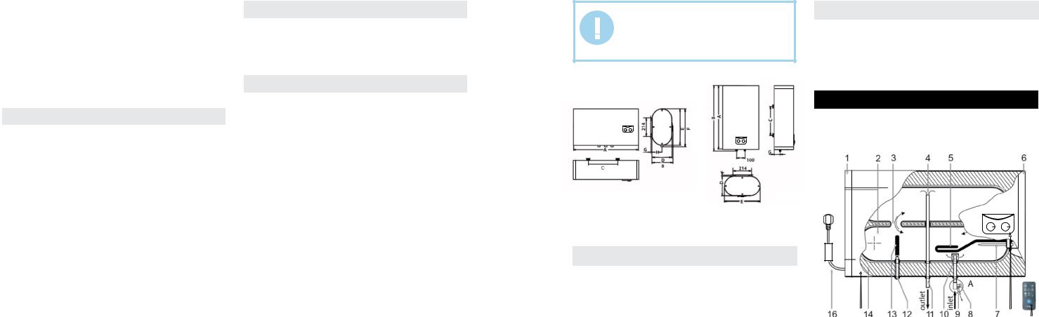
Dimensions |
Series FSM5/FSM3 |
||
|
|
||
Series FSM6/FSM4 |
|
|
|
|
|
||
|
|
|
|
|
|
|
|
|
|
|
|
Fig. 1 |
Fig. 2 |
Dimensions of water heaters (mm) are made in accordance with fig. 1, fig. 2 and fig. 3.
Table 3
|
Capacity, l |
A |
B |
C |
D |
E |
F |
G |
H |
|
|
|
|
|
|
|
|
|
|
|
30 |
550 |
570 |
240 |
238 |
435 |
20 |
73 |
- |
|
|
|
|
|
|
|
|
|
|
SWH FSM5/ |
50 |
855 |
875 |
500 |
238 |
435 |
20 |
73 |
- |
|
|
|
|
|
|
|
|
|
|
SWH FSM3 series |
80 |
991 |
1011 |
450 |
270 |
493 |
20 |
91,5 |
- |
|
|||||||||
|
|
|
|
|
|
|
|
|
|
|
100 |
1190 |
1210 |
550 |
270 |
493 |
20 |
91,5 |
- |
|
|
|
|
|
|
|
|
|
|
|
Capacity, l |
A |
B |
C |
D |
E |
F |
G |
H |
|
|
|
|
|
|
|
|
|
|
|
30 |
550 |
266 |
240 |
238 |
435 |
450 |
20 |
73 |
|
|
|
|
|
|
|
|
|
|
SWH FSM6/ |
50 |
855 |
266 |
500 |
238 |
435 |
450 |
20 |
73 |
|
|
|
|
|
|
|
|
|
|
SWH FSM4 series |
80 |
991 |
298 |
450 |
270 |
493 |
510 |
20 |
91,5 |
|
|||||||||
|
|
|
|
|
|
|
|
|
|
|
100 |
1190 |
298 |
550 |
270 |
493 |
510 |
20 |
91,5 |
|
|
|
|
|
|
|
|
|
|
5. WATER HEATER DESCRIPTION
Fig.3 shows the design of the horizontal-type water heater. Example is FSM6/FSM4.
FSM6/FSM4 series
Fig. 3 |
15 |
17 18 |
4 |
www.timberk.com • electrical storage water heater |
|
www.timberk.com • electrical storage water heater |
5 |
|
|
|
|
|
1 – left composite protective cover
2 – water tanks
3 – system of flows between tanks
4 – the upper part of the hot water intake tube 5 – heating element
6 – right composite protective cover
7 – temperature sensor case
8 – composite pressure safety valve (be sure to install onto the cold water supply tube) Pos. A
9 – emergency discharge of surplus water pressure (a small water leakage is possible from the emergency discharge hole when the water heater is operating. It is normal)
10 – inlet nozzle with a splitter
11 – hot water outlet nozzle
12 – emergency water discharge nozzle (can be used for water discharge during cleaning of the internal tank surface upon its maintenance and anode replacement)
13 – protective magnesium anode
14 – urethane foam heat insulation layer
15 – external stainless steel decorative case
16 – power cable with GFCI*
17 – control panel
18 – remote control (only for FSM5/FSM6 series)
* Depending on the product batch, GFCI can be located not within the power cable electric plug.
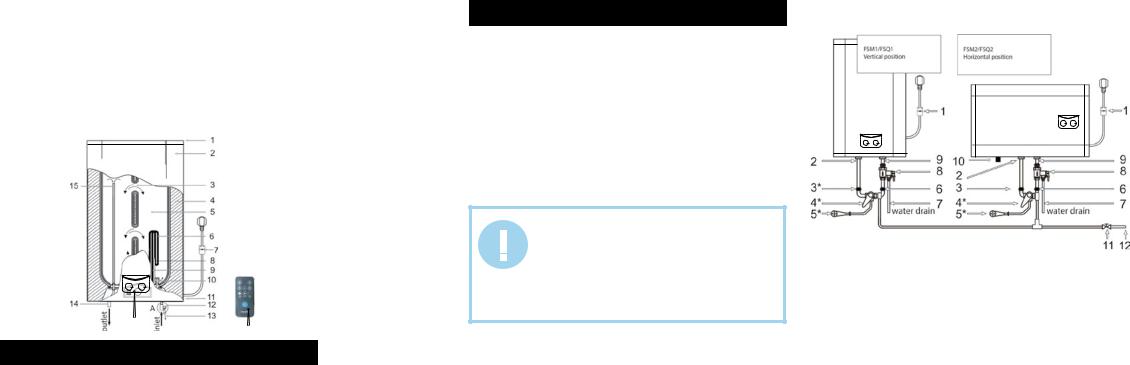
FSM5/FSM3 series
1 – the upper composite protective cover
2 – external decorative case
3 – system of flows
4 – urethane foam heat insulation layer
5 – internal tank
6 – heating element
7 – power cable with GFCI*
8 – thermostat sensor pipe
9 – protective magnesium anode
10 – inlet nozzle with a splitter
11 – the lower composite protective cover
12 – composite pressure safety valve (make sure to install onto the cold water supply tube) Pos. A
13 – emergency discharge of surplus water pressure (a small water leakage is possible from the emergency discharge hole when the water heater is operating. It is normal)
14 – hot water outlet nozzle
15 – the upper part of the hot water intake tube 16 – remote control (only for FSM5/FSM6 series) 17 – control panel
* Depending on the product batch, GFCI can be located not within the power cable electric plug.
|
|
|
|
|
|
|
|
|
|
Fig. 4 |
17 |
16 |
||
|
||||
6. DELIVERY SET
1.Water heater – 1 pc.
2.Anchor bolt – 2 pcs.
3.Pressure safety valve – 1 pc.
4.Discharge pipe – 1 pc.
5.Operation manual – 1 pc.
6.Guarantee card – 1 pc.
7.Packing – 1 pc.
8.Remote control – 1 pc. (only for FSM5/FSM6 series)
7. WATER HEATER INSTALLATION
Location
1.Electric water heater should be mounted on a firm wall. If the wall is not robust enough to hold the weight equal to the doubled weight of the total water heater weight, fully filled with water, then it should be mounted on a special support.
2.The wall, where the electric water heater is to be mounted, must withstand at least the double weight of the water heater, fully filled with water; there must be no cracks and other damages on the wall. Otherwise it is necessary to take measures to strengthen the mounting or mount the water heater on a special support.
3.If a bathroom is too small, the water heater can be installed elsewhere, unexposed to direct sunlight and unavailable for moisture. However, to reduce heat losses in pipelines, the location, where a water heater is to be installed, must be as close to the place, where hot water is used, as possible.
IMPORTANT!
The water heater must be mounted on a vertical wall only the position, specified in Fig.3-4 (FSM5/FSM3 line
– vertically, FSM6/FSM4 – horizontally). Mounting of the appliance in any other position or vertical or horizontal tilting will inevitably result in failure of the water heater, emergency situation and is considered a non-guarantee case by the manufacturer.
Water heater mounting methods
Fig.5 shows the way to mount the water heater for one consumption point.
|
|
|
|
FSM5/FSM3 |
FSM6/FSM4 |
* *
Fig. 5
1.Power cord with GFCI**
2.Water outlet
3.Hot water supply adjustment cock*
4.Mixer*
5.Shower header*
6.Cold water supply adjustment cock*
7.Discharge pipe*
8.Composite pressure-relief valve
9.Water inlet
10.Magnesium anode – water discharge nozzle
11.Water main shut-off valve
12.Water main
*not included in the delivery set
**Depending on the product batch, GFCI can be located not within the power cable electric plug.
6 |
www.timberk.com • electrical storage water heater |
|
www.timberk.com • electrical storage water heater |
7 |
|
|
|
|
|

Fig. 7 shows the way to mount the water heater for one consumption point.
FSM5/FSM3
FSM6/FSM4
Fig. 6
1.Power cord with GFCI**
2.Mounted water heater
3.Composite pressure-relief valve
4.Cold water supply valve*
5.Mixer*
6.Shower header*
7.Water main shut-off valve
8.Discharge pipe
9.Water main
10.Bath*
11.T-joint*
12.Magnesium anode – water discharge nozzle
*not included in the delivery set
**Depending on the product batch, GFCI can be located not within the power cable electric plug.
IMPORTANT!
Please, use accessories, provided by the manufacturer, to install the water heater. Electric water heater must not be mounted on a wall prior you make sure that the bracket is installed firmly and securely. Otherwise the electric water heater may fall down from the wall, which may cause its damage and even serious accidents involving bodily injury. When determining points for bolt holes, it is necessary to provision some spare space between the lower part
of the water heater and the floor, and as to the FSM6/
FSM4 line there also must be some space between the right side of the water heater and the wall on the right, not less than 0.6 m to make it convenient to perform maintenance if necessary.
for FSM6/FSM4 series
for FSM5/FSM3 series
Fig. 7
1. Electric water heater should be mounted on a firm wall. If the wall is not robust enough to hold the weight equal to the doubled weight of the overall water heater weight, fully filled with water, then it should be mounted on a special support.
Fig. 8
2.After you chose the proper place to install the water heater, determine points for holes for expansion hook bolts (to be determined in accordance with the data sheet for the appliance you chose). Drill two holes of the corresponding depth in the wall using a drill, dimensionally fit for expansion bolts, enclosed with the water heater, insert bolts, turn the hook upwards, securely tighten nuts and then hang the electric water heater on these hooks (see Fig. 8).
3.Fix a power outlet to the wall. Requirements to the outlet are as follows: 230V/10A, single-phase, three-wired. It is recommended to place the outlet on the right side above the water heater.
4.If a bathroom is too small, the water heater can be installed elsewhere, unexposed to direct sunlight and unavailable for moisture. However, to reduce heat losses in pipelines, the location, where a water heater is to be installed, must be as close to the place, where hot water is used, as possible.
NOTE:
In places or on the wall, where water may get to, the power outlet installation height must be not less than 1.8 m.
Connection to water main
1. The heater must be connected to water main with at least 0.1 MPa pressure; maximum pressure is 0.7 MPa.
NOTE:
The water heater is the appliance, operating in such a manner that pressure of water in the water heater corresponds to the pressure of water in water main. If pressure in the main exceeds 0.7 MPa, then it is necessary to mount a pressure reducer before the water heater so that pressure doesn’t exceed 0.7 MPa.
2.G1/2 diameter pipes are used to connect the water heater to the water pipeline.
3.To prevent a leakage when connecting pipes, use rubber sealing gaskets on the threaded pipe ends.
4.Screw a relief valve to the inlet nozzle, marked blue and embossed arrow of the water flow direction, so that the water flow direction coincides with direction of the arrow on the valve’s case.
NOTE:
Do not mount additional accessories, such as a shutoff valve, between the relief valve and the inlet nozzle.
5.Water heater with the mounted valve must be connected to the water main – install a shut-off valve at the water inlet point. You need to connect a drain pipe to the opening of the pressure relief of safety valve. Next you should put a drain pipe to the sewer.
6.Connect the desired number of consumption points to the outlet nozzle, marked red.
7.Check leak integrity of joints: open the shut-off cock and one of the cock assemblies. After the tank is filled with water, as evidenced by issue of water from the cock assembly, shut the cock assembly and check the leak integrity of all joints.
8 |
www.timberk.com • electrical storage water heater |
|
www.timberk.com • electrical storage water heater |
9 |
|
|
|
|
|
IMPORTANT!
If water in the installation location contains a large amount of calcium, manganese or iron salts, then IT IS NECESSARY to mount a respective filter in the delivery system to reduce the amount of scale generated in the tank and on the heating element.
Connection to electric main
IMPORTANT!
Prior to connecting the tank water heater, make sure that the water heater is properly grounded. Proper grounding is important to minimize electric shocks and risk of fire. The power cord is equipped with a plug with a grounding pin. The appliance must be used with a properly grounded power outlet. If the outlet, you are intending to use, is not properly grounded or grounded by a time-delay fuse or a circuit breaker, contact a qualified electrician to install a proper outlet.
1.The water heater is designed to be connected to 230V single-phase electric main. Prior to connecting make sure that parameters of the electric main in the place of connection correspond to parameters, specified on the identification plate with technical parameters of the appliance. You should follow the current electrical safety code when installing the water heater.
2.The power outlet must be properly grounded. The outlet must be designed for rated current not less than 10A. The power outlet and plug must always be dry to prevent current leakage. Regularly check if the power plug is tightly connected to the outlet. Do it in the following order: insert the power plug into the outlet, switch off the water heater after halfhour operation and unplug the cord, check if the plug is heated by your hand. If the plug is heated over 50°C, then to prevent damages, accidents and fire as a result of bad electrical contact, replace the outlet with a new one. A specialist must do this.
3.Power cord of the appliance is a single unit with GFCI (Ground Fault Circuit Interrupter).
IMPORTANT!
Wall outlet should be rated on voltage not lower than 10А, electric main cabel with cooper section not lesser then 3х1,5 mm2 (for cooper).
Electric plug of the device corresponds one block with GFCI.
Electric socket should be no lower, than 10A, power card with copper inner part, cross-section of copper should be not less, than 3x1,5 mm2.
Electric plug has combined with GFCI.
IMPORTANT!
To provide reliable operation and safe use of the water heater, prior to the first run check if it is properly connected to the 230V AC mains. The water heater to be connected must be securely linked with the earth circuit of your electric mains. If the water heater is not grounded, then in case of a short circuit GFCI, supplied with the heater, may not operate. It is dangerous.
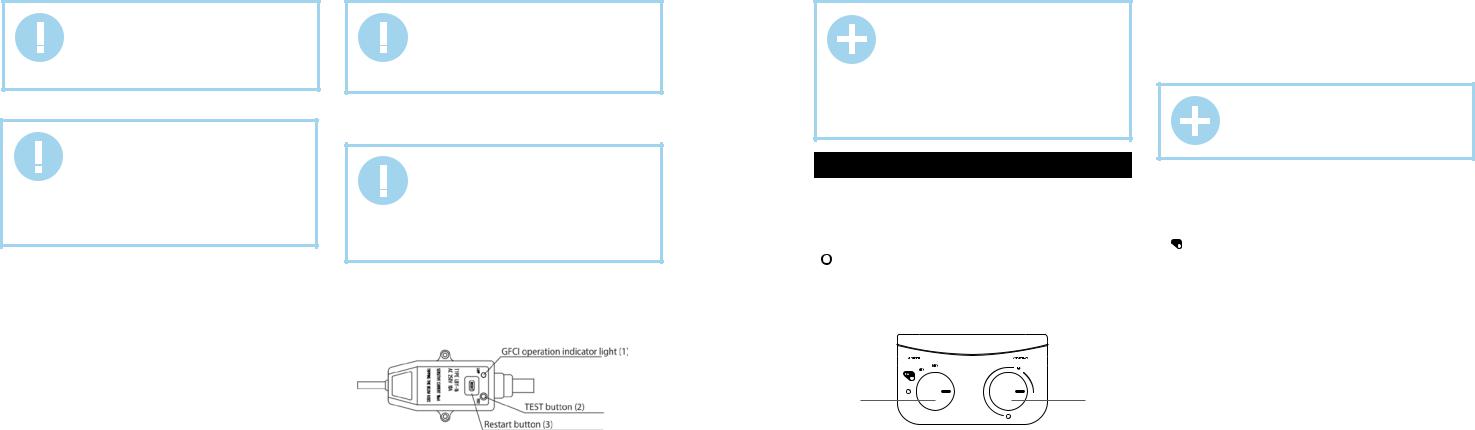
GFCI (Ground Fault Circuit Interrupter) (Fig. 9)
1.Connect the cable to the mains, indicator (1) will light up.
2.Press button (2) for testing, voltage will be cut off, indicator (1) will light down and restart button (3) will go upwards.
3.Press button (3) to restart the appliance, voltage will be restored and indicator (1) will light up.
Fig. 9
NOTE:
-if pressing test button (2) voltage is not cut off and/or indicator (1) continues to be lighted, it means that GFCI safety device is not operating properly.
-if pressing restart button (3) voltage is not restored and/or indicator (1) doesn’t light up, it means that the water heater is not operating properly. In both cases disconnect the water heater and call the service center.
-to reduce the risk of an electric shock, do not disassemble, remove or fill liquid in this appliance.
8.WATER HEATER CONTROL
Control panel of FSM3/FSM4series
1. Thermostat handle
Please, use this handle to set the desired temperature of water. Turning the knob in a clockwise direction you increase temperature of water.
2. Heating mode switcher
« » - means OFF position. Turning the knob in a clockwise direction you increase power from 800W up to 2000W
3. Indicators lighting
If light are blue it means the water heater works, but heating element is off. If lights are blue and red simultaneously it means the heating element heats a water inside tank.
2 |
1 |
Fig. 10
Water heater operation (FSM3/FSM4 series)
1. Switching on
1.1 At first, open one of the hot water outlet valves, then open the cold water supply valve. The electric water heater will start filling with water. When water flows from the hot tap freely, it means the water heater is fully filled with water and you can close the hot water outlet valve.
NOTE:
During normal operation the cold water supply valve must be set “open”.
1.2 Plug the power cord into the outlet, GFCI light must be on and blue light at control panel must be on.
2. Water heating mode setting
To set required mode, please, rotate heating mode setting knob to one of position mentioned below:
-« 
 » - save mode (800 W). In this mode when heating element is on – left red control panel light is on
-«  » - medium heating mode (1200W). In this mode when heating element is on – right red control panel light is on
-«
 » - maximum capacity heating mode (2000 W). In this mode when heating element is on – both right and left red control panel lights are on.
3. Water heating temperature setting.
3.1. Temperature can be set within the range 35°С-75°С, in increments of 1°С.
3.2.To increase water temperature please rotate handle clockwise
3.3.To decrease water temperature please rotate handle counterclockwise
3.4.The water heater automatically maintains water temperature. When water temperature in the water heater reaches the set temperature, the heating element is automatically switched off. When water temperature in the water heater drops to a certain level, the heating is automatically switched on.
10 |
www.timberk.com • electrical storage water heater |
|
www.timberk.com • electrical storage water heater |
11 |
|
|
|
|
|
4. Switching off
To switch off water heater please set thermostat handle and temperature setting knob «  ».
».
At this time only control panel blue light is on. In case you are not going to use water heater for long period – please disconnect it from power supply.
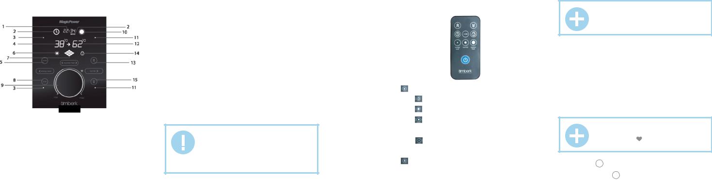
Control panel (for FSM5/FSM6 series)
Fig. 11
1.Time indication
2.Timer activation indicator
It lights up when water heater on/off timer is activated. 3. Energy save indicators
They light up when selecting low heating power (800 W).
4.Water heater water temperature indicator
5.Mode button
It is used to set time and timer, as well as lock the control panel.
6.Night heating activation indicator
7.Heating power indicator
8.Timer button
It is used to activate timer and night heating. 9. Temperature controller handle
It is used to switch on/off the appliance, set the desired heating temperature, as well as select low heating power “energy save” (800 W), medium heating power “normal heat” (1200 W), high heating power “express heat” (2000 W).
When pressed, the temperature controller handle also performs the ON/ OFF button function.
10.Water heating indicator
11.Normal heat indicators
They light up when selecting medium heating power (1200 W).
12.Set temperature indicator
13.button 
It is used to increase the selected value.
14.Control panel lock indicator
15.Button 
It is used to decrease the selected value.
Remote controller (for FSM5/FSM6 series)
The remote controller should be directed to the signal receiver, located on the water heater. The water heater confirms receipt of the control command by a sound signal.
IMPORTANT!
1. Prevent contact of the remote controller with water and other liquids. Prevent contact of the remote controller with direct sunlight and do not leave it nearby heaters and electric appliances.
2. Prevent contact of direct sunlight with the infrared signal receiver on the unit
Mounting of batteries
The remote controller is power supplied from two AA batteries (not included in the set of delivery), installed in a special compartment whose cover is located on the back panel of the remote controller. To mount batteries:
1.Remove the cover of the battery compartment by sliding it along the direction of the arrow.
2.Mount batteries, observing specified polarity.
3.Place the cover back.
9 |
|
|
|
|
|
|
8 |
|
|
|
|
|
1 |
7 |
|
|
|
|
|
2 |
|
|
|
|
|
||
6 |
|
|
|
|
|
3 |
|
|
|
|
|
||
|
|
|
|
|
4 |
|
|
|
|
|
|
5 |
|
Fig. 12
1. « |
» button |
|
It is used to decrease the selected value. |
||
2. Button « |
» |
|
It is used to lock control panel. |
||
3. Button « |
» |
|
It is used to choose «express heat» (2000 W) function.
4. Button « »
It is used to choose «normal heat» (1200 W) function.
5. ON/OFF button
It is used to switch on/off the appliance.
6. Button « »
It is used to choose «energy save» (800 W) function.
7. TIMER button
It is used to activate timer and night heating.
8. « » button
It is used to increase the selected value.
9. MODE button
It is used to set time and timer.
Water heater operation (for FSM5/FSM6 series) 1. Switching on
1.1 At first, open one of the hot water outlet valves, then open the cold water supply valve. The electric water heater will start filling with water. When water flows from the hot tap freely, it means the water heater is fully filled with water and you can close the hot water outlet valve.
NOTE:
During normal operation the cold water supply valve must be set “open”.
1.2Plug the power cord into the outlet, at that an indicator light on GFCI and temperature controller handle lighting will light up and time will be shown on the display.
1.3Press the temperature controller handle and hold it for a few seconds, or press “ON/OFF” button on the remote controller, at that water temperature in the water heater and set water temperature will be shown on the display.
When ON/OFF button is pressed for the first time, the heating element is switched on.
The system is set for 70°C and 2 kW heating power.
2. Water heating temperature setting
2.1. Temperature can be set within the range 35°С-75°С, in increments of 1°С.
NOTE:
When setting temperature, having reached the optimal heating position “ ” (+58°С (+/- 2°С), you will hear a sound signal (for some models).
2.2. Turn the temperature controller handle clockwise (from “min” to “max”) or press button “  ” to increase the water heating temperature.
2.3.Turn the temperature controller handle counterclockwise (from “max” to “min”) or press button “  ” to decrease the water heating temperature.
2.4.The water heater automatically maintains water temperature. When
12 |
www.timberk.com • electrical storage water heater |
|
www.timberk.com • electrical storage water heater |
13 |
|
|
|
|
|
 Loading...