


Thermo Products CHX1-75N, CDX1-75N, CDX1-125N, CHX1-125N, CDX1-100N User Manual 2
...TWO STAGE CONDENSING GAS FURNACE
INSTALLATION AND OPERATION MANUAL
MODELS:
FOR USE WITH NATURAL GAS OR LP GAS (PROPANE)
CHX1-75N CDX1-75N
CHX1-100N CDX1-100N
CHX1-125N CDX1-125N


 : IF YOU DO NOT FOLLOW THE SAFETY PRECAUTIONS BELOW AND IN THIS MANUAL, A FIRE OR EXPLOSION MAY RESULT CAUSING PROPERTY DAMAGE, PERSONAL INJURY, OR LOSS OF LIFE.
DO NOT STORE OR USE GASOLINE OR OTHER FLAMMABLE VAPORS AND LIQUIDS IN THE VICINITY OF THIS OR ANY OTHER APPLIANCE.
WHAT TO DO IF YOU SMELL GAS:
•DO NOT TRY TO LIGHT ANY APPLIANCE.
•DO NOT TOUCH ANY ELECTRICAL SWITCH; DO NOT USE ANY PHONE IN YOUR BUILDING.
•LEAVE THE BUILDING IMMEDIATELY.
•IMMEDIATELY CALL YOUR GAS SUPPLIER FROM A NEIGHBOR’S PHONE. FOLLOW THE GAS SUPPLIER’S INSTRUCTIONS.
•IF YOU CANNOT REACH YOUR GAS SUPPLIER; CALL THE FIRE DEPARTMENT.
INSTALLATION AND SERVICE MUST BE PERFORMED BY A QUALIFIED INSTALLER, SERVICE AGENCY OR THE GAS SUPPLIER. (REFERRED TO IN THESE INSTRUCTIONS AS A QUALIFIED HEATING CONTRACTOR).
PLEASE READ THESE INSTRUCTIONS PRIOR TO INSTALLATION, INITIAL FIRING, AND BEFORE PERFORMING ANY SERVICE OR MAINTENANCE. THESE INSTRUCTIONS MUST BE LEFT WITH THE HOMEOWNER AND SHOULD BE RETAINED FOR FUTURE REFERENCE BY QUALIFIED SERVICE PERSONNEL.
THERMO PRODUCTS, LLC.
BOX 217
NORTH JUDSON, IN 46366
PHONE: (574) 896-2133
MADE IN USA
MG-1010
ECN4470-MA

All installations and services must be performed by qualified service personnel.
I. SAFETY INFORMATION
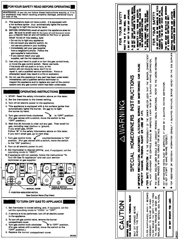
This and the following page contain reproductions of the various warning and instruction labels placed on the Thermo Pride Two Stage Condensing Gas Furnaces. Please read and comply with the contents of these labels.
i
All installations and services must be performed by qualified service personnel.
This and the previous page contain reproductions of the various warning and instruction labels placed on the Thermo Pride Two Stage Condensing Gas Furnaces. Please read and comply with the contents of these labels.
The following safety information should be read, understood, and followed by the installer.
ii

All installations and services must be performed by qualified service personnel.
1.Use only with type of gas approved for this furnace. Refer to furnace rating plate.
2.Connect this furnace to an approved vent system only. Combustion products must be carried outdoors. Refer to Section III, D thru H, of this manual.
The following pages contain various warnings and cautions found throughout the Thermo Pride Highboy and Dual Poise Two Stage Condensing Gas Furnace Manual. Please read and comply with the statements below.


 : This furnace is not to be used for temporary heating of buildings or structures under construction.


 : These high efficiency condensing furnaces are not certified for and shall not be vented into a standard or any type of chimney.


 : These furnaces may not be common vented with any other appliance.


 : The vent and air intake elbows must be kept away from bushes, shrubs or any vegetation that may restrict the flow of flue products. It must also be kept clear of any leaves, weeds or other combustible materials. Keep the vent hood clear of snow. Avoid locating the terminals in areas where standing water or condensate drippage may be a problem.


 : Outside combustion air must not come from an area that is directly adjacent to a pool, hot tub or spa. Measures should be taken to prevent the entry of corrosive chemicals or vapors to the combustion and ventilation air supply. Such chemicals include but are not limited to chlorinated and/or fluorinated hydrocarbons such as found in refrigerants, aerosol propellants, dry cleaning fluids, degreasers and removers. Other harmful compounds may come from bleaches, air fresheners or mastics. Vapors from such products can form acid compounds when burned in a gas flame. Should acid compounds form in your furnace; it may reduce the life of the furnace.


 : Because of the potential of odorant fade, a gas leak may not be detected by smell. If this furnace is installed below grade, contact your gas supplier for a gas detector.


 : Turn off power to furnace before it is placed into service. The gas piping system must have been leak tested by a qualified heating contractor.


 : It may be necessary to purge the air out of the gas line for initial start-up of the furnace after installation. This should be done by a qualified heating contractor. If excessive gas escapes when purging the gas supply at the union, allow the area to ventilate for at least 15 minutes before attempting to start the furnace. LP gas is especially dangerous because the specific gravity of LP gas allows it to accumulate at floor level at a dangerous concentration. For remainder of operating instructions, reference Users Information Manual.


 : Heat exchanger oil will burn off on initial firing creating an unpleasant odor. To prevent this odor from occurring more than once, it is suggested that:
1.A window(s) be opened.
2.The thermostat set at highest setting.
3.The furnace remain running at conditions 1&2 for 30 minutes or until odor has dissipated.


 : The CHX1/CDX1 furnace models are sealed combustion design, which does not require an air shutter adjustment (air shutters are not used) for proper flame characteristics. Burner box access cover must always be secured with all screws in place and tightened before operating furnace.
iii

All installations and services must be performed by qualified service personnel.


 : Personal injury or property damage could result from repair or service of this furnace by anyone other than a qualified heating contractor. Only the homeowner/user routine maintenance described in the Users Information Manual may be performed by the user.
iv
All installations and services must be performed by qualified service personnel.
|
|
INDEX |
|
SECTION |
|
BEGINNING PAGE |
|
I. |
SAFETY INFORMATION |
i |
|
II. |
FURNACE SPECIFICATIONS |
1 |
|
III. |
GENERAL INSTALLATION |
6 |
|
|
A. CODES AND CLEARANCES |
6 |
|
|
B. FURNACE LOCATION |
7 |
|
|
B1.CDX1 HORIZONTAL APPLICATION |
7 |
|
|
C. REPLACING EXISTING FURNACE FROM A COMMON VENT |
9 |
|
|
D. GENERAL REQUIREMENTS FOR VENTING CHX1/CDX1 |
9 |
|
|
E. SIDEWALL VENTING |
10 |
|
|
E1. SINGLE PIPE (SIDEWALL) VENTING OPTION |
12 |
|
|
F. INSTALLATION OF OUTSIDE VENT/AIR INTAKE TERMS. |
13 |
|
|
G. CONNECTING FURNACE TO VENT/AIR INTAKE TERMS. |
14 |
|
|
H. CONNECTING FURNACE TO ROOF VENT/AIR TERMS. |
19 |
|
|
I. CONDENSATE DRAIN LINE & TRAP ASSY. |
20 |
|
|
J. GENERAL GAS PIPING |
22 |
|
|
K. FILTERS |
|
23 |
|
L. WIRING |
|
25 |
IV. |
STARTING THE UNIT |
29 |
|
|
A. SEQUENCE OF OPERATIONS |
29 |
|
|
B. INITIAL START-UP |
32 |
|
|
C. FURNACE CHECKOUT PROCEDURE |
40 |
|
V. |
INSTALLER’S INSTRUCTIONS TO USER |
40 |
|
VI. |
TROUBLESHOOTING |
41 |
|
APPENDIX – A |
REPLACEMENT PARTS LIST |
48 |
|
APPENDIX – B |
WIRING DIAGRAMS |
52 |
|
v
All installations and services must be performed by qualified service personnel.
II. FURNACE SPECIFICATIONS
CHX1 SERIES
MODEL NO. |
CHX1-75 |
CHX1-100 |
CHX1-125 |
|
BTU/HR INPUT (High fire/ Low fire) |
75,000 / 52,000 |
100,000 / 70,000 |
125,000 / 87,500 |
|
BTU/HR OUTPUT (High fire/ Low fire) |
70,875 / 49,612 |
94,500 / 66,150 |
117,500 / 82,250 |
|
|
|
|
|
|
HEIGHT OF CASING |
44-1/4” |
44-1/4” |
44-1/4” |
|
WIDTH OF CASING |
17” |
21” |
24” |
|
DEPTH OF CASING |
27-1/2” |
27-1/2” |
27-1/2” |
|
WARM AIR OUTLET |
15 x 18 |
19 x 18 |
22 x 18 |
|
RETURN AIR INLET |
25 x 16 |
25 x 16 |
25 x 16 |
|
|
|
|
|
|
DIA. OF FLUE |
2” |
3” |
3” |
|
DIA. OF COMBUSTION |
2” |
3” |
3” |
|
AIR INTAKE |
||||
|
|
|
||
|
|
|
|
|
CFM from .2” & .5” w.c. |
COOLING |
COOLING |
COOLING |
|
EXTERNAL STATIC PRESSURE |
||||
|
|
|
||
@COOLING TAP A |
1000 |
1200 |
1400 |
|
@COOLING TAP B |
800 |
1000 |
1200 |
|
@COOLING TAP C |
1200 |
1400 |
1600 |
|
@COOLING TAP D |
1400 |
1600 |
2000 |
|
|
|
|
|
|
|
HEATING |
HEATING |
HEATING |
|
@HEATING TAP A (High fire/Low fire) |
931 / 760 |
1243 / 1015 |
1556 / 1270 |
|
|
|
|
|
|
TEMPERATURE RISE |
70 / 60 |
70 / 60 |
70 / 60 |
|
BLOWER MOTOR HP |
.5 |
.75 |
1 |
|
|
|
|
|
|
POWER CHOKES |
- |
2.65 Mh |
2.1 Mh |
|
LARGEST RECOMMEDED |
3.5 Ton |
4 Ton |
5 Ton |
|
AIR CONDITIONER |
||||
|
|
|
||
SIZE OF FILTERS |
24-3/4” x 15-3/4” |
24-3/4” x 15-3/4” |
24-3/4” x 19-3/4” |
|
NOTES: |
|
|
|
1.BTU output based on annual fuel utilization efficiency rated by manufacturer.
2.On all outlet and inlet dimensions, the first dimension is width.
3.To permit largest recommended air conditioning (at .5 static pressure), selection of the highest motor speed is required.
1
All installations and services must be performed by qualified service personnel.
CDX1 SERIES
MODEL NO. |
CDX1-75 |
CDX1-100 |
CDX1-125 |
|
BTU/HR INPUT (High fire / Low fire) |
75,000 / 56,250 |
100,000 / 75,000 |
125,000 / 93,750 |
|
BTU/HR OUTPUT (High fire / Low fire) |
69,750 / 52,312 |
93,000 / 69,750 |
116,250 / 87,187 |
|
|
|
|
|
|
HEIGHT OF CASING |
46-1/4” |
46-1/4” |
46-1/4” |
|
WIDTH OF CASING |
17” |
21” |
24” |
|
DEPTH OF CASING |
27-1/2” |
27-1/2” |
27-1/2” |
|
WARM AIR OUTLET |
15 x 18 |
19 x 18 |
22 x 18 |
|
RETURN AIR INLET |
15 x 22 |
19 x 22 |
22 x 22 |
|
|
|
|
|
|
DIA. OF FLUE |
2” |
3” |
3” |
|
DIA. OF COMBUSTION |
2” |
3” |
3” |
|
AIR INTAKE |
||||
|
|
|
||
|
|
|
|
|
CFM from .2” & .5” w.c. |
COOLING |
COOLING |
COOLING |
|
EXTERNAL STATIC PRESSURE |
||||
|
|
|
||
|
|
|
|
|
@COOLING TAP A |
1000 |
1200 |
1400 |
|
@COOLING TAP B |
800 |
1000 |
1200 |
|
@COOLING TAP C |
1200 |
1400 |
1600 |
|
@COOLING TAP D |
1400 |
1600 |
2000 |
|
|
|
|
|
|
|
HEATING |
HEATING |
HEATING |
|
@HEATING TAP C (High fire / Low fire) |
1012 / 826 |
1340 / 1094 |
1673 / 1366 |
|
|
|
|
|
|
TEMPERATURE RISE |
65 / 60 |
65 / 60 |
65 / 60 |
|
BLOWER MOTOR HP |
.5 |
.75 |
1 |
|
|
|
|
|
|
POWER CHOKES |
- |
2.65Mh |
2.1Mh |
|
LARGEST RECOMMEDED |
3.5 Ton |
4 Ton |
5 Ton |
|
AIR CONDITIONER |
||||
|
|
|
||
SIZE OF FILTERS |
21-3/4” x 14”(2) |
21-3/4” x 14”(2) |
21-3/4” x 14”(2) |
|
NOTES: |
|
|
|
1.BTU output based on annual fuel utilization efficiency rated by manufacturer.
2.On all outlet and inlet dimensions, the first dimension is width.
3.To permit largest recommended air conditioning (at .5 static pressure), selection of the highest motor speed is required.
4.Electrical characteristics at 115 volts, 60 Hz., 1 phase (less than 15 amps. for all models).
5.All specifications are subject to change without notice.
2
All installations and services must be performed by qualified service personnel.
INSTALLATION PARTS PACKAGES – CHX1-75
PARTS PACKAGE |
DESCRIPTION |
PART # |
QUANTITY |
|
#S00S4378 |
||||
|
|
|
||
|
2-3/8” ID radiator hose |
410017 |
1 |
|
|
Thermostat lead bushing |
350750 |
1 |
|
|
PVC trap assembly |
320816 |
1 |
|
|
#8 x ¾ coated TEK screws for |
300283 |
4 |
|
|
mounting trap & inlet/outlet collars |
|||
|
|
|
||
|
11/16” OD x 1/2” ID vinyl tubing |
410060 |
24” |
|
|
2 x 4 electrical J-box |
350024 |
1 |
|
|
2 x 4 electrical J-box cover |
350020 |
1 |
|
|
#8 x ½ TEK screws for |
300208 |
2 |
|
|
mounting 2 x 4 J-box |
|||
|
|
|
||
|
#10-32 x ½ green ground screw |
300109 |
1 |
|
|
#10-32 hex nut |
300110 |
1 |
|
|
3/16” dia. star washer |
300270 |
1 |
|
|
Grounding instructions |
MG-966 |
1 |
|
|
Wire nut |
300132 |
2 |
|
|
3” stainless steel hose clamp |
300276 |
2 |
|
|
J-box wire bushing |
350016 |
1 |
|
|
Drain hose grommet |
350446 |
1 |
|
|
Spring clamp, 11/16” |
300299 |
3 |
|
|
Installation notice |
MG-987 |
1 |
|
|
PVC tee assembly, 2” dia. |
320818 |
1 |
|
INSTALLATION PARTS PACKAGES – CHX1-100-125 |
|
|
||
|
|
|
|
|
PARTS PACKAGE |
DESCRIPTION |
PART # |
QUANTITY |
|
#S00S4379 |
||||
|
|
|
||
|
2-3/8” ID radiator hose |
410017 |
1 |
|
|
Thermostat lead bushing |
350750 |
1 |
|
|
PVC trap assembly |
320816 |
1 |
|
|
#8 x ¾ coated TEK screws for |
300283 |
4 |
|
|
mounting trap & inlet/outlet collars |
|||
|
|
|
||
|
11/16” OD x ½” ID vinyl tubing |
410060 |
24” |
|
|
2 x 4 electrical J-box |
350024 |
1 |
|
|
2 x 4 electrical J-box cover |
350020 |
1 |
|
|
#8 x ½ TEK screws for |
300208 |
2 |
|
|
mounting 2 x 4 J-box |
|||
|
|
|
||
|
#10-32 x ½ green ground screw |
300109 |
1 |
|
|
#10-32 hex nut |
300110 |
1 |
|
|
3/16” dia. star washer |
300270 |
1 |
|
|
Grounding instructions |
MG-966 |
1 |
|
|
Wire nut |
300132 |
2 |
|
|
3” stainless steel hose clamp |
300276 |
2 |
|
|
J-box wire bushing |
350016 |
1 |
|
|
Drain hose grommet |
350446 |
1 |
|
|
Spring clamp, 11/16” |
300299 |
3 |
|
|
Installation notice |
MG-987 |
1 |
|
|
PVC tee assembly, 2 x 3” dia. |
320817 |
1 |
|
3
All installations and services must be performed by qualified service personnel.
INSTALLATION PARTS PACKAGES – CDX1-75
PARTS PACKAGE |
DESCRIPTION |
PART # |
QUANTITY |
|
#S00S4380 |
||||
|
|
|
||
|
2-3/8” ID radiator hose |
410017 |
1 |
|
|
Thermostat lead bushing |
350750 |
1 |
|
|
PVC trap assembly |
320816 |
1 |
|
|
#8 x ¾ coated TEK screws for |
300283 |
6 |
|
|
mounting trap & inlet/outlet collars |
|||
|
|
|
||
|
11/16” OD x ½” ID vinyl tubing |
410060 |
24” |
|
|
2 x 4 electrical J-box |
350024 |
1 |
|
|
2 x 4 electrical J-box cover |
350020 |
1 |
|
|
#8 x ½ TEK screws for |
300208 |
2 |
|
|
mounting 2 x 4 J-box |
|||
|
|
|
||
|
#10-32 x ½ green ground screw |
300109 |
1 |
|
|
#10-32 hex nut |
300110 |
1 |
|
|
3/16” dia. star washer |
300270 |
1 |
|
|
Grounding instructions |
MG-966 |
1 |
|
|
Wire nut |
300132 |
2 |
|
|
3” stainless steel hose clamp |
300276 |
2 |
|
|
J-box wire bushing |
350016 |
1 |
|
|
Drain hose grommet |
350446 |
1 |
|
|
Spring clamp, 11/16” |
300299 |
3 |
|
|
Installation notice |
MG-987 |
1 |
|
|
PVC tee assembly, 2” dia. |
320819 |
1 |
|
|
Pipe 2” dia. PVC 15” |
14401 |
1 |
|
|
Bracket |
14406 |
1 |
4
All installations and services must be performed by qualified service personnel.
INSTALLATION PARTS PACKAGES – CDX1-100-125
PARTS PACKAGE |
DESCRIPTION |
PART # |
QUANTITY |
|
#S00S4381 |
||||
|
|
|
||
|
2-3/8” ID radiator hose |
410017 |
1 |
|
|
Thermostat lead bushing |
350750 |
1 |
|
|
PVC trap assembly |
320816 |
1 |
|
|
#8 x ¾ coated TEK screws for |
300283 |
4 |
|
|
mounting trap & inlet/outlet collars |
|||
|
|
|
||
|
11/16” OD x 1/2” ID vinyl tubing |
410060 |
24” |
|
|
2 x 4 electrical J-box |
350024 |
1 |
|
|
2 x 4 electrical J-box cover |
350020 |
1 |
|
|
#8 x ½ TEK screws for |
300208 |
2 |
|
|
mounting 2 x 4 J-box |
|||
|
|
|
||
|
#10-32 x ½ green ground screw |
300109 |
1 |
|
|
#10-32 hex nut |
300110 |
1 |
|
|
3/16” dia. star washer |
300270 |
1 |
|
|
Grounding instructions |
MG-966 |
1 |
|
|
Wire nut |
300132 |
2 |
|
|
3” stainless steel hose clamp |
300276 |
2 |
|
|
J-box wire bushing |
350016 |
1 |
|
|
Drain hose grommet |
350446 |
1 |
|
|
Spring clamp, 11/16” |
300299 |
3 |
|
|
Installation notice |
MG-987 |
1 |
|
|
PVC tee assembly, 2 x 3” dia. |
320817 |
1 |
|
|
PVC tee assembly, 2” dia. |
320819 |
1 |
|
|
Pipe 2” dia. PVC 15” |
14401 |
1 |
|
|
Bracket |
14406 |
1 |
|
|
Reducer 2” x 3” PVC |
320067 |
1 |
5

All installations and services must be performed by qualified service personnel.
III. GENERAL INSTALLATION
These Category Type IV furnaces are shipped completely assembled and wired (internally). See the Dealer Receiving and Freight Claim Procedure Section of the price guide for parts shortage or damage. The furnace and duct system must be adjusted to obtain a temperature rise of 55°F to 85°F through the furnace after installation. (See rating label located on side panel inside the furnace vestibule). The installation must conform with local codes, or in the absence of local codes, with the National Fuel Gas Codes (ANSI Z223.1 or latest edition) and with these instructions.


 : This furnace is not to be used for temporary heating of buildings or structures under construction.
Many of the chemicals used during construction, when burned, form acid bearing condensate that can substantially reduce the life of the heat exchanger.
A. CODES AND CLEARANCES
The following items must be considered when choosing the size and location of the furnace.
1.All local codes and/or regulations take precedence over the instructions in this manual and should be followed accordingly. In the absence of local codes, installation must conform with these instructions, regulations of the National Fire Protection Association, provisions of National Electrical Code (ANSI/NFPA70 or latest edition), and the National Fuel Gas Code (ANSI Z223.1 or latest edition).
2.The BTU output capacity of the furnace proposed for installation should be based on a heat loss calculation made according to the manuals provided by the Air Conditioning Contractors of America (ACCA) or ASHRAE.
3.MINIMUM CLEARANCES TO COMBUSTIBLE MATERIALS
TABLE 1
MODEL NO. |
FROM SIDES OF |
FRONT |
TOP OF |
FROM THE |
SIDE OF |
|
FURNACE & REAR |
PLENUM |
FLUE OR VENT |
PLENUM |
|||
|
|
|||||
CHX1-75 |
0 IN. |
6 IN. |
0 IN. |
0 IN. |
1 IN. |
|
CHX1-100 |
0 IN. |
6 IN. |
0 IN. |
0 IN. |
1 IN. |
|
CHX1-125 |
0 IN. |
6 IN. |
0 IN. |
0 IN. |
1 IN. |
|
CDX1-75 |
0 IN. |
6 IN. |
0 IN. |
0 IN. |
1 IN. |
|
CDX1-100 |
0 IN. |
6 IN. |
0 IN. |
0 IN. |
1 IN. |
|
CDX1-125 |
0 IN. |
6 IN. |
0 IN. |
0 IN. |
1 IN. |
The CHX1-75, 100 and 125 furnaces may be installed on combustible flooring. The furnace shall not be installed directly on carpeting, tile or other combustible material other than wood flooring.
The CDX1-75, 100 and 125 furnaces are to be installed on non-combustible flooring only. The noncombustible floor bases model no. 50 CA base for CDX1-75 model no. 100 CA base for the model no. CDX1-100 and model no. 125 CA base for CDX1-125 are available for the counterflow furnaces to allow their installations on combustible flooring.
These furnaces may be installed in an alcove or in a closet if the minimum clearances to combustible construction (listed previously) are met. The CDX1 series furnaces may be installed in an attic or crawl space. Refer to section III, B1 of this installation manual.
The minimum clearances are listed for fire protection. Clearance for servicing the front of the furnaces and to all points on the furnace requiring access must be 24”*.
*For horizontal furnace installation, refer to section III, B1 of this installation manual.
6

All installations and services must be performed by qualified service personnel.
Equipment must be installed in accordance with regulations of the National Board of Fire Underwriters. Authorities having jurisdiction should be consulted before installations are made.
B. FURNACE LOCATION


 : These high efficiency condensing furnaces are not certified for and shall not be vented into a standard or any type of chimney.
The following shall be considered for locating the furnace:
1.For best performance locate the furnace so that it is centralized with respect to the duct system and as near as possible to a floor drain since condensate drainage must be provided.
2.Place the unit so that proper venting can be achieved, with a minimum number of elbows, in accord with the instructions in this manual.
3.The furnace must be located on a level, dry surface. The furnace must be installed so that the electrical components are protected from water. If the area becomes wet or damp at times, the furnace should be raised above the floor using a concrete base, bricks, patio blocks, etc.
NOTICE: Ensure furnace is level after installation to ensure proper drainage and operation.
4.This furnace must be connected to a drain in accordance with these instructions. If it is not practical to connect the unit to a drain, a condensate pump must be used and can be ordered as an accessory, part number 350225. If an acid neutralizer kit is required by local code or the customer, it is available under part number 320095.
B1. CDX1 HORIZONTAL APPLICATION
The CDX1-75, 100, and 125 furnaces may be installed in a horizontal position by placing the furnace on the left or right side (as viewed from the front in the upright position).
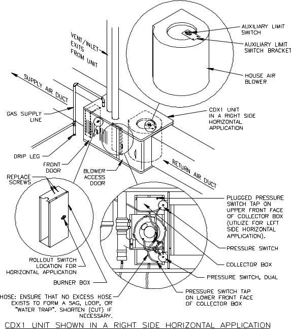
For left or right horizontal applications of the CDX1 series units, the rollout switch located on the burner box must be moved to the pre-punched mounting holes on the side of the burner box. Screws are provided in pre-punched holes at the required limit location. Remove these screws and use them to mount the limit to new location. Utilize previously removed limit mounting screws to fill voided holes at previous limit location (See Figure 1).
For a right side horizontal application of the CDX1 series units, the hose from the single tap pressure switch (top switch) is already connected correctly (See Figure 1).
For a left side horizontal application of the CDX1 series units, the hose from the single tap pressure switch (bottom switch) must be moved to the lower front tap on the face of the collector box. Use the black cap removed from this tap to plug the original pressure switch tap.
NOTE: The hose, when moved, must be shortened (cut) to ensure that no excess hose exists to cause a sag, loop, or "water trap".
For a right side horizontal application of the CDX1 series units, the auxiliary limit switch located on the right side of the house air blower must be moved to the bracket on the opposite (left) side of the blower (See Figure 1).
7
All installations and services must be performed by qualified service personnel.
NOTE: When the CDX1 is installed as horizontal unit, it is imperative that the auxiliary limit switch and bracket be located on the upper side of the house air blower; the burner rollout switch located on the burner box be relocated to the side of the burner box; and that the hose from the single tap pressure switch be connected to the lower tap on the front of the collector box (See Figure 1).
Figure 1
The horizontal furnace installation should be on a service platform large enough to allow for proper clearances on all sides and service access to the front of the furnace (See Table 1). If the furnace is suspended, it must be supported at both ends and in the middle with clearance allowed for removal of both access doors. Gas supply line contact is only permissible between lines formed by the intersection of the top and two sides of the furnaces casing and the building joists, studs, or framing (See Figure 1).
8

All installations and services must be performed by qualified service personnel.
Equipment must be installed in accordance with regulations of the National Board of Fire Underwriters and the National Fuel Gas Code. Authorities having jurisdiction should be consulted before installations are made.
C. REPLACING AN EXISTING FURNACE FROM A COMMON VENT


 : These furnaces may not be common vented with any other appliance.
D. GENERAL REQUIREMENTS FOR VENTING CHX1/CDX1
The CHX1/CDX1 furnace venting system must be installed by a qualified service person in accordance with local codes, the National Fuel Gas Code (NFPA 54/ANSI Z223.1 or latest edition) and these instructions.
The following items and local code requirements must be followed:
1.The vent/air intake terminations outlined by Thermo Products in this manual must be used.
2.The entire vent/air intake system must be made of PVC Schedule 40 pipe.
NOTE: All CHX1/CDX1 furnaces recommended to be installed with outside combustion air.
3.The flue vent pipe and combustion air pipe must be at least as large as the exhaust vent/air intake pipe specified by Thermo Products. No reduction in size is permissible. The CHX1, CDX1-75 requires 2” Schedule 40 PVC pipe. The (CHX1, CDX1)-100 and 125 require 3” Schedule 40 PVC pipe.
4.This CHX1/CDX1 furnace shall not be common vented with any other appliance including those burning solid fuels.
5.Horizontal runs of exhaust vent pipe shall slope upward at least 1/4” per foot from the outlet of the furnace (CHX1’s) or the outlet of the drain tee (CDX1’s) to the vent termination at the outside wall. This will permit proper drainage of the condensate. Horizontal runs of inlet vent pipe shall slope downward at least 1/4” per foot from the outlet of the last elbow or last horizontal run, before exiting the wall, to the vent termination at the outside wall.
6.The vent pipe must be supported every 4 feet and at every joint to prevent pipe blockage caused by condensate trapped by a sag in the vent.
7.The maximum permissible vent length of straight pipe and number of elbows permitted for the exhaust vent and combustion air inlet is shown in Table 2. The elbows shown are in addition to the length of straight pipe permitted. When counting elbows, all elbows used in the exhaust vent or combustion air intake must be counted. This includes elbows used inside the furnace jacket and termination elbows. In addition, up to three elbows may be dropped and the vent length extended five feet for each elbow dropped.
MAXIMUM VENT LENGTH
TABLE 2
VENT SIZE |
|
2 IN. PVC |
|
|
3 IN. PVC |
|
FURNACE |
VENT |
EXHAUST |
COMBUSTION |
VENT |
EXHAUST |
COMBUSTION |
MODEL |
LENGTH |
VENT |
AIR INTAKE |
LENGTH |
VENT |
AIR INTAKE |
|
(FT.) |
ELBOWS (NO.) |
ELBOWS (NO.) |
(FT.) |
ELBOWS (NO.) |
ELBOWS (NO.) |
CHX1/CDX1-75 |
35 |
8 1, 2 |
7 2 |
- |
- |
- |
CHX1/CDX1-100 |
|
NOT PERMITTED |
35 |
8 1, 2 |
7 2 |
|
CHX1/CDX1-125 |
|
NOT PERMITTED |
35 |
8 1, 2 |
7 2 |
|
9
All installations and services must be performed by qualified service personnel.
NOTES:
1The drain tee supplied with CHX1/CDX1 furnaces count as 1 elbow.
2(2) 45° elbows can be substituted for (1) 90° elbow.
Care should be taken to plan out the vent system to be as short as possible (but not shorter than 8 ft.) and to contain as few elbows as possible to insure the best possible operation of the furnace.
8.A hack saw may be used to cut the PVC pipe. It must be cut smoothly at right angles with all burrs removed. All joints must use standard PVC Schedule 40 elbows and couplings. Joints are not to be made by gluing and butting together the cut or raw edges of the vent pipe. The joints inside the vestibule should be sealed with a silicone caulk to allow for maintenance.
Note: Do not use silicone caulk to seal the PVC sleeve or coupling to the metal air intake collar on the burner box. The screw securing the sleeve or coupling to the collar is sufficient.
9.Vent connections shall be checked for leakage with the furnace induced draft blower running and with the vent termination blocked. A mild soap and water solution may be used to check for leaks.
10.Vent pipe passing through an unheated space must be insulated with 1.0” thick foil faced fiberglass insulation or it’s equivalent to prevent freezing of any condensate within the pipe.
11.Minimum clearance from the PVC pipe to combustible material is zero inches.
12.Screens are not required by Thermo Products for the vent and intake. However, optional stainless steel screens are available from Thermo Products, should the homeowner request them.
IMPORTANT: The CHX1/CDX1 furnace models may be vented either through the sidewall or roof. For sidewall instructions continue reading the following section. For roof venting refer to Section III, H, of this manual.
E. SIDEWALL VENTING
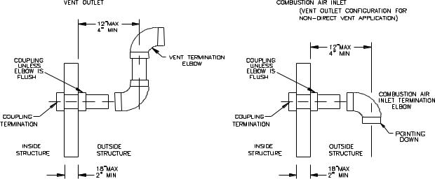
1.The maximum wall thickness through which the vent and combustion air pipes may pass is 18” and the minimum is 2”. The maximum distance from the outer wall to the center of the elbow is 12” (See Figure 2).
Figure 2
10
All installations and services must be performed by qualified service personnel.
NOTICE: If exterior sidewall building materials are subject to degradation from flue gases or moisture, a minimum 12” diameter shield made from stainless steel or high density plastic shall be used for protection.
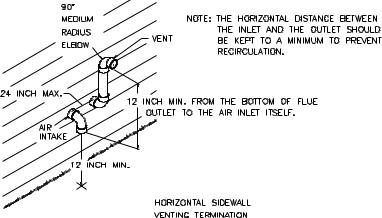
2.The PVC vent termination elbow must be installed in accord with local codes and these instructions. The bottom edge of the vent termination elbow must be installed at least 12 in. above the outlet of the combustion air intake termination elbow and must be installed in the same atmospheric pressure zone (i.e. on the same wall). It is recommended that the horizontal distance between the inlet and flue termination be kept to a minimum when possible and not exceed 24 in. apart. The vent and air intake should utilize the same numbers of elbows and approximately the same length of straight pipe to reach the outside termination elbows. (See Figures 2 & 3).
Figure 3
3. VENT TERMINAL LOCATION REQUIREMENTS
a.The vent terminal shall be located at least 3 ft. above any forced air inlet located within 10 ft.
b.The terminal shall be at least 1 ft. below, 1 ft. horizontally from or 1 foot above any door, window or gravity air inlet into any building. The bottom of the vent terminal shall be located at least 18 in. above grade.
c.The terminal shall not be located over public walkways or over an area where condensate or vapor could create a nuisance or hazard or could be detrimental to the operation of regulators, relief valves or other equipment.
d.A minimum horizontal clearance of 4 ft. must be maintained from electric meters, gas meters, regulators and relief equipment. The vent terminal shall not be installed over these or any other equipment where condensate or vapor could be detrimental to the operation of this equipment and/or controls.
e.The unit shall be located so a minimum of 1/4" per foot upward slope can be maintained from the furnace to the terminal outlet and 1/4” per foot downward slope for the last horizontal run of inlet, to the outside inlet terminal.
f.The vent discharge must be installed a minimum of 12” above grade, 14” from any obstruction and three feet from an inside corner of an L-shaped structure.
11

All installations and services must be performed by qualified service personnel.
Figure 4


 : The vent and air intake elbows must be kept away from bushes, shrubs or any vegetation that may restrict the flow of flue products. It must also be kept clear of any leaves, weeds or other combustible materials. Keep the vent hood clear of snow. Avoid locating the terminals in areas where standing water or condensate drippage may be a problem.
VENT TERMINAL LOCATION GUIDELINES
In addition to following the requirements outlined by local codes, utilizing the guidelines below when possible in locating the vent terminal will help insure the trouble-free operation of your horizontally vented furnace:
•Avoid locating the vent terminal on a wall facing the prevailing winds and wide open areas.
•When this is not practical, choose locations that protect the vent from strong winds such as behind a fence or hedge. NOTICE: The vent terminal must be located a sufficient distance from bushes, shrubs, and vegetation so as not to have the flue products restricted or blocked from such vegetation.
•In areas with considerable snowfall, it is advisable to locate the vent terminal higher than the minimum 12 in. above the ground as to prevent blockage by snow accumulation or drifting.
Measures should be taken to prevent the entry of corrosive chemicals or vapors to the combustion and ventilation air supply. Such chemicals include but are not limited to chlorinated and/or fluorinated hydrocarbons such as found in refrigerants, aerosol propellants, dry cleaning fluids, degreasers and removers. Other harmful compounds may come from bleaches, air fresheners or mastics. Vapors from such products can form acid compounds when burned in a gas flame. The life of the furnace could be reduced should acid compounds form within your furnace.
NOTICE: Heat exchanger failure caused from contaminated air will void its limited lifetime warranty.
NOTICE: The vent termination and air inlet elbow shall be checked periodically, at least at the start of each heating season, for restriction or blockage from foreign material in the vent pipe or in the air inlet. The air inlet and vent pipe should be cleaned when necessary.
E1. SINGLE PIPE (SIDEWALL) VENTING OPTION
This furnace may be horizontally vented with a single exhaust pipe. This will be a non-direct vent installation. The same exhaust venting guidelines apply except the exhaust termination will be similar to the air intake of the "2 pipe" direct vent installation. Refer to intake terminal instructions Figure 3 and Figure 5. Termination will consist of one 90° elbow pointed downward. (See figure 2)
12
 Loading...