


INSTALLATION
INSTRUCTIONS
For ThermadorProfessional® PRO-GRANDTM
Dual Fuel Ranges
INSTRUCTIONS
D’INSTALLATION
Pour toutes les cuisinières mixtes Thermador Professional® PRO-GRANDTM
Models
PD30
PD36
PD48
Please Read Entire Instructions
Before Proceeding
IMPORTANT: Save these instructions for the Local Electric and Gas Inspector’s use.
INSTALLER: Please leave these Installation Instructions with this unit for the owner.
OWNER: Please retain these instructions for future reference.
WARNING
Disconnect power before installing. Before turningpowerON,besurethatallcontrolsare in the OFF position.
IMPORTANT
Local codes vary. Installation, gas connections and grounding must comply with all applicable codes.
For Massachusetts Installations:
1.Installation must be performed by a qualified or licensed contractor, plumber or gas fitter qualified or licensed by the state, province or region where this appliance is being installed.
2.Shut-off valve must be a “T” handle gas cock.
3.Flexible gas connector must not be longer than 36 inches.
 WARNING:
If the information in this manual is not followed exactly, a fire or explosion may result causing property damage, personal injury or death.
—Do not store or use gasoline or other flammable vapors and liquids in the vicinity of this or any other appliance.
—WHAT TO DO IF YOU SMELL GAS
■Do not try to light any appliance.
■Do not touch any electrical switch.
■Do not use any phone in your building.
■Immediately call your gas supplier from a neighbor’s phone. Follow the gas supplier’s instructions.
■If you cannot reach your gas supplier, call the fire department.
— Installation and service must be performed by a qualified installer, service agency or the gas supplier.
WARNING
■ALL RANGES CAN TIP
■INJURY TO PERSONS COULD RESULT
■INSTALL ANTI-TIP DEVICE
■SEE INSTALLATION INSTRUCTIONS
TO REDUCE THE RISK OF TIPPING OF THE APPLIANCE, IT MUST BE SECURED BY A PROPERLY INSTALLED ANTI-TIP DEVICE. VERIFY THAT THE ANTI-TIP DEVICE IS ENGAGED PER INSTALLATION INSTRUCTIONS. (NOTE: ANTI-TIP DEVICE IS REQUIRED ON ALL 30" AND 36" RANGES).
Note: This Range is NOT designed for installation in manufactured (mobile) homes or for installation in Recreational Park Trailers.
DO NOT install this range outdoors.
Contents |
|
ImportantInstallationInformation ............................................... |
1 |
Step 1: Ventilation Requirements ............................................. |
2 |
Step 2: Cabinet Preparation ............................................... |
3 – 7 |
Step 3: Unpacking, Moving |
|
and Placing the Range ............................................. |
8 – 9 |
Step 4: Installing Anti-Tip Device ................................... |
10 – 11 |
Step 5: Gas Requirements and Hookup .................................. |
12 |
Step 6: Electrical Requirements, |
|
Connection and Grounding ................................ |
13 – 15 |
Step 7: Backguard Installation ................................................ |
16 |
Step 8: Door Removal and Installation .................................... |
17 |
Step 9: Burner Test and Adjustment ................................. |
18 - 19 |
InstallerChecklist .................................................................... |
20 |
To Clean and Protect Exterior Surfaces .................................. |
20 |
Important Installation Information
GAS TYPE VERIFICATION
Verify the type of gas supplied to the location. Ensure that the appliance is connected to the type of gas for which it is certified. All models are certified for use with natural gas. Field conversion of the appliance for use with propane gas supply will require a conversion kit.
IMPORTANT
•A backguard must be utilized when there is less than a 12” horizontal clearance between combustible materials and the back edge of the range. The Thermador Low Back backguard must be ordered separately and installed at the rear of the range. For island installations and other installations with more than 12” clearance, an optional stainless steel Island Trim is available to cover the backguard mounting flanges.
•Verify that the appliance is correct for the type of gas being provided. Refer to Step 5 on Page 12 before proceeding with the installation.
Gas Supply :
Natural Gas - 6 inch water column, (14.9 mb) min., 14 inch (34.9 mb) maximum
Propane Gas - 11 inch water column, (27.4 mb), min.
14 inch (34.9 mb) maximum
This appliance has been tested in accordance with ANSI Z21.1, Standard for Household Cooking Appliances (USA) and in accordance with CAN 1.1-M81 Domestic Gas Ranges (Canadian).
It is strongly recommended that this appliance be installed in conjunction with a suitable overhead vent hood. (See Step 1 for Ventilation Requirements.) Due to the high heat capability of this unit, particular attention should be paid to the hood and duct work installation to assure it meets local building codes.
Check local building codes for the proper method of appliance installation. Local codes vary. Installation, electrical connections and grounding must comply with all applicable codes. In the absence of local codes the appliance should be installed in accordance with the National Fuel Gas Code ANSI Z223.1/ NFPA 54 current issue and National Electrical Code ANSI/NFPA 70current issue. In Canada, installation must be in accordance with the CAN 1-B149.1 and .2
– Installation Codes for Gas Burning Appliances and/ or local codes.
This appliance complies with one or more of the following standards:
•UL 858, Standard for the Safety of Household Electric Ranges
•UL923,StandardfortheSafetyof MicrowaveCooking Appliances
•UL 507, Standard for the Safety of Electric Fans
•ANSIZ21.1, AmericanNationalStandardforHousehold Cooking Gas Appliances
•CAN/CSA-C22.2No.113-M1984FansandVentila- tors
•CAN/CSA-C22.2 No. 61-M89 Household Cooking Ranges
It is the responsibility of the owner and the installer to determine if additional requirements and/or standards apply to specific installations.
This appliance is equipped with an intermittent/interrupted ignition device that cycles the two far left surface burners on and off when in the ExtraLow® setting.
Due to the high heat of the cooktop burners, installing a microwave oven with a ventilation system over the cooktop is not recommended.
CAUTION
To eliminate risk of burns or fire caused by reaching over heated surface units, cabinet storage located above the surface units should be avoided.
CAUTION:
When connecting the unit to propane gas, make certain the propane gas tank is equipped with its own high pressure regulator in addition to the pressure regulator supplied with the range. The maximum gas pressure to this appliance is not to exceed 14.0 inches water column (34.9 mb) from the propane gas tank to the regulator.
CAUTION
This unit is designed as a cooking appliance. Based on safety considerations, never use it for warming or heating a room.
1
Step 1: Ventilation Requirements
It is strongly recommended that a suitable exhaust hood be installed above the range. Downdraft ventilation should not be used. The table below indicates the Thermador hoods, by model number, that are recommended for use with all ranges.
1.Select Hood and Blower Models:
•For wall installations, the hood width must, at a minimum, equal the width of the range cooking surface. Where space permits, a hood larger in width than the cooking surface may be desirable for improved ventilation performance.
•For island installations, the hood width should, at a minimum, overhang the range cooking surface by 3" on each side.
IMPORTANT:
Ventilation hoods and blowers are designed for use with single wall ducting. However, some local building codes or inspectors may require double wall ducting. Consult local building codes and/or local agencies, before starting, to assure that hood and duct installation will meet local requirements.
Do not install a microwave oven / ventilator combination above the range, as these types of units do not provide the proper ventilation and are not suitable for use with the range.
2. Hood Placement:
•For best smoke elimination, the lower edge of the hood should be installed 36" above the range cooking surface. (See Fig. 1).
•If the hood contains any combustible materials (i.e. a wood covering), it must be a minimum of 36" above the cooking surface.
3.Consider Make-Up Air:
•Due to the high volume of ventilation air, a source of outside replacement air is recommended. This is particularly importantfor tightly sealed and insulated homes.
•A qualified heating and ventilating contractor should be consulted.
|
RANGE WIDTH |
WALLINSTALLATION |
ISLAND INSTALLATION |
||
|
|
HOOD* |
BLOWER** |
HOOD* |
BLOWER** |
|
|
PH30CS, |
VTR1030D, |
|
|
|
|
VTR1530D, |
|
|
|
|
|
PHE30 / 36 |
HNI42YS |
VTR1030D, |
|
|
30" RANGE |
or VTN1030C |
|||
|
|
|
HTNI42YS |
orVTR1530D |
|
|
|
HNW36YS |
VTR1030D |
||
|
|
|
|
||
|
|
or VTR1530D |
|
|
|
|
|
|
|
|
|
|
|
|
|
|
|
|
|
PH36CS / 42CS |
VTR1030D, |
|
|
|
|
VTR1530D, |
|
|
|
|
|
PHE36 / 42 |
HNI42YS |
VTR1030D, |
|
|
36" RANGE |
orVTN1030C |
|||
|
|
||||
|
|
|
HTNI42YS |
orVTR1530D |
|
|
|
HNW36YS / 42YS |
VTR1030D |
||
|
|
|
|
||
|
|
or VTR1530D |
|
|
|
|
|
|
|
|
|
|
|
|
|
|
|
|
|
PH48CS / 54CS |
VTR1030D, |
|
|
|
|
VTR1530D, |
|
|
|
|
|
PHE48 / 60 |
HTNI48YS / 54YS |
VTR1530D |
|
|
48" RANGE |
orVTN1030C |
|||
|
|
HTNI48YS / 54YS |
|||
|
|
|
|
|
|
|
|
HNW48YS |
VTR1030D |
|
|
|
|
orVTR1530D |
|
|
|
|
|
|
|
|
|
Notes: * For wall installations where adequate space is available, the installer or user may elect to use a hood that is wider than the rangetop cooking surface. This may be particularly beneficial for installations having a long duct run or when heavy usage of the grill is anticipated, in which improved capturing of the cooking exhaust is desired.
** Thermador offers a choice of remote (VTR1030D or VTR1530D) or internal (VTN1030C) blowers for use in wall installations.
2
Step 2: Cabinet Preparation
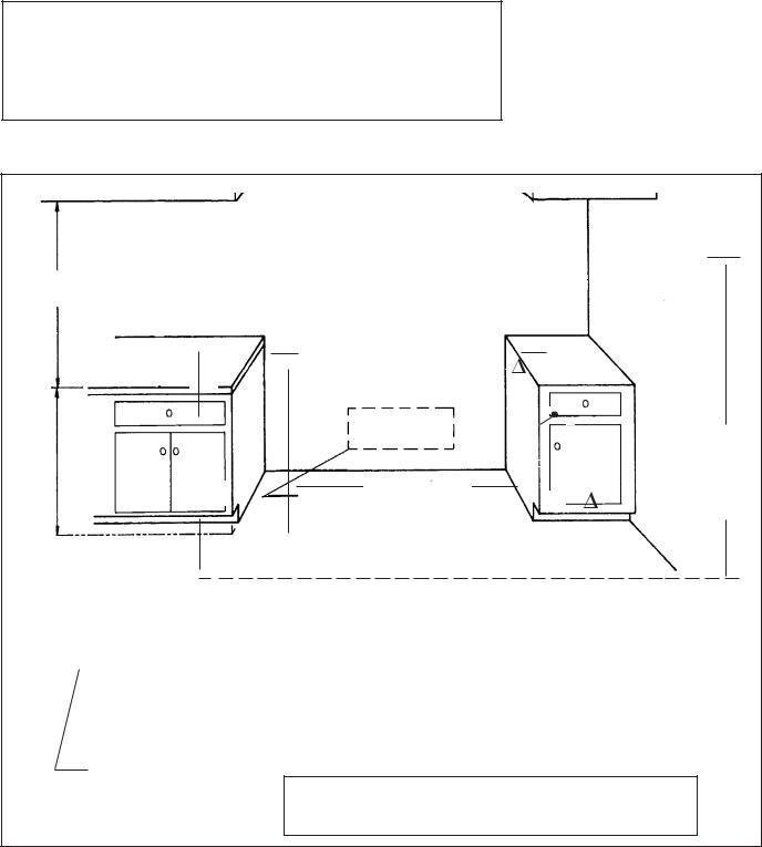
1.The range is a free standing unit. If the unit is to be placedadjacenttocabinets,theclearancesshown in Fig. 1 are required. The same clearances apply to island installations, except for the overhead cabinets, which must have a space wide enough to accept the flared island hood, as indicated in Fig. 1.
2.The 36" ranges may be recessed into the cabinets beyond the edge of the front face of the oven (See Figures 2A and 2B). The 30" and 48" ranges are not approved to be installed flush with the cabinets.
CAUTION
In these installations, the door and cabinet on 36-inch models can cause a pinching hazard.
3.The gas and electrical supply should be within the zones shown in Fig. 3A.
NOTE: The maximum depth of overhead cabinets installed on either side of the hood is 13".
A 36-inch minimum clearance is required between the top of the cooking surface and the bottom of an unprotected cabinet. It is recommended that the bottom of the wood or metal cabinet be protected by not less than 1/4 inch of a flame retardant material covered with not less than No. 28 MSG sheet steel, 0.015 inch (0.38 mm) thick stainless steel, 0.024 inch (0.6 mm) aluminum, or 0.02 inch (0.5 mm) thick copper. Flame retardant materials bear the following mark:
UNDERWRITERS LABORATORIES INC. CLASSIFIED MINERAL AND FIBER BOARDS SURFACE BURNING CHARACTERISTICS
Followed by the flame spread and smoke ratings. These designations are shown as “FHC (FIame Spread/Smoke Developed).” Materials with “O” flame spread ratings are flame retardant. Local codes may allow other flame spread ratings.
4.Any openings in the wall behind the range and in the floor under the range must be sealed.
5.When there is less than a 12" horizontal clearance between combustible material  and the back edge of the range above the cooking surface, a Thermador Low Back or Pot and Pan
Shelf backguard must be installed. (See Fig. 2A). When clearance to combustible material  is over 12", a Thermador Island Trim may be used. (See Fig. 2B). Figures 2A and 2B indicate the space required for each type of backguard.
6.A three (3) inch minimum clearance is needed when the range is installed beside a combustible side wall.
7.Always keep appliance area clear and free from combustible materials, gasoline and other flammable vapors and liquids.
8.Do not obstruct the flow of combustion and ventilation air to the unit.
As defined in the “National Fuel Gas Code” (ANSI Z223.1, Current Edition).
3
Step 2: Cabinet Preparation
CAUTION:
Do not install the 30" and 48" ranges such that the oven door is flush with the cabinet face. A flush installation could result in damage to the cabinets due to exposure to high heat.
FIG. 1 Cabinet Clearances
For 30" Ranges
For 36" Ranges
For 48" Ranges
} } }
30" or 36" Wide Hood 36" or 42" for Island
36" or 42" Wide Hood 42" or 48" for Island
48", 54, or 60" Wide Hood 48" or 54" for Island
18" Min.
➤
|
|
36"bottomofoverhead Hood to cooking surface (36" min. if hood contains combustible materials  .)
.)

|
Min. Distance Between Overhead |
|
|
|
|
|
|
|
|
|
|||||||
|
|
|
|
|
|
|
|
|
|||||||||
|
Cabinets of Combustible Material |
|
|
|
|
|
|
|
|
|
|
|
|
||||
|
|
|
30" Range – 30" |
|
|
|
|
|
|
|
|
|
|
|
|
|
|
|
|
|
36" Range – 36" |
13" Max. |
|
|
|
|
|
|
|
|
|||||
|
|
|
|
|
|
|
|
|
|
|
|
|
|
|
|
||
|
|
|
48" Range – 48" |
CabinetDepth |
} |
|
|
|
|
|
|
|
|||||
|
|
|
|
|
|
|
|
|
|||||||||
|
|
|
|
|
|
|
|
|
|
|
|
|
|
||||
|
|
|
|
|
|
|
|
|
|
|
|
|
|
||||
|
|
|
|
Range width |
3" Min. to |
|
|
||||||||||
|
|
|
|
|
|
|
|
|
|
||||||||
|
|
|
|
|
|
|
|
combustible |
|||||||||
|
|
|
|
|
|
|
|
||||||||||
|
|
|
|
|
|
side |
|
|
|
wall |
|||||||
|
|
30", 36" or 48" |
|
|
|
|
|||||||||||
|
|
|
|
|
|
|
|||||||||||
|
|
|
|
|
|
material |
, |
|
|||||||||
|
|
|
|
|
|||||||||||||
|
|
|
|
|
|
|
|
(both |
sides) |
|
|
||||||
|
|
|
|
|
|
|
|
|
|
|
|
|
|
|
|
|
|
Cooking
Surface
CAUTION: See Figs. 2A, and 2B. 36" Min. to combustible material  , from cooking surface
•
*35-3/8" Min. Range Height with Leveling Legs fully retracted
*36-3/4" Max. Range Height with Leveling Legs fully extended.
For Electrical and Gas Supply Zone, see Figure 3A. Zone size and position differ according to the model.
 as defined in the “National Fuel Gas Code” (ANSI Z223.1, Current Edition). *The range height is adjustable. The level of the range top must be at the same level or above the countertop level.
4

Step 2: Cabinet Preparation
FIG. 2A - Side View
Pot and
Pan
Shelf
3/8"
FIG. 2B - Side View
with Island Trim
4"

NOTE:
For Island Trim installations, counter surface should have a cantilever edge meeting the back section of the island trim accessory.

 Cantilever Countertop
NOTE:
If an inner wall is used under the cantilever counter top, there should be a 1/8" gap from the rear of the range to the inner wall.
5
Step 2: Cabinet Preparation
GAS AND ELECTRIC SUPPLY ZONES:
FIG. 3A Gas & Electrical Supply Zone for Dual Fuel Ranges
Typical placement shown. Otherplacement of Gas Supply and Electrical R e c e p t a c l e within the Electrical and Gas Supply Zone is acceptable.
NOTE:
If not already present, install gas shut-off valve in an easily accessible location. Make sure all users know where and how to shut off the gas supply to the range.
NOTE: The installer should inform the consumer of the location of the gas shut-off valve.
3/4" Flex Line to Appliance
Gas |
|
|
1/2" |
|
|
|
|
|
|
Supply |
|
240 VAC Receptacle |
|||||||
|
NPT |
||||||||
Zone |
|
|
|||||||
|
|
|
(Shown) or Junction |
||||||
|
|
|
|
|
|||||
|
|
|
|
|
Box |
Centerline of |
|||
A |
|
|
|
|
|||||
|
|
|
|
Electrical |
|||||
|
|
|
|
|
|||||
|
|
|
|
|
|||||
|
|
|
|
|
Supply Zone |
||||
|
|
|
|
B |
|
|
|
|
|
2" Maximum Protru- |
|
|
|
|
|
|
|||
|
|
|
|
|
|
||||
sion from Wall for |
|
|
|
E |
|
D |
|||
Gas Supply |
|
|
|
|
|||||
|
|
|
|
|
|
||||
|
|
|
|
|
|
|
|||
|
|
|
|
|
Floor |
|
|
|
|
|
|
|
|
|
|
C |
|
||
|
|
|
|
|
|
|
|
|
|
|
|
|
|
|
|
|
|
|
|
Model |
A |
B |
C |
D |
E |
|
|
|
|
|
|
30" |
8" |
12" |
10" |
6-1/2" |
5-1/4" |
36" |
10-1/2" |
15" |
10-1/2" |
6-1/2" |
5-1/4" |
|
|
|
|
|
|
48" |
16-1/2" |
16" |
15-1/2" |
6-1/2" |
5-1/4" |
|
|
|
|
|
|
NOTE: Any opening in the wall behind the appliance and any opening in the floor under the appliance must be sealed.
The Dual Fuel ranges may be connected to the power supply with a range supply cord kit or by hard-wiring to the power supply. It is the responsibility of the installer to provide the proper wiring components (cord or conduit and wires) and complete the electrical connection as dictated by local codes and ordinances, and/ or the National Electric Code. The units must be properly grounded. Refer to Step 6 for details.
The range must be connected only to the type of gas for which it is certified. If the range is to be connected to propane gas, ensure that the propane gas supply tank is equipped with its own high pressure regulator in addition to the pressure regulator supplied with the range. (See Step 5.)
6
Step 2: Cabinet Preparation
ELECTRICAL SUPPLY
Installation of the range must be planned so that the rough-in of the junction box for the receptacle or conduit connection will allow maximum clearance to the rear of the unit.
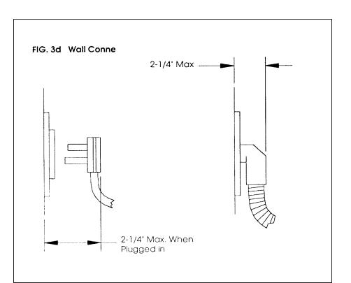
When the power supply cord (not supplied) or conduit is connected to the mating receptacle or junction box cover, the combined plug/receptacle or junction box cover/conduit connector should protrude no more than 2-1/4" from the rear wall. See Figure 3B.
This is especially critical if the junction box in the wall will be directly behind the junction box on the unit when the unit is installed. Refer to Figure 8 on Page 14 for location of junction box on unit. To minimize binding when the unit is connected to the receptacle or junction box, orient the receptacle or conduit connector, and slide back into position.
FIG. 3B WALL CONNECTION
|
|
Junction Box & Conduit |
Power Cord & Receptacle |
||
7
Step 3: Unpacking, Moving and Placing The Range
CAUTION
Proper equipment and adequate manpower must be used in moving the range to avoid injury, and to avoid damage to the unit or the floor. The unit is heavy and should be handled accordingly.
Chart A |
30" Range |
36" Range |
48" Range |
|
|
|
|
Shipping Weight |
335 lbs. |
444 lbs. |
584 lbs. |
Weight without |
285 lbs. |
390 lbs. |
524 lbs. |
packing materials |
|
|
|
Without door(s), |
215 lbs. |
295 lbs. |
395 lbs. |
burner caps, front kick |
|
|
|
panel and oven racks |
|
|
|
|
|
|
|
•The range has an approximate shipping weight as shown in ChartA.Thegrates,griddleplate and frame, burner caps, front kick panel and oven racks must be removed to facilitate handling.Thiswillreducetheweight as shown in Chart A and allow the range to pass through 30" doorways. See Figs. 2A and 2B on Page 5. Do not remove the grill or griddle assemblies.
•Remove the outer carton and packing material from the shipping base. The dual fuel ranges are held to the skid by four (4) bolts (see Fig. 4 and 5). After removing the bolts the range mustbeliftedandremovedfrom the skid.
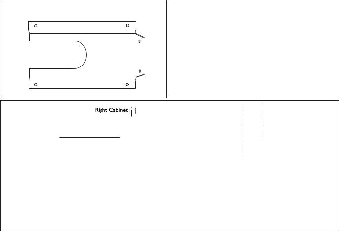
•Removeangle-mountingbrack- ets from range. This requires the installer to remove two screws holding each bracket then remove bracket and reinstall screws.
NOTE: Leave adhesive-backed foam layer over brushed-metal surfaces, to protect finish from scratches, until the range is installed in final position.
FIG. 4 – Removal of Two |
FIG. 5 – Removal of Two |
|
Front Shipping Bolts |
Rear Shipping Bolts |
|
|
Left Rear |
|
|
|
|
|
Shipping |
|
|
Bolt |
|
IMPORTANT: Do not lift the range by the oven door's handle, as this may damage the door hinges and cause the door to fit incorrectly to the oven cavity.
8

Step 3: Unpacking, Moving and Placing The Range
•Due to the weight, a dolly with soft wheels should be used to move this unit. The weight mustbesupporteduniformlyacrossthebottom
(See Fig. 6).
•After transporting the professional range by dolly close to its final location, the range can be tipped back and supported on the rear legs while the dolly is carefully removed. THE
FLOOR UNDER THE LEGS SHOULD BE PROTECTED BEFORE PUSHING THE UNIT INTO POSITION. The anti-tip device must be installed (Step 4), gas and electrical connections should be made (Steps 5 and 6), and the backguard installed (Step 7) before the range is placed in its final position.
•For proper performance the range must be level. (It is very important for all products that have the griddle feature). The range is leveled by adjusting the legs with a wrench.
•Replace the kick panel and install the oven door. To install door, see Page 17. Do not install the oven door until the range is in its final location. It is important that the two (2) screws retaining the kick panel are secure to prevent accidental access to hot surfaces.
•Ensure that the burner caps are correctly seated on the burner bases of the range's cooktop.
FIG. 6- Dolly Positioning
Remove all tape and packaging before using the appliance. Destroy the packaging after unpackingtheappliance.Neverallowchildrentoplaywith packaging material.
Grill / Griddle Tilt Adjustment (Not on all models)
Check the griddle adjustment by pouring two tablespoons of water on the back of the griddle plate. The water should slowly roll into the grease tray. If not, adjust the two screws under the back of the griddle. Start with one half turn counter clockwise (CCW) of the screws. Further adjustment should be made by one-quarter turn until water slowly flows into the grease tray.
9
Step 4: Installing Anti-Tip Device
For all 30" and 36" ranges, an anti-tip device must be installed as per these instructions.
WARNING
RANGE TIPPING HAZARD
•All ranges can tip and injury can result. To prevent accidental tipping of the range, attach it to the floor, wall or cabinet by installing the Anti-Tip Device supplied.
•A risk of tip-over may exist if the appliance is not installed in accordance with these instructions.
•If the range is pulled away from the wall for cleaning, service or any other reason, ensure that the Anti-Tip Device is properly reengaged when the range is pushed back against the wall. In the event of abnormal usage (such as a person standing, sitting, or leaning on an open door), failure to take this precaution can result in tipping of the range. Personal injury might result from spilled hot liquids or from the range itself.
 WARNING
•ALL RANGES CAN TIP
•INJURY TO PERSONS COULD RESULT
•INSTALL ANTI-TIP DEVICES PACKED WITH RANGE
•SEE INSTALLATION INSTRUCTIONS
WARNING
ELECTRICAL SHOCK HAZARD
•Use extreme caution when drilling holes into the wall or floor. There may be concealed electrical wires located behind the wall or under the floor.
•Identify the electrical circuits that could be affected by the installation of the Anti-Tip Device, then turn off power to these circuits.
•Failure to follow these instructions may result in electrical shock or other personal injury.
ATTENTION
PROPERTY DAMAGE
•Contact a qualified installer or contractor to determine the proper method for drilling holes through the wall or floor material (such as ceramic tile, hardwood, etc.)
•Do not slide the range across an unprotected floor.
•Failure to follow these instructions may result in damage to wall or floor coverings.
Tools Needed for Installation of Anti-Tip Device:
• Screwdriver, Phillips |
• Hammer |
• Drill, electric or hand |
• Pencil or other marker |
•Measuring tape or ruler
•1/8" drill bit (wood or metal wall or floor)
•3/16" carbide-tipped masonry drill bit (concrete or concrete block wall or floor)
•3/16" anchors, drywall or concrete, 4 (not required if mounting bracket is being attached to solid wood or metal)
10
Step 4: Installing Anti-Tip Device
30 and 36 Inch Ranges (Figures 7A and 7B)
Thermador Service Part No. |
Qty |
Description |
415078 |
4 |
Screw, Phillips, #10 x 1-1/2" |
487310 |
1 |
Anti-Tip Bracket, Floor-Mounted |
IMPORTANT INSTALLATION INFORMATION:
•The anti-tip bracket may be attached to a solid wood cabinet having a minimum wall thickness of 3/4".
•The thickness of the wall or floor may require use of longer screws, available at your local hardware store.
•In all cases, at least two (2) of the bracket mounting screws must be fastened to solid wood or metal.
•Use appropriate anchors when fastening the mounting bracket to any material other than hardwood or metal.
•Prepare holes at fastener locations as identified below:
-For walls, wall studs, or floors composed of solid wood or metal, drill 1/8" pilot holes.
FIG. 7A - Mounting Anti-tip Bracket
-For walls or floors composed of drywall, sheet-rock or other soft materials, drill 3/16" holes to a minimum depth of 1-3/4", then tap plastic anchors into each of the holes using a hammer.
-For walls or floors composed of concrete or concrete block, drill 3/16" holes to a minimum depth of 1-3/4", then tap concrete anchors into each of the holes using a hammer.
-For walls or floors having ceramic tile covering, drill 3/16" holes through the tile only, then drill into the material behind the tile as indicated immediately above.
•If the range is moved to a new location, the AntiTip Device must be removed and reinstalled.
MOUNTING ANTI-TIP BRACKET
The alternative floor mounted bracket shall be installed as follows:
a)Place bracket on floor in position shown in Figure 7B.
b)Secure to floor or wall stud.
c)Later, when the unit is installed, the adjustable leg will slide under the bracket.
FIG. 7B
2-1/2"
from edge of range
2-1/2"
(typical - either side)
11
Step 5: Gas Requirements and Hookup
Verify the type of gas being used at the installation site.
The appliance is shipped from the factory for use with natural gas. It must be converted for use with propane. A qualified technician or installer must do the conversion. Make certain the range matches the type of gas available at this location.
The field conversion kit for this series of dual-fuel ranges is Thermador Model PLPKIT. Obey all instructions in PLPKIT for correct conversion of the gas regulator and settings for the gas valves.
 CAUTION
When connecting unit to propane gas, make certain the propane gas tank is equipped with its own high pressure regulator in addition to the pressure regulator supplied with the appliance. The pressure of the gas supplied to the appliance regulator must not exceed 14" (34.9 mb) water column.
This appliance has been CSA certified for safe operation up to an elevation of 10,200 ft. without any modifications. Exception: For use with propane, the appliance must be converted per the LP conversion instructions.
Natural Gas Requirements:
Inlet Connection: 3/4" NPT external 1/2" NPT internal
(Minimum 3/4" diam. flex line.) Supply Pressure: 6" min. to 14" max. water col-
umn.
(14.9 to 34.9 mb) Manifold Pressure: 5" water column (12.5 mb)
Propane Gas Requirements:
Inlet Connection: 3/4" NPT external 1/2" NPT internal
(Minimum 3/4" diam. flex line.)
Supply Pressure: 11" min. to 14" max. water column.
(27.4 mb to 34.9 mb)
Manifold Pressure: 10" water column (24.9 mb)
WARNING
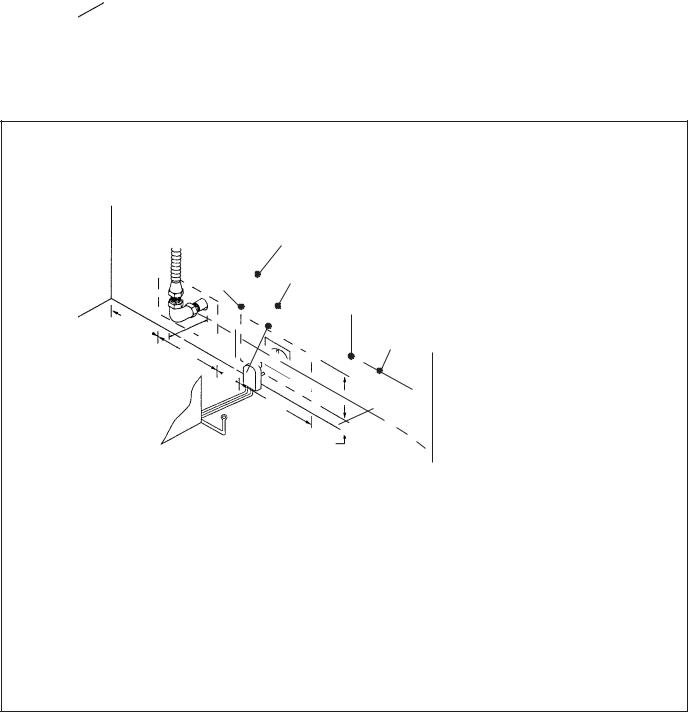
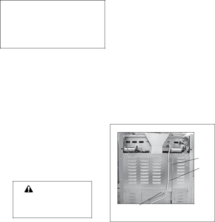
Gas line must not come in contact with any components inside back cover of range. Run gas line in channel in back of range.
HOOK UP
•A manual gas shut-off valve must be installed external to the appliance, in a location accessible from the front, for the purpose of shutting off the gas supply. The supply line must not interfere with the back of the unit. Make sure the gas supply is turned off at the manual shut-off valve before connecting the appliance.
•The range is supplied with its own pressure regulator that has been permanently mounted within the range body.
•Use 3/4" flex line to connect between the gas supply and the appliance manifold pipe, which exits the upper rear of the appliance. The appliance manifold pipe connection has a 3/4" NPT external thread and a 1/2" NPT internal thread. (See Photo A.) Use caution to avoid crimping the 3/4" flex line when making bends.
•The gas supply connections shall be made by a competent technician and in accordance with local codes or ordinances. In the absence of a local code, the installation must conform to the National Fuel Gas Code ANSI Z223.1/NFPA54current issue.
•Always use pipe sealing compound or Teflon® tape on the pipe threads, and be careful not to apply excessive pressure when tightening the fittings.
•Leak testing of the appliance shall be in accordance with the following instructions.
•Turn on gas and check supply line connections for leaks using a soap and water solution.
•Bubbles forming indicate a gas leak. Repair all leaks immediately after finding them.
•Do not use a flame of any kind to check for gas leaks.
Photo A
Channel for gas line
Use 3/4" flex line to connect between the gas supply and the appliance manifold pipe, which exits the upper rear of the appliance.
12
 Loading...