


Thermador CHMHP48XTW, DC48TW, DC486W, DC426W, DC366W User Manual
...
Installation
INSTRUCTIONS
For Pro Hood Duct Cover Extensions and Telescoping Extensions
THERMADOR.COM

Installation
INSTRUCTIONS
For Pro Hood Duct Cover Extensions and Telescoping Extensions
Table of Contents (English)................................................................ |
3 |
Table de Matières (Français) .............................................................. |
7 |
Índice de Materias (Español)............................................................ |
11 |
Models |
Modèles |
Modelos:
CHMHP366W
CHMHP36TW
CHMHP36XTW
CHMHP486W
CHMHP48TW
CHMHP48XTW
DC306W
DC366W
DC426W
DC486W
DC36TW
DC48TW
THERMADOR.COM
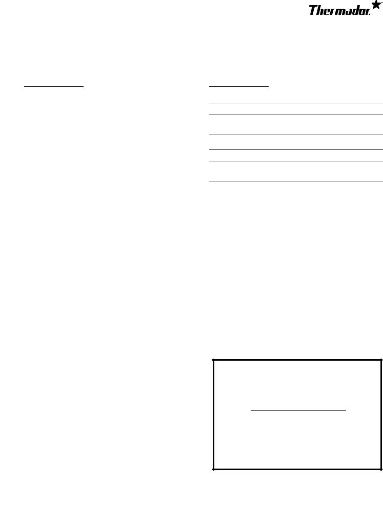
Table of
CONTENTS
Installation Instructions ........................................................... |
4 |
Before You Begin ............................................................ |
4 |
Duct Cover Extension Installation ................................... |
4 |
Telescoping Extension Installation .................................. |
5 |
Support, Accessories & Parts................................... |
back page |
Safety
DEFINITIONS
WARNING
This indicates that death or serious injuries may occur as a result of non-observance of this warning.
CAUTION
This indicates that minor or moderate injuries may occur as a result of non-observance of this warning.
NOTICE: This indicates that damage to the appliance or property may occur as a result of non-compliance with this advisory.
Note: This alerts you to important information and/or tips.
This THERMADOR® appliance is made by
BSH Home Appliances Corporation
1901 Main Street, Suite 600
Irvine, CA 92614
Questions?
1-800-735-4328 www.thermador.com
We look forward to hearing from you!
Page. 3
Installation Instructions
Before You Begin
State of California Proposition 65 Warning:
WARNING
This product can expose you to chemicals including vinyl chloride, which is known to the State of California to cause cancer and birth defects or other reproductive harm. For more information go to www.P65Warnings.ca.gov.
CAUTION
Before installing, turn power OFF at the service panel. Lock service panel to prevent power from being turned ON accidentally.
Before you begin read these instructions carefully.
Duct Cover Extensions fill the space between the hood and ceiling of 8' (2.4 m) and 9' (2.7 m) ceilings. Telescoping extensions accommodate 10' (3 m) ceilings.
Pro Hood Duct Cover Extensions
Model |
6'' Extension |
|
|
HPCN36WS |
CHMHP366W |
|
|
HPCN48WS |
CHMHP486W |
|
|
PH30HWS |
DC306W |
|
|
PH36HWS, PH36GWS |
DC366W |
|
|
PH42GWS |
DC426W |
|
|
PH48HWS, PH48GWS |
DC486W |
|
|
PH54GWS |
|
|
|
PH60GWS |
|
|
|
Pro Hood Telescoping Duct Cover Extensions
Model |
Telescoping Extension |
|
|
HPCN36WS |
CHMHP36TW |
|
|
HPCN36WS |
CHMHP36XTW |
|
|
HPCN48WS |
CHMHP48TW |
|
|
HPCN48WS |
CHMHP48XTW |
|
|
Duct Cover Extension
Installation
IMPORTANT: Secure the Hood to the wall before installing the Duct Cover Extension. Follow the Hood’s Installation Instructions before securing the Extension.
The Duct Cover Extension is supported by the hood.
1.Installation of the hood should maintain a minimum height of 30" (762 mm) from the bottom of the hood to the cooking surface. To determine placement of the hood with a Duct Cover Extension, the height of the Extension must be calculated (see the Hood’s Installation Instructions).
2.From inside of hood, screw the supplied 5/8'' (16 mm) sheet metal screws through the holes on each side and along the front into bottom of the Duct Cover Extension, as shown in below. (Screw quantity is dependent on hood size.)
1
Page. 4
Telescoping Extension
Installation
IMPORTANT: Secure the Hood to the wall after installing the Extension Mounting Bracket, but before installing the Telescoping Chimney Extension. Follow the Hood’s Installation Instructions before securing the Extension.
Securing the Telescoping Extension Bracket
1.Ensure that the minimum height of 30" (762 mm) from the bottom of the hood to the cooking surface will be maintained (see the Hood’s Installation Instructions).
2.Locate two studs at the mounting location.
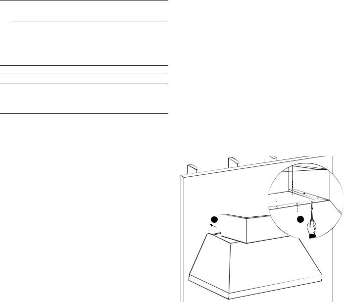
18" – 35" ( 457 – 889)
|
|
inches (mm) |
|
|
|
Model |
A |
B |
|
|
|
36'' |
14'' (356) |
20¾'' (527) |
|
|
|
48'' |
14'' (356) |
32-7/8'' (835) |
|
|
|
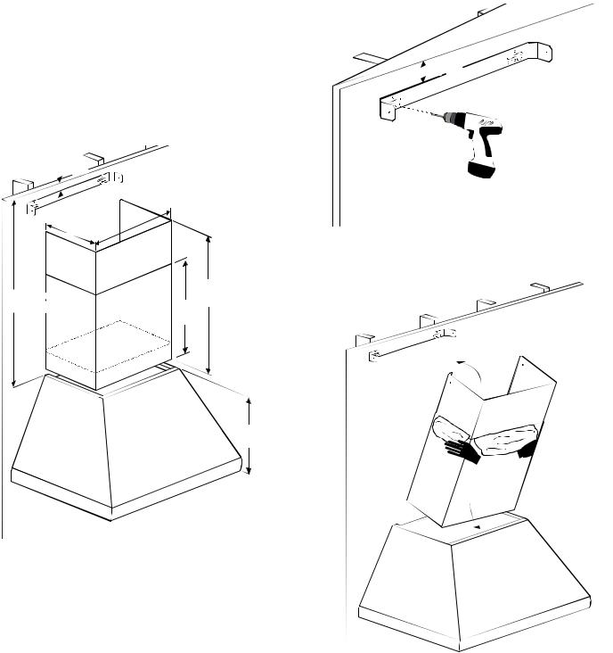
3.At the wall stud locations, measure 3½'' (89 mm) down from the ceiling to the top of the bracket.
4.Mount the bracket at the wall stud locations using (2) 1½'' (38 mm) screws (provided). Ensure that the bracket is level.
3½" (89)
inches (mm)
5.Insert the complete duct cover at an angle and swivel toward the wall.
Page. 5
 Loading...