


 Loading...
XIO3130
Data Manual
PRODUCTION DATA information is current as of publication date. Products conform to specifications per the terms of the Texas Instruments standard warranty. Production processing does not necessarily include testing of all parameters.
Literature Number: SLLS693E
May 2007–Revised April 2009

XIO3130
SLLS693E–MAY 2007–REVISED APRIL 2009 www.ti.com
|
|
|
Contents |
|
1 |
Features............................................................................................................................ |
|
11 |
|
2 |
Introduction ....................................................................................................................... |
|
12 |
|
|
2.1 |
Description .................................................................................................................. |
12 |
|
|
2.2 |
Related Documents ........................................................................................................ |
12 |
|
|
2.3 |
Document Conventions.................................................................................................... |
13 |
|
|
2.4 |
Ordering Information ...................................................................................................... |
13 |
|
|
2.5 |
Terminal Assignments ..................................................................................................... |
14 |
|
|
2.6 |
Terminal Descriptions...................................................................................................... |
17 |
|
3 |
Description ........................................................................................................................ |
|
22 |
|
|
3.1 |
Power-Up/Power-Down Sequencing..................................................................................... |
22 |
|
|
|
3.1.1 |
Power-Up Sequence ............................................................................................ |
22 |
|
|
3.1.2 |
Power-Down Sequence......................................................................................... |
23 |
|
3.2 |
Express Interface........................................................................................................... |
23 |
|
|
|
3.2.1 |
External Reference Clock ...................................................................................... |
23 |
|
|
3.2.2 |
Clock Generator ................................................................................................. |
23 |
|
|
3.2.3 |
Beacon............................................................................................................ |
24 |
|
|
3.2.4 |
WAKE ............................................................................................................ |
24 |
|
|
3.2.5 |
Initial Flow Control Credits ..................................................................................... |
24 |
|
|
3.2.6 |
PCI Express Message Transactions .......................................................................... |
24 |
|
3.3 |
GPIO Terminals ............................................................................................................ |
25 |
|
|
3.4 |
Serial EEPROM ............................................................................................................ |
25 |
|
|
|
3.4.1 |
Serial Bus Interface Implementation .......................................................................... |
26 |
|
|
3.4.2 |
Serial Bus Interface Protocol................................................................................... |
26 |
|
|
3.4.3 |
Serial Bus EEPROM Application .............................................................................. |
28 |
|
|
3.4.4 |
Accessing Serial Bus Devices Through Software........................................................... |
31 |
|
3.5 |
Switch Reset Features..................................................................................................... |
31 |
|
4 |
XIO3130 Configuration Register Space ................................................................................. |
33 |
||
|
4.1 |
PCI Configuration Register Space Overview ........................................................................... |
33 |
|
|
4.2 |
PCI Express Upstream Port Registers .................................................................................. |
34 |
|
|
|
4.2.1 |
PCI Configuration Space (Upstream Port) Register Map .................................................. |
35 |
|
|
4.2.2 |
Vendor ID Register .............................................................................................. |
36 |
|
|
4.2.3 |
Device ID Register .............................................................................................. |
36 |
|
|
4.2.4 |
Command Registers ............................................................................................ |
36 |
|
|
4.2.5 |
Status Register .................................................................................................. |
37 |
|
|
4.2.6 |
Class Code and Revision ID Register ........................................................................ |
39 |
|
|
4.2.7 |
Cache Line Size Register ...................................................................................... |
39 |
|
|
4.2.8 |
Primary Latency Timer Register ............................................................................... |
39 |
|
|
4.2.9 |
Header Type Register .......................................................................................... |
40 |
|
|
4.2.10 |
BIST Register .................................................................................................... |
40 |
|
|
4.2.11 |
Primary Bus Number............................................................................................ |
40 |
|
|
4.2.12 |
Secondary Bus Number ........................................................................................ |
40 |
|
|
4.2.13 |
Subordinate Bus Number....................................................................................... |
41 |
|
|
4.2.14 |
Secondary Latency Timer Register ........................................................................... |
41 |
|
|
4.2.15 |
I/O Base Register................................................................................................ |
41 |
|
|
4.2.16 |
I/O Limit Register ................................................................................................ |
42 |
|
|
4.2.17 |
Secondary Status Register..................................................................................... |
42 |
|
|
4.2.18 |
Memory Base Register ......................................................................................... |
43 |
|
|
4.2.19 |
Memory Limit Register .......................................................................................... |
43 |
|
|
4.2.20 |
Pre-fetchable Memory Base Register......................................................................... |
43 |
|
|
4.2.21 |
Pre-Fetchable Memory Limit Register ........................................................................ |
44 |
2 |
Contents |
Submit Documentation Feedback |

|
|
XIO3130 |
www.ti.com |
|
SLLS693E–MAY 2007–REVISED APRIL 2009 |
4.2.22 Pre-Fetchable Base Upper 32 Bits Register ................................................................. |
44 |
|
4.2.23 Pre-fetchable Limit Upper 32 Bits Register .................................................................. |
45 |
|
4.2.24 I/O Base Upper 16 Bits Register .............................................................................. |
45 |
|
4.2.25 I/O Limit Upper 16 Bits Register............................................................................... |
45 |
|
4.2.26 |
Capabilities Pointer Register................................................................................... |
45 |
4.2.27 |
Interrupt Line Register .......................................................................................... |
46 |
4.2.28 |
Interrupt Pin Register ........................................................................................... |
46 |
4.2.29 |
Bridge Control Register......................................................................................... |
46 |
4.2.30 |
Capability ID Register........................................................................................... |
48 |
4.2.31 |
Next-Item Pointer Register ..................................................................................... |
48 |
4.2.32 Power Management Capabilities Register ................................................................... |
48 |
|
4.2.33 Power Management Control/Status Register ................................................................ |
49 |
|
4.2.34 Power Management Bridge Support Extension Register .................................................. |
50 |
|
4.2.35 Power Management Data Register ........................................................................... |
50 |
|
4.2.36 MSI Capability ID Register ..................................................................................... |
50 |
|
4.2.37 |
Next-Item Pointer Register ..................................................................................... |
50 |
4.2.38 MSI Message Control Register ................................................................................ |
51 |
|
4.2.39 MSI Message Address Register ............................................................................... |
51 |
|
4.2.40 MSI Message Upper Address Register....................................................................... |
52 |
|
4.2.41 MSI Message Data Register ................................................................................... |
52 |
|
4.2.42 |
Capability ID Register........................................................................................... |
52 |
4.2.43 |
Next-Item Pointer Register ..................................................................................... |
52 |
4.2.44 Subsystem Vendor ID Register................................................................................ |
53 |
|
4.2.45 |
Subsystem ID Register ......................................................................................... |
53 |
4.2.46 PCI Express Capability ID Register ........................................................................... |
53 |
|
4.2.47 |
Next-Item Pointer Register ..................................................................................... |
54 |
4.2.48 PCI Express Capabilities Register ............................................................................ |
54 |
|
4.2.49 |
Device Capabilities Register ................................................................................... |
54 |
4.2.50 |
Device Control Register ........................................................................................ |
55 |
4.2.51 |
Device Status Register ......................................................................................... |
56 |
4.2.52 |
Link Capabilities Register ...................................................................................... |
57 |
4.2.53 |
Link Control Register............................................................................................ |
58 |
4.2.54 |
Link Status Register............................................................................................. |
59 |
4.2.55 Serial Bus Data Register ....................................................................................... |
59 |
|
4.2.56 Serial Bus Index Register ...................................................................................... |
59 |
|
4.2.57 Serial Bus Slave Address Register............................................................................ |
60 |
|
4.2.58 Serial Bus Control and Status Register ...................................................................... |
60 |
|
4.2.59 Upstream Port Link PM Latency Register.................................................................... |
61 |
|
4.2.60 Global Chip Control Register .................................................................................. |
63 |
|
4.2.61 GPIO A Control Register ....................................................................................... |
64 |
|
4.2.62 GPIO B Control Register ....................................................................................... |
66 |
|
4.2.63 GPIO C Control Register ....................................................................................... |
68 |
|
4.2.64 GPIO D Control Register ....................................................................................... |
70 |
|
4.2.65 |
GPIO Data Register ............................................................................................. |
72 |
4.2.66 |
TI Proprietary Register.......................................................................................... |
75 |
4.2.67 |
TI Proprietary Register.......................................................................................... |
75 |
4.2.68 |
TI Proprietary Register.......................................................................................... |
75 |
4.2.69 |
TI Proprietary Register.......................................................................................... |
76 |
4.2.70 |
TI Proprietary Register.......................................................................................... |
76 |
4.2.71 |
TI Proprietary Register.......................................................................................... |
76 |
4.2.72 |
Subsystem Access Register ................................................................................... |
77 |
4.2.73 |
General Control Register ....................................................................................... |
77 |
4.2.74 Downstream Ports Link PM Latency Register ............................................................... |
78 |
|
Contents 3

XIO3130
SLLS693E–MAY 2007–REVISED APRIL 2009 |
www.ti.com |
||
|
4.2.75 |
Global Switch Control Register ................................................................................ |
79 |
|
4.2.76 |
Advanced Error Reporting Capability ID Register........................................................... |
80 |
|
4.2.77 |
Next Capability Offset/Capability Version Register ......................................................... |
80 |
|
4.2.78 |
Uncorrectable Error Status Register .......................................................................... |
80 |
|
4.2.79 |
Uncorrectable Error Mask Register ........................................................................... |
81 |
|
4.2.80 |
Uncorrectable Error Severity Register ........................................................................ |
82 |
|
4.2.81 |
Correctable Error Status Register ............................................................................. |
83 |
|
4.2.82 |
Correctable Error Mask Register .............................................................................. |
84 |
|
4.2.83 |
Advanced Error Capabilities and Control Register.......................................................... |
85 |
|
4.2.84 |
Header Log Register ............................................................................................ |
85 |
4.3 |
PCI Express Downstream Port Registers............................................................................... |
86 |
|
|
4.3.1 |
PCI Configuration Space (Downstream Port) Register Map............................................... |
86 |
|
4.3.2 |
Vendor ID Register .............................................................................................. |
87 |
|
4.3.3 |
Device ID Register .............................................................................................. |
87 |
|
4.3.4 |
Command Register.............................................................................................. |
87 |
|
4.3.5 |
Status Register .................................................................................................. |
88 |
|
4.3.6 |
Class Code and Revision ID Register ........................................................................ |
89 |
|
4.3.7 |
Cache Line Size Register ...................................................................................... |
90 |
|
4.3.8 |
Primary Latency Timer Register ............................................................................... |
90 |
|
4.3.9 |
Header Type Register .......................................................................................... |
90 |
|
4.3.10 |
BIST Register .................................................................................................... |
90 |
|
4.3.11 |
Primary Bus Number............................................................................................ |
91 |
|
4.3.12 |
Secondary Bus Number ........................................................................................ |
91 |
|
4.3.13 |
Subordinate Bus Number....................................................................................... |
91 |
|
4.3.14 |
Secondary Latency Timer Register ........................................................................... |
91 |
|
4.3.15 |
I/O Base Register................................................................................................ |
92 |
|
4.3.16 |
I/O Limit Register ................................................................................................ |
92 |
|
4.3.17 |
Secondary Status Register..................................................................................... |
92 |
|
4.3.18 |
Memory Base Register ......................................................................................... |
93 |
|
4.3.19 |
Memory Limit Register .......................................................................................... |
94 |
|
4.3.20 |
Pre-fetchable Memory Base Register......................................................................... |
94 |
|
4.3.21 |
Pre-fetchable Memory Limit Register ......................................................................... |
94 |
|
4.3.22 |
Pre-fetchable Base Upper 32 Bits Register.................................................................. |
95 |
|
4.3.23 |
Pre-fetchable Limit Upper 32 Bits Register .................................................................. |
95 |
|
4.3.24 |
I/O Base Upper 16 Bits Register .............................................................................. |
96 |
|
4.3.25 |
I/O Limit Upper 16 Bits Register............................................................................... |
96 |
|
4.3.26 |
Capabilities Pointer Register................................................................................... |
96 |
|
4.3.27 |
Interrupt Line Register .......................................................................................... |
97 |
|
4.3.28 |
Interrupt Pin Register ........................................................................................... |
97 |
|
4.3.29 |
Bridge Control Register......................................................................................... |
97 |
|
4.3.30 |
Capability ID Register........................................................................................... |
99 |
|
4.3.31 |
Next-Item Pointer Register ..................................................................................... |
99 |
|
4.3.32 |
Power Management Capabilities Register ................................................................... |
99 |
|
4.3.33 |
Power Management Control/Status Register............................................................... |
100 |
|
4.3.34 |
Power Management Bridge Support Extension Register ................................................. |
101 |
|
4.3.35 |
Power Management Data Register .......................................................................... |
101 |
|
4.3.36 |
MSI Capability ID Register.................................................................................... |
101 |
|
4.3.37 |
Next-Item Pointer Register.................................................................................... |
101 |
|
4.3.38 |
MSI Message Control Register............................................................................... |
102 |
|
4.3.39 |
MSI Message Address Register ............................................................................. |
102 |
|
4.3.40 |
MSI Message Upper Address Register ..................................................................... |
103 |
|
4.3.41 |
MSI Message Data Register.................................................................................. |
103 |
|
4.3.42 |
Capability ID Register ......................................................................................... |
103 |
4 |
Contents |
Submit Documentation Feedback |

|
|
|
|
|
XIO3130 |
www.ti.com |
|
|
SLLS693E–MAY 2007–REVISED APRIL 2009 |
||
|
|
4.3.43 |
Next-Item Pointer Register.................................................................................... |
104 |
|
|
|
4.3.44 |
Subsystem Vendor ID Register .............................................................................. |
104 |
|
|
|
4.3.45 |
Subsystem ID Register........................................................................................ |
104 |
|
|
|
4.3.46 |
PCI Express Capability ID Register ......................................................................... |
104 |
|
|
|
4.3.47 |
Next-Item Pointer Register.................................................................................... |
105 |
|
|
|
4.3.48 |
PCI Express Capabilities Register........................................................................... |
105 |
|
|
|
4.3.49 |
Device Capabilities Register.................................................................................. |
105 |
|
|
|
4.3.50 |
Device Control Register ....................................................................................... |
106 |
|
|
|
4.3.51 |
Device Status Register ........................................................................................ |
107 |
|
|
|
4.3.52 |
Link Capabilities Register ..................................................................................... |
108 |
|
|
|
4.3.53 |
Link Control Register .......................................................................................... |
109 |
|
|
|
4.3.54 |
Link Status Register ........................................................................................... |
110 |
|
|
|
4.3.55 |
Slot Capabilities Register ..................................................................................... |
110 |
|
|
|
4.3.56 |
Slot Control Register .......................................................................................... |
112 |
|
|
|
4.3.57 |
Slot Status Register............................................................................................ |
114 |
|
|
|
4.3.58 |
TI Proprietary Register ........................................................................................ |
115 |
|
|
|
4.3.59 |
TI Proprietary Register ........................................................................................ |
115 |
|
|
|
4.3.60 |
TI Proprietary Register ........................................................................................ |
116 |
|
|
|
4.3.61 |
General Control Register...................................................................................... |
116 |
|
|
|
4.3.62 |
L0s Idle Timeout Register..................................................................................... |
118 |
|
|
|
4.3.63 |
General Slot Info Register .................................................................................... |
118 |
|
|
|
4.3.64 |
Advanced Error Reporting Capabilities ID Register ....................................................... |
119 |
|
|
|
4.3.65 |
Next Capability Offset/Capability Version Register........................................................ |
119 |
|
|
|
4.3.66 |
Uncorrectable Error Status Register......................................................................... |
119 |
|
|
|
4.3.67 |
Uncorrectable Error Mask Register.......................................................................... |
120 |
|
|
|
4.3.68 |
Uncorrectable Error Severity Register ...................................................................... |
121 |
|
|
|
4.3.69 |
Correctable Error Status Register ........................................................................... |
122 |
|
|
|
4.3.70 |
Correctable Error Mask Register............................................................................. |
123 |
|
|
|
4.3.71 |
Advanced Error Capabilities and Control Register ........................................................ |
123 |
|
|
|
4.3.72 |
Header Log Register .......................................................................................... |
124 |
|
5 |
PCI Hot Plug Implementation Overview ............................................................................... |
125 |
|||
|
5.1 |
PCI Hot Plug Architecture Overview ................................................................................... |
125 |
||
|
5.2 |
PCI Hot Plug Timing...................................................................................................... |
126 |
||
|
|
5.2.1 |
Power-Up Cycle ................................................................................................ |
126 |
|
|
|
|
5.2.1.1 NonPCI Hot Plug Power-Up Cycle................................................................ |
127 |
|
|
|
|
5.2.1.2 PCI Hot Plug Power-Up Cycle With PWRGDn Feedback ..................................... |
127 |
|
|
|
|
5.2.1.3 PCI Hot Plug Power-Up Cycle With No PWRGDn Feedback................................. |
127 |
|
|
|
5.2.2 |
Power-Down Cycles ........................................................................................... |
128 |
|
|
|
|
5.2.2.1 |
Normal Power-Down................................................................................ |
128 |
|
|
|
5.2.2.2 |
Surprise Removal ................................................................................... |
129 |
|
|
|
5.2.2.3 |
PWRGDn De-Assertion ............................................................................ |
129 |
|
|
5.2.3 |
PMI_Turn_Off and PME_To_Ack Messages............................................................... |
129 |
|
|
|
5.2.4 |
Debounce Circuits ............................................................................................. |
130 |
|
|
|
5.2.5 |
HP_INTX Pin ................................................................................................... |
130 |
|
6 |
Electrical Characteristics................................................................................................... |
131 |
|||
|
6.1 |
Absolute Maximum Ratings ............................................................................................. |
131 |
||
|
6.2 |
Recommended Operating Conditions.................................................................................. |
131 |
||
|
6.3 |
PCI Express Differential Transmitter Output Ranges ................................................................ |
132 |
||
|
6.4 |
PCI Express Differential Receiver Input Ranges ..................................................................... |
133 |
||
|
6.5 |
PCI Express Differential Reference Clock Input Ranges............................................................ |
134 |
||
|
6.6 |
PCI Express Reference Clock Output Requirements ................................................................ |
135 |
||
|
6.7 |
3.3-V I/O Electrical Characteristics ..................................................................................... |
136 |
||
Contents 5

XIO3130 |
|
|
SLLS693E–MAY 2007–REVISED APRIL 2009 |
www.ti.com |
|
6.8 |
POWER CONSUMPTION ............................................................................................... |
136 |
6.9 |
THERMAL CHARACTERISTICS ....................................................................................... |
136 |
6 |
Contents |
Submit Documentation Feedback |

|
|
XIO3130 |
www.ti.com |
SLLS693E–MAY 2007–REVISED APRIL 2009 |
|
|
List of Figures |
|
3-1 |
Block Diagram ..................................................................................................................... |
22 |
3-2 |
Power-Up Sequence Diagram................................................................................................... |
23 |
3-3 |
Power-Down Sequence Diagram ............................................................................................... |
23 |
3-4 |
Serial EEPROM Applications.................................................................................................... |
26 |
3-5 |
Serial-Bus Start/Stop Conditions and Bit Transfers .......................................................................... |
27 |
3-6 |
Serial-Bus Protocol Acknowledge............................................................................................... |
27 |
3-7 |
Serial-Bus Protocol – Byte Write................................................................................................ |
27 |
3-8 |
Serial-Bus Protocol – Byte Read................................................................................................ |
28 |
3-9 |
Serial-Bus Protocol – Multiple-Byte Read ..................................................................................... |
28 |
4-1 |
XIO3130 Enumerations Topology............................................................................................... |
34 |
5-1 |
NonPCI Hot Plug Power-Up Cycle ............................................................................................ |
127 |
5-2 |
PCI Hot Plug Power-Up Cycle With PWFRDn Feedback .................................................................. |
127 |
5-3 |
PCI Hot Plug Power-Up Cycle With No PWGRDn Feedback ............................................................. |
128 |
5-4 |
Normal Power-Down ............................................................................................................ |
128 |
5-5 |
Surprise Removal................................................................................................................ |
129 |
5-6 |
Effect When PWFRGn Goes Low ............................................................................................. |
129 |
List of Figures |
7 |

XIO3130
SLLS693E–MAY 2007–REVISED APRIL 2009 www.ti.com
List of Tables
2-1 |
XIO3130 Terminal Assignments ................................................................................................ |
14 |
2-2 |
XIO3130 Terminals Sorted Alphanumerically ................................................................................. |
15 |
2-3 |
XIO3130 Signal Names Sorted Alphabetically ................................................................................ |
16 |
2-4 |
Power Supply Terminals ......................................................................................................... |
17 |
2-5 |
Combined Power Terminals ..................................................................................................... |
17 |
2-6 |
Ground Terminals ................................................................................................................. |
18 |
2-7 |
PCI Express Reference Clock Terminals ...................................................................................... |
18 |
2-8 |
PCI Express Terminals ........................................................................................................... |
19 |
2-9 |
PCI Hot Plug Strapping Terminals .............................................................................................. |
19 |
2-10 |
GPIO Terminals ................................................................................................................... |
20 |
2-11 |
Miscellaneous Terminals......................................................................................................... |
21 |
3-1 |
Initial Flow Control Credit Advertisements ..................................................................................... |
24 |
3-2 |
Messages Supported by the XIO3130 ......................................................................................... |
25 |
3-3 |
EEPROM Register Loading Map................................................................................................ |
29 |
3-4 |
Register for Programming Serial-Bus Devices ................................................................................ |
31 |
3-5 |
Switch Reset Options............................................................................................................. |
32 |
4-1 |
PCI Express Upstream Port Configuration Register Map (Type 1)......................................................... |
35 |
4-2 |
Extended Configuration Space (Upstream Port).............................................................................. |
36 |
4-3 |
Bit Descriptions – Command Register ......................................................................................... |
37 |
4-4 |
Bit Descriptions – Status Register .............................................................................................. |
38 |
4-5 |
Bit Descriptions – Class Code and Revision ID Register.................................................................... |
39 |
4-6 |
Bit Descriptions – I/O Base Register ........................................................................................... |
41 |
4-7 |
Bit Descriptions – I/O Limit Register............................................................................................ |
42 |
4-8 |
Bit Descriptions – Secondary Status Register ................................................................................ |
42 |
4-9 |
Bit Descriptions – Memory Base Register ..................................................................................... |
43 |
4-10 |
Bit Descriptions – Memory Limit Register...................................................................................... |
43 |
4-11 |
Bit Descriptions – Pre-fetchable Memory Base Register .................................................................... |
43 |
4-12 |
Bit Descriptions – Pre-fetchable Memory Limit Register..................................................................... |
44 |
4-13 |
Bit Descriptions – Pre-fetchable Base Upper 32 Bits Register.............................................................. |
44 |
4-14 |
Bit Descriptions – Pre-fetchable Limit Upper 32 Bits Register .............................................................. |
45 |
4-15 |
Bit Descriptions – I/O Base Upper 16 Bits Register .......................................................................... |
45 |
4-16 |
Bit Descriptions – I/O Limit Upper 16 Bits Register .......................................................................... |
45 |
4-17 |
Bit Descriptions – Bridge Control Register..................................................................................... |
47 |
4-18 |
Bit Descriptions – Power Management Capabilities Register............................................................... |
48 |
4-19 |
Bit Descriptions – Power Management Control/Status Register............................................................ |
49 |
4-20 |
Bit Descriptions – PM Bridge Support Extension Register .................................................................. |
50 |
4-21 |
Bit Descriptions – MSI Message Control Register............................................................................ |
51 |
4-22 |
Bit Descriptions – MSI Message Address Register........................................................................... |
51 |
4-23 |
Bit Descriptions – MSI Data Register........................................................................................... |
52 |
8 |
List of Tables |
Submit Documentation Feedback |

|
|
XIO3130 |
www.ti.com |
SLLS693E–MAY 2007–REVISED APRIL 2009 |
|
4-24 |
Bit Descriptions – PCI Express Capabilities Register ........................................................................ |
54 |
4-25 |
Bit Descriptions – Device Capabilities Register............................................................................... |
55 |
4-26 |
Bit Descriptions – Device Control Register .................................................................................... |
55 |
4-27 |
Bit Descriptions – Device Status Register ..................................................................................... |
56 |
4-28 |
Bit Descriptions – Link Capabilities Register .................................................................................. |
57 |
4-29 |
Bit Descriptions – Link Control Register ....................................................................................... |
58 |
4-30 |
Bit Descriptions – Link Status Register ........................................................................................ |
59 |
4-31 |
Bit Descriptions – Serial Bus Slave Address Register ....................................................................... |
60 |
4-32 |
Bit Descriptions – Serial Bus Control and Status Register .................................................................. |
60 |
4-33 |
Bit Descriptions – Upstream Port Link PM Latency Register................................................................ |
61 |
4-34 |
Bit Descriptions – Global Chip Control Register .............................................................................. |
63 |
4-35 |
Bit Descriptions – GPIO A Control Register ................................................................................... |
65 |
4-36 |
Bit Descriptions – GPIO B Control Register ................................................................................... |
67 |
4-37 |
Bit Descriptions – GPIO C Control Register................................................................................... |
69 |
4-38 |
Bit Descriptions – GPIO D Control Register................................................................................... |
71 |
4-39 |
Bit Descriptions – GPIO Data Register......................................................................................... |
72 |
4-40 |
Bit Descriptions – Subsystem Access Register ............................................................................... |
77 |
4-41 |
Bit Descriptions – General Control Register................................................................................... |
77 |
4-42 |
Bit Descriptions – Downstream Ports Link PM Latency Register........................................................... |
78 |
4-43 |
Bit Descriptions – Global Switch Control Register............................................................................ |
79 |
4-44 |
Uncorrectable Error Status Register............................................................................................ |
80 |
4-45 |
Uncorrectable Error Mask Register ............................................................................................. |
81 |
4-46 |
Uncorrectable Error Severity Register.......................................................................................... |
82 |
4-47 |
Correctable Error Status Register............................................................................................... |
83 |
4-48 |
Correctable Error Mask Register................................................................................................ |
84 |
4-49 |
Advanced Error Capabilities and Control Register ........................................................................... |
85 |
4-50 |
PCI Express Downstream Port Configuration Register Map (Type 1) ..................................................... |
86 |
4-51 |
Extended Configuration Space (Downstream Port) .......................................................................... |
87 |
4-52 |
Bit Descriptions – Command Register ......................................................................................... |
88 |
4-53 |
Bit Descriptions – Status Register .............................................................................................. |
88 |
4-54 |
Bit Descriptions – Class Code and Revision ID Register.................................................................... |
89 |
4-55 |
Bit Descriptions – I/O Base Register ........................................................................................... |
92 |
4-56 |
Bit Descriptions – I/O Limit Register............................................................................................ |
92 |
4-57 |
Bit Descriptions – Secondary Status Register ................................................................................ |
93 |
4-58 |
IBit Descriptions – Memory Base Register .................................................................................... |
93 |
4-59 |
Bit Descriptions – Memory Limit Register...................................................................................... |
94 |
4-60 |
Descriptions – Pre-fetchable Memory Base Register ........................................................................ |
94 |
4-61 |
Bit Descriptions – Pre-fetchable Memory Limit Register..................................................................... |
95 |
4-62 |
Bit Descriptions – Pre-fetchable Base Upper 32 Bits Register.............................................................. |
95 |
4-63 |
Descriptions – Pre-fetchable Limit Upper 32 Bits Register .................................................................. |
95 |
4-64 |
Bit Descriptions – I/O Base Upper 16 Bits Register .......................................................................... |
96 |
List of Tables |
9 |

XIO3130
SLLS693E–MAY 2007–REVISED APRIL 2009 |
www.ti.com |
|
4-65 |
Bit Descriptions – I/O Limit Upper 16 Bits Register .......................................................................... |
96 |
4-66 |
Bit Descriptions – Bridge Control Register..................................................................................... |
97 |
4-67 |
Bit Descriptions – Power Management Capabilities Register............................................................... |
99 |
4-68 |
Bit Descriptions – Power Management Control/Status Register .......................................................... |
100 |
4-69 |
Bit Descriptions – PM Bridge Support Extension Register................................................................. |
101 |
4-70 |
Bit Descriptions – MSI Message Control Register .......................................................................... |
102 |
4-71 |
Bit Descriptions – MSI Message Address Register ......................................................................... |
102 |
4-72 |
Bit Descriptions – MSI Data Register ......................................................................................... |
103 |
4-73 |
Bit Descriptions – PCI Express Capabilities Register....................................................................... |
105 |
4-74 |
Bit Descriptions – Device Capabilities Register ............................................................................. |
106 |
4-75 |
Bit Descriptions – Device Control Register................................................................................... |
106 |
4-76 |
Bit Descriptions – Device Status Register.................................................................................... |
107 |
4-77 |
Bit Descriptions – Link Capabilities Register................................................................................. |
108 |
4-78 |
Bit Descriptions – Link Control Register ...................................................................................... |
109 |
4-79 |
Bit Descriptions – Link Status Register ....................................................................................... |
110 |
4-80 |
Bit Descriptions – Slot Capabilities Register ................................................................................. |
110 |
4-81 |
Bit Descriptions – Slot Control Register ...................................................................................... |
112 |
4-82 |
Bit Descriptions – Slot Status Register ....................................................................................... |
114 |
4-83 |
Bit Descriptions – General Control Register ................................................................................. |
116 |
4-84 |
Bit Descriptions – General Slot Info Register ................................................................................ |
118 |
4-85 |
Uncorrectable Error Status Register .......................................................................................... |
119 |
4-86 |
Uncorrectable Error Mask Register ........................................................................................... |
120 |
4-87 |
Uncorrectable Error Severity Register ........................................................................................ |
121 |
4-88 |
Correctable Error Status Register ............................................................................................. |
122 |
4-89 |
Correctable Error Mask Register .............................................................................................. |
123 |
4-90 |
Advanced Error Capabilities and Control Register.......................................................................... |
124 |
5-1 |
GPIO Matrix ...................................................................................................................... |
125 |
5-2 |
PCI Hot Plug Sideband Signals................................................................................................ |
126 |
5-3 |
Pins Assigned to GPIO Control Registers.................................................................................... |
126 |
10 |
List of Tables |
Submit Documentation Feedback |
www.ti.com
1 Features
∙PCI Express Base Specification, Revision 1.1
∙PCI Express Card Electromechanical Specification, Revision 1.1
∙PCI-to-PCI Bridge Architecture Specification, Revision 1.1
∙PCI Bus Power Management Interface Specification, Revision 1.2
∙PCI Express Fanout Switch With One ×1 Upstream Port and Three ×1 Downstream
Ports
∙Packet Transmission Starts While Reception Still in Progress (Cut-Through)
∙256-Byte Maximum Data Payload Size
∙Peer-to-Peer Support
XIO3130
SLLS693E–MAY 2007–REVISED APRIL 2009
∙Wake Event and Beacon Support
∙Support for D1, D2, D3hot, and D3cold
∙Active State Power Management (ASPM) Using Both L0s and L1
∙Low-Power PCI Express Transmitter Mode
∙Integrated AUX Power Switch Drains VAUX Power Only When Main Power Is Off
∙Integrated PCI Hot Plug Support
∙Integrated REFCLK Buffers for Switch Downstream Ports
∙3.3-V Multifunction I/O Pins for PCI Hot Plug Status and Control or General Purpose I/Os
∙Optional Serial EEPROM for System-Specific Configuration Register Initialization
Please be aware that an important notice concerning availability, standard warranty, and use in critical applications of Texas Instruments semiconductor products and disclaimers thereto appears at the end of this document.
PCI Express, PCI Hot Plug are trademarks of others.
PRODUCTION DATA information is current as of publication date. |
Copyright © 2007–2009, Texas Instruments Incorporated |
Products conform to specifications per the terms of the Texas |
|
Instruments standard warranty. Production processing does not |
|
necessarily include testing of all parameters. |
|

XIO3130
SLLS693E–MAY 2007–REVISED APRIL 2009 |
www.ti.com |
2 Introduction
The Texas Instruments XIO3130 switch is an integrated PCI Express fanout switch solution with one upstream x1 port and three downstream x1 ports. This high-performance integrated solution provides the latest in PCI Express switch technology including cut-through architecture, integrated reference clock buffers for downstream ports, integrated main power/VAUX power switch, and downstream port PCI Hot Plug® support.
The reader is assumed to have prior knowledge of the PCI Express interface and associated terminology and of the PCI-SIG specifications.
2.1Description
The Texas Instruments XIO3130 switch is a PCI Express ×1 3-port fanout switch. The XIO3130 provides a
single x1 upstream port supporting full 250-MB/s packet throughput in each direction simultaneously. Three independently configurable ×1 downstream ports are provided that also support full 250-MB/s packet throughput in each direction simultaneously.
A cut-through architecture is implemented to reduce the latency associated with packets moving through the PCI Express fabric. As soon as the address or routing information is decoded within the header of a packet entering an ingress port, the packet is directed to the egress port for forwarding. Packet poisoning using the EDB framing signal is supported in circumstances where packet errors are detected after the transmission of the egress packet begins.
The downstream ports may be configured to support PCI Hot Plug slot implementations. In this scenario, the system designer may decide to use the integrated PCI Hot Plug-compliant controller. This feature is available through the classic PCI configuration space under the PCI Express Capability Structure. When enabled, the downstream ports provide the PCI Hot Plug standard mechanism to apply and remove power to the slot or socket.
Power-management features include Active State Power Management, PME mechanisms, the Beacon/Wake protocol, and all conventional PCI D-states. When ASPM is enabled, each link automatically saves power when idle using the L0s and L1 states. PME messages are supported along with the PME_Turn_Off/PME_TO_Ack protocol.
When enabled, the upstream port supports Beacon transmission as well as the WAKE side band signal to wake the system as the result of a PCI Hot Plug event. Furthermore, the downstream ports may be configured to detect Beacon from downstream devices and forward this upstream. The switch also supports the translation and forwarding of WAKE from a downstream device into Beacon on the upstream port for cabled implementations.
2.2Related Documents Trademarks
PCI Express, PCI Hot Plug are trademarks of others.
12 |
Introduction |
Submit Documentation Feedback |

XIO3130
www.ti.com |
SLLS693E–MAY 2007–REVISED APRIL 2009 |
2.3Document Conventions
Throughout this data manual, several conventions are used to convey information. These conventions are listed below:
1.To identify a binary number or field, a lower case b follows the numbers. For example: 000b is a 3-bit binary field.
2.To identify a hexadecimal number or field, a lower case h follows the numbers. For example: 8AFh is a 12-bit hexadecimal field.
3.All other numbers that appear in this document that do not have either a b or h following the number are assumed to be decimal format.
4.If the signal or terminal name has a bar above the name (for example, GRST), then this indicates the logical NOT function. When asserted, this signal is a logic low, 0, or 0b.
5.Differential signal names end with P, N, +, or – designators. The P or + designators signify the positive signal associated with the differential pair. The N or – designators signify the negative signal associated with the differential pair.
6.RSVD indicates that the referenced item is reserved.
7.In Sections 4 through 6, the configuration space for the bridge is defined. For each register bit, the software-access method is identified in an access column. The legend for this access column includes the following entries:
–r – read access by software
–u – updates by the bridge internal hardware
–w – write access by software
–c – clear an asserted bit with a write-back of 1b by software. Write of zero to the field has no effect
–s – the field may be set by a write of one. Write of zero to the field has no effect.
–na – not accessible or not applicable
2.4Ordering Information
ORDERING NUMBER |
TEMPERATURE |
PACKAGE |
|
XIO3130 |
0°C to 70°C |
196-terminal ZHC |
|
XIO3130I |
–40°C to 85°C |
||
|
Submit Documentation Feedback |
Introduction |
13 |

XIO3130
SLLS693E–MAY 2007–REVISED APRIL 2009 |
www.ti.com |
2.5Terminal Assignments
The XIO3130 is packaged in a 196-ball ZHC MicroStar™ BGA.
Table 2-1. XIO3130 Terminal Assignments
|
A |
B |
C |
D |
E |
F |
G |
H |
J |
K |
L |
M |
N |
P |
|
14 |
GPIO12 |
SCL |
VDD15 |
GPIO4 |
VSSA |
DN2_ |
VSSA |
DN2_ |
DN2_ |
DN2_ |
VDD15 |
GPIO15 |
VDD15 |
VDD15 |
|
(2) |
PERn |
(2) |
Petn |
REFCKOn |
REFCKOp |
||||||||||
|
|
|
|
|
|
|
|
|
|||||||
13 |
RSVD |
GPIO13 |
VDD15 |
SDA |
VDD15 |
DN2_ |
VDD15 |
DN2_ |
VSSA |
VSSA |
DN2_ |
GPIO6 |
VDD15 |
GPIO7 |
|
PERp |
PETp |
(2) |
(2) |
DPSTRP |
|||||||||||
|
|
|
|
|
|
|
|
|
|
||||||
12 |
GPIO2 |
RSVD |
GPIO3 |
VDD33 |
VSS |
VSSA |
VDDA15 |
VSSA |
VDDA15 |
VDD33 |
GPIO5 |
VDD15 |
GPIO14 |
GPIO16 |
|
(2) |
(2) |
(2) |
(2) |
||||||||||||
|
|
|
|
|
|
|
|
|
|
|
|||||
11 |
VDD33 |
GPIO1 |
VDD15 |
VSS |
VSS |
VSSA |
VDDA15 |
VDDA15 |
VDDA15 |
VSS |
VSS |
VDD15 |
GPIO11 |
VDD33 |
|
(2) |
(2) |
(2) |
(2) |
||||||||||||
|
|
|
|
|
|
|
|
|
|
|
|||||
10 |
VSSA |
VDD15 |
DN1_ |
VSS |
VSS |
VSS |
VSS |
VSS |
VSS |
VSS |
VSS |
GPIO8 |
VDD15 |
VSSA |
|
(1) |
DPSTRP |
(3) |
|||||||||||||
|
|
|
|
|
|
|
|
|
|
|
|
||||
|
DN1_ |
DN1_ |
VSSA |
VDDA15 |
|
|
|
|
|
|
VSSA |
VSSA |
DN3_ |
DN3_ |
|
9 |
REFCK |
REFCK |
VSS |
VSS |
VSS |
VSS |
VSS |
VSS |
|||||||
(1) |
(1) |
(3) |
(3) |
PERp |
PERn |
||||||||||
|
Op |
On |
|
|
|
|
|
|
|||||||
|
|
|
|
|
|
|
|
|
|
|
|
|
|||
8 |
DN1_ |
DN1_ |
VSSA |
VDDA15 |
VSS |
VSS |
VSS |
VSS |
VSS |
VSS |
VDDA15 |
VDDA15 |
VDD15 |
VSSA |
|
PETp |
PETn |
(1) |
(1) |
(3) |
(3) |
(3) |
|||||||||
|
|
|
|
|
|
|
|
||||||||
7 |
VDDA15 |
VDD15 |
VSSA |
VDDA15 |
VSS |
VSS |
VSS |
VSS |
VSS |
VSS |
VDDA15 |
VSSA |
DN3_ |
DN3_ |
|
(1) |
(1) |
(1) |
(3) |
(3) |
PETp |
PETn |
|||||||||
|
|
|
|
|
|
|
|
||||||||
6 |
DN1_ |
DN1_ |
GPIO0 |
VSS |
VSS |
VSS |
VSS |
VSS |
VSS |
VSS |
VDDA15 |
VDDA15 |
VSSA |
DN3_ |
|
PERp |
PERn |
(3) |
(3) |
(3) |
REFCKOn |
||||||||||
|
|
|
|
|
|
|
|
|
|||||||
5 |
VSSA |
DN1_ |
VDD15 |
VSS |
VSS |
VSS |
VSS |
VSS |
VSS |
VSS |
VSS |
VSS |
VSSA |
DN3_ |
|
(1) |
PERST |
(3) |
REFCKOp |
||||||||||||
|
|
|
|
|
|
|
|
|
|
|
|||||
|
|
|
|
|
VSSA |
VDD |
VDDA15 |
VDDA15 |
VDDA15 |
|
|
|
DN3_ |
|
|
4 |
VDD15 |
VDD33 |
RSVD |
RSVD |
COMB |
VDD15 |
VSS |
VDD33 |
VDD15 |
||||||
REF |
(0) |
(0) |
(0) |
DPSTRP |
|||||||||||
|
|
|
|
|
33 |
|
|
|
|
||||||
|
|
|
|
|
|
|
|
|
|
|
|
|
|
||
3 |
VDD33 |
VDD15 |
WAKE |
VDD |
REFR1 |
VDD15 |
VSSA |
VDD15 |
VDDA33 |
VDDA15 |
GPIO18 |
GPIO17 |
GPIO9 |
VDD15 |
|
COMBIO |
REF |
(0) |
(0) |
||||||||||||
|
|
|
|
|
|
|
|
|
|
|
|||||
2 |
DN2_ |
VDD15 |
GRST |
REFR0 |
VDD33 |
VDD15 |
UP_ |
VDDA15 |
UP_ |
VSS |
UP_ |
VDD15 |
CLKREQ |
GPIO10 |
|
PERST |
REF |
PETn |
(0) |
PERn |
REFCKIn |
_UP |
|||||||||
|
|
|
|
|
|
|
|
||||||||
1 |
DN3_ |
UP_ |
VDD |
VSSD |
VAUX33 |
VDD15 |
UP_ |
VSSA |
UP_ |
VSSA |
UP_ |
VDD15 |
VDD33 |
RSVD |
|
PERST |
PERST |
COMB15 |
REF |
REF |
PETp |
(0) |
PERp |
(0) |
REFCKIp |
||||||
|
|
|
|
|
14 |
Introduction |
Submit Documentation Feedback |

|
|
|
|
|
|
|
|
|
XIO3130 |
www.ti.com |
|
|
|
|
|
SLLS693E–MAY 2007–REVISED APRIL 2009 |
|||
|
|
Table 2-2. XIO3130 Terminals Sorted Alphanumerically |
|
|
|||||
Ball |
Signal Name |
Ball |
Signal Name |
Ball |
Signal Name |
Ball |
Signal Name |
Ball |
Signal Name |
A01 |
DN3_PERST |
C13 |
VDD15 |
F11 |
VSSA(2) |
J08 |
VSS |
M06 |
VDDA15(3) |
A02 |
DN2_PERST |
C14 |
VDD15 |
F12 |
VSSA(2) |
J09 |
VSS |
M07 |
VSSA(3) |
A03 |
VDD33 |
D01 |
VSSDREF |
F13 |
DN2_PERp |
J10 |
VSS |
M08 |
VDDA15(3) |
A04 |
VDD15 |
D02 |
REFR0 |
F14 |
DN2_PERn |
J11 |
VDDA15(2) |
M09 |
VSSA(3) |
A05 |
VSSA(1) |
D03 |
VDDCOMBIO |
G01 |
UP_PETp |
J12 |
VDDA15(2) |
M10 |
GPIO8 |
A06 |
DN1_PERp |
D04 |
RSVD |
G02 |
UP_PETn |
J13 |
VSSA(2) |
M11 |
VDD15 |
A07 |
VDDA15(1) |
D05 |
VSS |
G03 |
VSSA(0) |
J14 |
DN2_REFCKOn |
M12 |
VDD15 |
A08 |
DN1_PETp |
D06 |
VSS |
G04 |
VDDA15(0) |
K01 |
VSSA(0) |
M13 |
GPIO6 |
A09 |
DN1_REFCKOp |
D07 |
VDDA15(1) |
G05 |
VSS |
K02 |
VSS |
M14 |
GPIO15 |
A10 |
VSSA(1) |
D08 |
VDDA15(1) |
G06 |
VSS |
K03 |
VDDA15(0) |
N01 |
VDD33 |
A11 |
VDD33 |
D09 |
VDDA15(1) |
G07 |
VSS |
K04 |
VDD15 |
N02 |
CLKREQ_UP |
A12 |
GPIO2 |
D10 |
VSS |
G08 |
VSS |
K05 |
VSS |
N03 |
GPIO9 |
A13 |
RSVD |
D11 |
VSS |
G09 |
VSS |
K06 |
VSS |
N04 |
DN3_DPSTRP |
A14 |
GPIO12 |
D12 |
VDD33 |
G10 |
VSS |
K07 |
VSS |
N05 |
VSSA(3) |
B01 |
UP_PERST |
D13 |
SDA |
G11 |
VDDA15(2) |
K08 |
VSS |
N06 |
VSSA(3) |
B02 |
VDD15 |
D14 |
GPIO4 |
G12 |
VDDA15(2) |
K09 |
VSS |
N07 |
DN3_PETp |
B03 |
VDD15 |
E01 |
VAUX33REF |
G13 |
VDD15 |
K10 |
VSS |
N08 |
VDD15 |
B04 |
VDD33 |
E02 |
VDD33REF |
G14 |
VSSA(2) |
K11 |
VSS |
N09 |
DN3_PERp |
B05 |
DN1_PERST |
E03 |
REFR1 |
H01 |
VSSA(0) |
K12 |
VDD33 |
N10 |
VDD15 |
B06 |
DN1_PERn |
E04 |
VSSAREF |
H02 |
VDDA15(0) |
K13 |
VSSA(2) |
N11 |
GPIO11 |
B07 |
VDD15 |
E05 |
VSS |
H03 |
VDD15 |
K14 |
DN2_REFCKOp |
N12 |
GPIO14 |
B08 |
DN1_PETn |
E06 |
VSS |
H04 |
VDDA15(0) |
L01 |
UP_REFCKIp |
N13 |
VDD15 |
B09 |
DN1_REFCKOn |
E07 |
VSS |
H05 |
VSS |
L02 |
UP_REFCKIn |
N14 |
VDD15 |
B10 |
VDD15 |
E08 |
VSS |
H06 |
VSS |
L03 |
GPIO18 |
P01 |
RSVD |
B11 |
GPIO1 |
E09 |
VSS |
H06 |
VSS |
L04 |
VSS |
P02 |
GPIO10 |
B12 |
RSVD |
E10 |
VSS |
H07 |
VSS |
L05 |
VSS |
P03 |
VDD15 |
B13 |
GPIO13 |
E11 |
VSS |
H08 |
VSS |
L06 |
VDDA15(3) |
P04 |
VDD15 |
B14 |
SCL |
E12 |
VSS |
H09 |
VSS |
L07 |
VDDA15(3) |
P05 |
DN3_REFCKOp |
C01 |
VDDCOMB15 |
E13 |
VDD15 |
H10 |
VSS |
L08 |
VDDA15(3) |
P06 |
DN3_REFCKOn |
C02 |
GRST |
E14 |
VSSA(2) |
H11 |
VDDA15(2) |
L09 |
VSSA(3) |
P07 |
DN3_PETn |
C03 |
WAKE |
F01 |
VDD15 |
H12 |
VSSA(2) |
L10 |
VSS |
P08 |
VSSA(3) |
C04 |
RSVD |
F02 |
VDD15 |
H13 |
DN2_PETp |
L11 |
VSS |
P09 |
DN3_PERn |
C05 |
VDD15 |
F03 |
VDD15REF |
H14 |
DN2_PETn |
L12 |
GPIO5 |
P10 |
VSSA(3) |
C06 |
GPIO0 |
F04 |
VDDCOMB33 |
J01 |
UP_PERp |
L13 |
DN2_DPSTRP |
P11 |
VDD33 |
C07 |
VSSA(1) |
F05 |
VSS |
J02 |
UP_PERn |
L14 |
VDD15 |
P12 |
GPIO16 |
C08 |
VSSA(1) |
F06 |
VSS |
J03 |
VDDA33 |
M01 |
VDD15 |
P13 |
GPIO7 |
C09 |
VSSA(1) |
F07 |
VSS |
J04 |
VDDA15(0) |
M02 |
VDD15 |
P14 |
VDD15 |
C10 |
DN1_DPSTRP |
F08 |
VSS |
J05 |
VSS |
M03 |
GPIO17 |
|
|
C11 |
VDD15 |
F09 |
VSS |
J06 |
VSS |
M04 |
VDD33 |
|
|
C12 |
GPIO3 |
F10 |
VSS |
J07 |
VSS |
M05 |
VSS |
|
|
Submit Documentation Feedback |
Introduction |
15 |
XIO3130
SLLS693E–MAY 2007–REVISED APRIL 2009 www.ti.com
Table 2-3. XIO3130 Signal Names Sorted Alphabetically
Signal Name |
Ball |
Signal Name |
Ball |
|
CLKREQ_UP |
N02 |
GPIO5 |
L12 |
|
DN1_DPSTRP |
C10 |
GPIO6 |
M13 |
|
DN1_PERn |
B06 |
GPIO7 |
P13 |
|
DN1_PERp |
A06 |
GPIO8 |
M10 |
|
DN1_PERST |
B05 |
GPIO9 |
N03 |
|
DN1_PETn |
B08 |
GRST |
C02 |
|
DN1_PETp |
A08 Suggested Program Value |
REFR0 |
D02 |
|
DN1_REFCKOn |
B09 |
REFR1 |
E03 |
|
DN1_REFCKOp |
A09 |
RSVD |
A13, B12, C04, D04, P01 |
|
DN2_DPSTRP |
L13 |
SCL |
B14 |
|
DN2_PERn |
F14 |
SDA |
D13 |
|
DN2_PERp |
F13 |
UP_PERn |
J02 |
|
DN2_PERST |
A02 |
UP_PERp |
J01 |
|
DN2_PETn |
H14 |
UP_PERST |
B01 |
|
DN2_PETp |
H13 |
UP_PETn |
G02 |
|
DN2_REFCKOn |
J14 |
UP_PETp |
G01 |
|
DN2_REFCKOp |
K14 |
UP_REFCKIn |
L02 |
|
DN3_DPSTRP |
N04 |
UP_REFCKIp |
L01 |
|
DN3_PERn |
P09 |
VAUX33REF |
E01 |
|
|
|
|
A04, B02, B03, B07, B10, C05, C11, C13, |
|
DN3_PERp |
N09 |
VDD15 |
C14, E13, F01, F02, G13, H03, K04, L14, |
|
M01, M02, M11, M12, N08, N10, N13, N14, |
||||
|
|
|
||
|
|
|
P03, P04, P14 |
|
DN3_PERST |
A01 |
VDDA15(0) |
G04, H02, H04, J04, K03 |
|
DN3_PETn |
P07 |
VDDA15(1) |
A07, D07, D08, D09 |
|
DN3_PETp |
N07 |
VDDA15(2) |
G11, G12, H11, J11, J12 |
|
DN3_REFCKOn |
P06 |
VDDA15(3) |
L06, L07, L08, M06, M08 |
|
DN3_REFCKOp |
P05 |
VDD15REF |
F03 |
|
GPIO0 |
C06 |
VDD33 |
A03, A11, B04, D12, K12, M04, N01, P11 |
|
GPIO1 |
B11 |
VDD33REF |
E02 |
|
GPIO10 |
P02 |
VDDA33 |
J03 |
|
GPIO11 |
N11 |
VDDCOMB15 |
C01 |
|
GPIO12 |
A14 |
VDDCOMB33 |
F04 |
|
GPIO13 |
B13 |
VDDCOMBIO |
D03 |
|
|
|
|
D05, D06, D10, D11, E05, E06, E07, E08, |
|
|
|
|
E09, E10, E11, E12, F05, F06, F07, F08, |
|
|
|
|
F09, F10, G05, G06, G07, G08, G09, G10, |
|
GPIO14 |
N12 |
VSS |
H05, H06, H07, H08, H09, H10, J05, J06, |
|
|
|
|
J07, J08, J09, J10, K02, K05, K06, K07, |
|
|
|
|
K08, K09, K10, K11, L04, L05, L10, L11, |
|
|
|
|
M05 |
|
GPIO15 |
M14 |
VSSA(0) |
G03, H01, K01 |
|
GPIO16 |
P12 |
VSSA(1) |
A05, A10, C07, C08, C09 |
|
GPIO17 |
M03 |
VSSA(2) |
E14, F11, F12, G14, H12, J13, K13 |
|
GPIO18 |
L03 |
VSSA(3) |
L09, M07, M09, N05, N06, P08, P10 |
|
GPIO2 |
A12 |
VSSAREF |
E04 |
|
GPIO3 |
C12 |
VSSDREF |
D01 |
|
GPIO4 |
D14 |
WAKE |
C03 |
16 |
Introduction |
Submit Documentation Feedback |
XIO3130
www.ti.com |
SLLS693E–MAY 2007–REVISED APRIL 2009 |
2.6Terminal Descriptions
Table 2-4. Power Supply Terminals
Signal |
Ball |
I/O Type |
External parts |
VDDA15(0) |
G04, H02, H04, J04, |
|
K03 |
||
|
||
VDDA15(1) |
A07, D07, D08, D09 |
|
VDDA15(2) |
G11, G12, H11, J11, J12 |
|
VDDA15(3) |
L06, L07, L08, M06, M08 |
|
|
A04, B02, B03, B07, |
|
|
B10, C05, C11, C13, |
|
|
C14, E13, F01, F02, |
|
VDD15 |
G13, H03, K04, L14, |
|
|
M01, M02, M11, M12, |
|
|
N08, N10, N13, N14, |
|
|
P03, P04, P14 |
PWR Filter
PWR Filter
PWR Filter
PWR Filter
PWR
Bypass capacitors
Description
1.5-V analog power terminals for PCI-Express upstream port 0
1.5-V analog power terminals for PCI-Express downstream port 1
1.5-V analog power terminals for PCI-Express downstream port 2
1.5-V analog power terminals for PCI-Express downstream port 3
1.5-V digital core power terminals
VDD33 |
A03, A11, B04, D12, |
PWR |
Bypass |
3.3-V digital I/O power terminals |
|
K12, M04, N01, P11 |
capacitors |
||||
|
|
|
|||
VDDA33 |
J03 |
PWR |
Filter |
3.3-V analog power terminal |
|
VAUX33REF |
E01 |
PWR |
Bypass |
3.3-V digital VAUX power terminal |
|
capacitors |
|||||
|
|
|
|
||
VDD15REF |
F03 |
PWR |
Filter |
1.5-V PCI-Express reference power terminal |
|
VDD33REF |
E02 |
PWR |
Filter |
3.3-V PCI-Express reference power terminal |
Table 2-5. Combined Power Terminals
Signal |
Ball |
I/O Type |
External Parts |
VDDCOMBIO |
D03 |
Passive |
Bypass capacitors |
VDDCOMB33 |
F04 |
Passive |
Bypass capacitors |
VDDCOMB15 |
C01 |
Passive |
Bypass capacitors |
Description
Internally combined 3.3-V main and VAUX power output for external bypass capacitor filtering. Supplies all internal 3.3-V input and output circuitry powered during D3 cold. Caution: Do not use this terminal to supply external power to other devices.
Internally combined 3.3-V main and VAUX power output for external bypass capacitor filtering. Supplies all internal 3.3-V circuitry powered during D3 cold. Caution: Do not use this terminal to supply external power to other devices.
Internally combined 1.5-V main and VAUX power output for external bypass capacitor filtering. Supplies all internal 1.5-V circuitry powered during D3 cold. Caution: Do not use this terminal to supply external power to other devices.
Submit Documentation Feedback |
Introduction |
17 |
XIO3130
SLLS693E–MAY 2007–REVISED APRIL 2009 www.ti.com
Table 2-6. Ground Terminals
Signal |
Ball |
I/O Type |
Description |
|
|
D05, D06, D10, D11, E05, |
|
|
|
|
E06, E07, E08, E09, E10, |
|
|
|
|
E11, E12, F05, F06, F07, |
|
|
|
|
F08, F09, F10, G05, G06, |
|
|
|
VSS |
G07, G08, G09, G10, |
GND |
Digital ground terminals |
|
H05, H06, H07, H08, H09, |
||||
|
|
|
||
|
H10, J05, J06, J07, J08, |
|
|
|
|
J09, J10, K02, K05, K06, |
|
|
|
|
K07, K08, K09, K10, K11, |
|
|
|
|
L04, L05, L10, L11, M05 |
|
|
|
VSSA(0) |
G03, H01, K01 |
GND |
Analog ground terminals for upstream Port 0 |
|
VSSA(1) |
A05, A10, C07, C08, C09 |
GND |
Analog ground terminals for downstream Port 1 |
|
VSSA(2) |
E14, F11, F12, G14, H12, |
GND |
Analog ground terminals for downstream Port 2 |
|
J13, K13 |
||||
|
|
|
||
VSSA(3) |
L09, M07, M09, N05, N06, |
GND |
Analog ground terminals for downstream Port 3 |
|
P08, P10 |
||||
|
|
|
||
VSSAREF |
E04 |
GND |
1.5-V PCI-Express analog reference ground terminal |
|
VSSDREF |
D01 |
GND |
1.5-V PCI-Express digital reference ground terminal |
Table 2-7. PCI Express Reference Clock Terminals
Signal  Ball
Ball  I/O Type
  External Parts
  Description
UP_REFCKIp |
L01 |
HS DIFF IN |
|
UP_REFCKIn |
L02 |
||
|
|||
DN1_REFCKOp |
A09 |
HS DIFF OUT |
|
DN1_REFCKOn |
B09 |
||
|
|||
DN2_REFCKOp |
K14 |
HS DIFF OUT |
|
DN2_REFCKOn |
J14 |
||
|
|||
DN3_REFCKOp |
P05 |
HS DIFF OUT |
|
DN3_REFCKOn |
P06 |
||
|
Reference clock inputs. REFCKIp and REFCKIn comprise the differential input pair for the 100-MHz system reference clock.
100 MHz differential reference clock outputs for downstream port 1
100 MHz differential reference clock outputs for downstream port 2
100 MHz differential reference clock outputs for downstream port 3
18 |
Introduction |
Submit Documentation Feedback |
www.ti.com
Signal |
Ball |
UP_PETp |
G01 |
UP_PETn |
G02 |
DN1_PETp |
A08 |
DN1_PETn |
B08 |
DN2_PETp |
H13 |
DN2_PETn |
H14 |
DN3_PETp |
N07 |
DN3_PETn |
P07 |
UP_PERp |
J01 |
UP_PERn |
J02 |
DN1_PERp |
A06 |
DN1_PERn |
B06 |
DN2_PERp |
F13 |
DN2_PERn |
F14 |
DN3_PERp |
N09 |
DN3_PERn |
P09 |
REFR0 |
D02 |
REFR1 |
E03 |
UP_PERST |
B01 |
DN1_PERST |
B05 |
DN2_PERST |
A02 |
DN3_PERST |
A01 |
WAKE |
C03 |
XIO3130
SLLS693E–MAY 2007–REVISED APRIL 2009
Table 2-8. PCI Express Terminals
I/O Type |
External Parts |
Description |
|
HS DIFF |
Series capacitors |
High-speed differential transmit pair for upstream port 0 |
|
OUT |
|||
|
|
||
HS DIFF |
Series capacitors |
High-speed differential transmit pair for downstream port 1 |
|
OUT |
|||
|
|
||
HS DIFF |
Series capacitors |
High-speed differential transmit pair for downstream port 2 |
|
OUT |
|||
|
|
||
HS DIFF |
Series capacitors |
High-speed differential transmit pair for downstream port 3 |
|
OUT |
|||
|
|
||
HS DIFF IN |
|
High-speed differential receiver pair for upstream port 0 |
|
HS DIFF IN |
|
High-speed differential receiver pair for downstream port 1 |
|
HS DIFF IN |
|
High-speed differential receiver pair for downstream port 2 |
|
HS DIFF IN |
|
High-speed differential receiver pair for downstream port 3 |
|
Passive |
External bias |
External reference resistor terminals for setting TX driver current. An |
|
resistor |
external resistor is connected between these terminals. |
||
|
|||
|
|
PCI-Express reset input. When logic high, the PERST signal |
|
LV CMOS IN |
System-side |
identifies that the system power is stable. When logic low, the |
|
pullup resistor |
PERST signal generates an internal power-on reset. |
||
|
|
Note: The UP_PERST input buffer has hysteresis. |
|
LV CMOS O |
Pulldown resistor |
PCI-Express reset output for downstream port 1. |
|
LV CMOS O |
Pulldown resistor |
PCI-Express reset output for downstream port 2. |
|
LV CMOS O |
Pulldown resistor |
PCI-Express reset output for downstream port 3. |
|
|
|
WAKE is an active low signal that is driven low to reactivate the |
|
LV CMOS I/O |
System-side |
PCI-Express link hierarchy’s main power rails and reference clocks. |
|
pullup resistor |
Note: Since WAKE is an open-drain output buffer, a system-side |
||
|
|
||
|
|
pullup resistor is required. |
Table 2-9. PCI Hot Plug Strapping Terminals
Signal |
Ball |
I/O Type |
External Parts |
Description |
|
|
|
|
Downstream Port 1 Strap. This pin is pulled high at the de-assertion of |
|
|
|
|
reset. GPIO0, GPIO1, and GPIO2 are used as PCI Hot Plug terminals |
DN1_DPSTR |
C10 |
LV CMOS IN |
Pullup or pulldown |
for downstream port 1 and are no longer available for use as GPIOs. |
P |
resistor |
The three terminals become PRESENT, PWR_ON, and PWR_GOOD |
||
|
|
|
|
respectively. These GPIOs are available for normal use if this terminal |
|
|
|
|
is pulled low at the de-assertion of reset. |
|
|
|
|
Downstream Port 2 Strap. This pin is pulled high at the de-assertion of |
|
|
|
|
reset. GPIO4, GPIO5, and GPIO6 are used as PCI Hot Plug terminals |
DN2_DPSTR |
L13 |
LV CMOS IN |
Pullup or pulldown |
for downstream port 2 and are no longer available for use as GPIOs. |
P |
resistor |
The three terminals become PRESENT, PWR_ON, and PWR_GOOD |
||
|
|
|
|
respectively. These GPIOs are available for normal use if this terminal |
|
|
|
|
is pulled low at the de-assertion of reset. |
|
|
|
|
Downstream Port 3 Strap. This pin is pulled high at the de-assertion of |
|
|
|
|
reset. GPIO8, GPIO9, and GPIO10 are used as PCI Hot Plug terminals |
DN3_DPSTR |
N04 |
LV CMOS IN |
Pullup or pulldown |
for downstream port 3 and are no longer available for use as GPIOs. |
P |
resistor |
The three terminals become PRESENT, PWR_ON, and PWR_GOOD |
respectively. These GPIOs are available for normal use if this terminal is pulled low at the de-assertion of reset.
Submit Documentation Feedback |
Introduction |
19 |

XIO3130
SLLS693E–MAY 2007–REVISED APRIL 2009 www.ti.com
Table 2-10. GPIO Terminals
Signal  Ball
Ball  I/O Type
  External Parts
  Description
GPIO0 |
C06 |
LV CMOS I/O |
GPIO1 |
B11 |
LV CMOS I/O |
GPIO2 |
A12 |
LV CMOS I/O |
GPIO 0. If the DN1_DPSTRP pin is pulled high at the de-assertion of reset, this pin functions as the PRSNT hotplug pin for downstream port 1. Otherwise this pin’s function is programmed with the GPIO A Control register.
GPIO 1. If the DN1_DPSTRP pin is pulled high at the de-assertion of reset, this pin functions as the POWERON hotplug pin for downstream port 1. Otherwise this pin’s function is programmed with the GPIO A Control register.
GPIO 2. If the DN1_DPSTRP pin is pulled high at the de-assertion of reset, this pin functions as the PWRGD hotplug pin for downstream port 1. Otherwise this pin’s function is programmed with the GPIO A Control register
GPIO3 |
C12 |
LV CMOS I/O |
GPIO4 |
D14 |
LV CMOS I/O |
GPIO5 |
L12 |
LV CMOS I/O |
GPIO6 |
M13 |
LV CMOS I/O |
GPIO7 |
P13 |
LV CMOS I/O |
GPIO8 |
M10 |
LV CMOS I/O |
GPIO9 |
N03 |
LV CMOS I/O |
GPIO10 |
P02 |
LV CMOS I/O |
GPIO11 |
N11 |
LV CMOS I/O |
GPIO12 |
A14 |
LV CMOS I/O |
GPIO13 |
B13 |
LV CMOS I/O |
GPIO14 |
N12 |
LV CMOS I/O |
GPIO15 |
M14 |
LV CMOS I/O |
GPIO16 |
P12 |
LV CMOS I/O |
GPIO17 |
M03 |
LV CMOS I/O |
GPIO18 |
L03 |
LV CMOS I/O |
GPIO 3. This pin’s function is programmed with the GPIO A Control register.
GPIO 4. If the DN2_DPSTRP pin is pulled high at the de-assertion of reset, this pin functions as the PRSNT hotplug pin for downstream port 2. Otherwise this pin’s function is programmed with the GPIO A
Control register.
GPIO 5. If the DN2_DPSTRP pin is pulled high at the de-assertion of reset, this pin functions as the POWERON hotplug pin for downstream port 2. Otherwise this pin’s function is programmed with the GPIO A Control register.
GPIO 6. If the DN2_DPSTRP pin is pulled high at the de-assertion of reset, this pin functions as the PWRGD hotplug pin for downstream port 2. Otherwise this pin’s function is programmed with the GPIO A Control register.
GPIO 7. This pin’s function is programmed with the GPIO A Control register.
GPIO 8. If the DN3_DPSTRP pin is pulled high at the de-assertion of reset, this pin functions as the PRSNT hotplug pin for downstream port 3. Otherwise this pin’s function is programmed with the GPIO B Control register.
GPIO 9. If the DN3_DPSTRP pin is pulled high at the de-assertion of reset, this pin functions as the POWERON hotplug pin for downstream port 3. Otherwise this pin’s function is programmed with the GPIO B Control register.
GPIO 10. If the DN3_DPSTRP pin is pulled high at the de-assertion of reset, this pin functions as the PWRGD hotplug pin for downstream port 3. Otherwise this pin’s function is programmed with the GPIO B Control register.
GPIO 11. This pin’s function is programmed with the GPIO B Control register.
GPIO 12. This pin’s function is programmed with the GPIO B Control register.
GPIO 13. This pin’s function is programmed with the GPIO B Control register.
GPIO 14. This pin’s function is programmed with the GPIO B Control register.
GPIO 15. This pin’s function is programmed with the GPIO B Control register.
GPIO16. This pin’s function is programmed with the GPIO C Control register.
GPIO 17. This pin’s function is programmed with the GPIO C Control register.
GPIO 18. This pin’s function is programmed with the GPIO C Control register.
20 |
Introduction |
Submit Documentation Feedback |
|
|
|
|
XIO3130 |
www.ti.com |
|
|
|
SLLS693E–MAY 2007–REVISED APRIL 2009 |
|
|
Table 2-11. Miscellaneous Terminals |
||
Signal |
Ball |
I/O Type |
External Parts |
Description |
|
C02 |
LV CMOS IN |
|
Global power-on reset input. Note: a pullup to Vaux (if supported) or |
GRST |
|
|
See description |
VDD3.3 (if not) is required unless this terminal is always driven by |
|
|
|
|
the upstream device. |
SDA |
D13 |
LV CMOS I/O |
|
Serial Data. This pin is the serial data pin for the EEPROM interface. |
SCL |
B14 |
LV CMOS O |
|
Serial Clock. This pin is the serial clock pin for the EEPROM |
|
|
|
interface. |
|
|
|
|
|
|
|
N02 |
LV CMOS O |
|
Upstream Clock Request. When asserted low, requests upstream |
CLKREQ_UP |
|
|
|
device restart clock in cases where upstream clock may be removed |
|
|
|
|
in L1 |
RSVD |
A13, B12, |
|
|
Reserved. These terminals must tied to VDD15. |
RSVD |
C04, P01 |
|
|
Reserved. This terminal must be tied to GND. |
RSVD |
D04 |
|
See description |
Reserved. Pullup to Vaux (if supported) or VDD3.3 (if not) |
Submit Documentation Feedback |
Introduction |
21 |
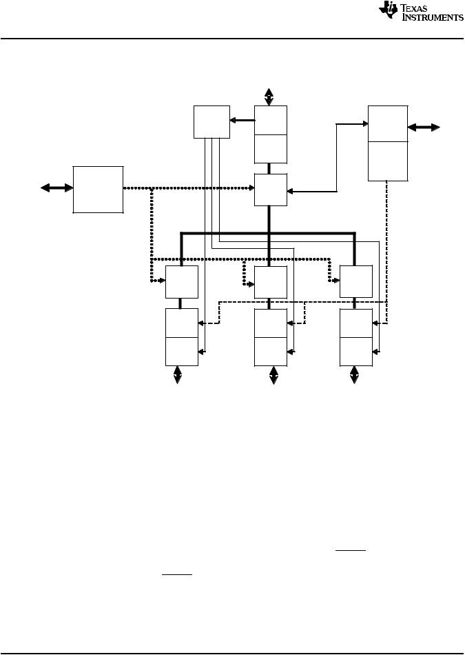
XIO3130
SLLS693E–MAY 2007–REVISED APRIL 2009 |
www.ti.com |
3 Description
Figure 3-1 is the block diagram of the XIO3130.
Clock |
PCI |
|
|
Distribution/ |
Express |
GPIO |
|
Reset Logic |
X1 Phy |
||
|
|||
|
Port 0 |
|
|
|
(Up) |
PCI Hot |
|
|
Logic |
||
|
|
Plug |
|
|
Virtual |
|
|
EEPROM |
PCI to |
|
|
PCI |
|
||
|
|
||
|
Bridge |
|
|
Virtual |
Virtual |
Virtual |
|
PCI to |
PCI to |
PCI to |
|
PCI Bridge |
PCI Bridge |
PCI Bridge |
|
Bridge |
Bridge |
Bridge |
|
Port 1 |
Port 2 |
Port 3 |
|
(Down) |
(Down) |
(down) |
|
Logic |
Logic |
logic |
|
PCI |
PCI |
PCI |
|
Express x1 |
Express x1 |
Express x1 |
|
Phy |
Phy |
Phy |
Figure 3-1. Block Diagram
3.1Power-Up/Power-Down Sequencing
The following sections describe the procedures to power up and power down the XIO3130 switch.
3.1.1Power-Up Sequence
1.Assert PERST to the device.
2.Apply 1.5-V and 3.3-V voltages in any order with any time relationship and with any ramp rate.
3.Apply a stable PCI Express reference clock.
To meet PCI Express specification requirements, PERST cannot be de-asserted until the following two delay requirements are satisfied:
∙Wait a minimum of 100 μs after applying a stable PCI Express reference clock. The 100-μs limit satisfies the requirement for stable device clocks by the de-assertion of PERST.
∙Wait a minimum of 100 ms after applying power. The 100-ms limit satisfies the requirement for stable power by the de-assertion of PERST.
See Figure 3-2, Power-Up Sequence Diagram.
22 |
Description |
Submit Documentation Feedback |
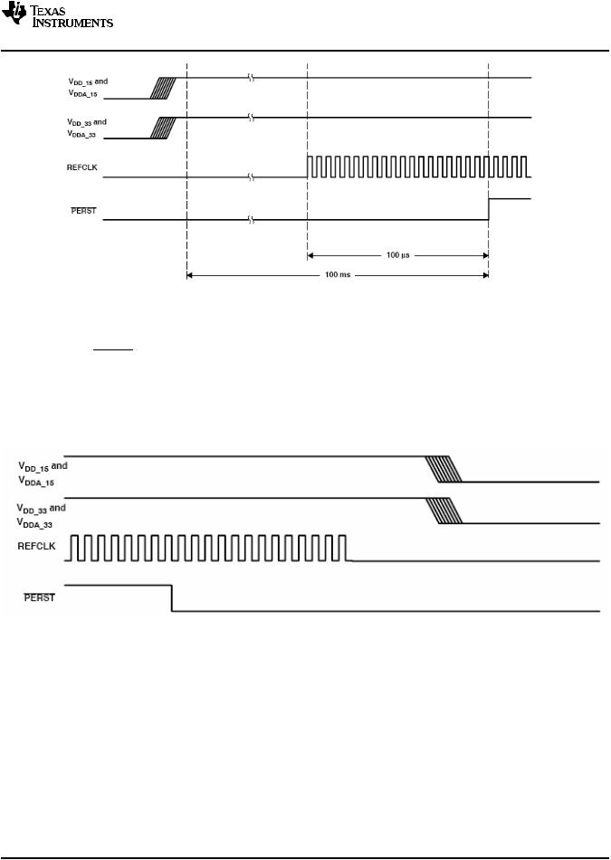
XIO3130
www.ti.com |
SLLS693E–MAY 2007–REVISED APRIL 2009 |
Figure 3-2. Power-Up Sequence Diagram
3.1.2Power-Down Sequence
∙Assert PERST to the device.
∙Remove the reference clock.
∙Remove 3.3-V and 1.5-V voltages.
See the power-down sequence diagram in Figure 3-3. If the VAUX33REF terminal is to remain powered after a system shutdown, the switch power-down sequence is exactly the same as shown in Figure 3-3.
Figure 3-3. Power-Down Sequence Diagram
3.2Express Interface
3.2.1External Reference Clock
The Texas Instruments XIO3130 switch requires a differential 100 MHz common clock reference. The clock reference must meet all PCI Express electrical specification requirements for frequency tolerance, spread spectrum clocking, and signal electrical characteristics.
3.2.2Clock Generator
The clock generator is responsible for generating all internal and external clocks from the PCI Express reference clock. This includes the PHY transmitter serial link clock, the three downstream reference clock outputs, the 60-kHz serial bus interface clock, and all internal clock domains.
Submit Documentation Feedback |
Description |
23 |

XIO3130
SLLS693E–MAY 2007–REVISED APRIL 2009 |
www.ti.com |
3.2.3Beacon
The XIO3130 supports the PCI Express in-band beacon feature. Beacon is driven on the PCI Express link by the XIO3130 to request the re-application of main power when in the L2 link state. Once beacon is activated, the XIO3130 continues to send the beacon signal until main power is restored as indicated by PERST going inactive. At this time, the beacon signal is deactivated.
3.2.4WAKE
The XIO3130 supports the PCI Express sideband WAKE feature. WAKE is an active-low signal driven by the XIO3130 to request the re-application of main power when in the L2 link state. Since WAKE is an open-collector output, a system-side pullup resistor is required to prevent the signal from floating. If WAKE to Beacon translation is enabled (see section 3.2.60), the XIO3130 detects when WAKE is asserted and transmits beacon to alert the system. This enables support for devices that use the WAKE protocol in a system that does not support it.
3.2.5Initial Flow Control Credits
The XIO3130 flow control credits are initialized using the rules defined in the PCI Express Base Specification. Table 3-1 identifies the initial flow control credit advertisement for the XIO3130. The initial advertisement is exactly the same for both upstream and downstream ports.
Table 3-1. Initial Flow Control Credit Advertisements
Credit Type |
|
Initial Advertisement |
|
Hex |
Decimal |
||
|
|||
Posted Request Headers (PH) |
10 |
16 |
|
Posted Request Data (PD) |
80 |
128 |
|
Non-Posted Header (NPH) |
10 |
16 |
|
Non-Posted Data (NPD) |
10 |
16 |
|
Completion Header (CPLH) |
10 |
16 |
|
Completion Data (CPLD) |
80 |
128 |
3.2.6PCI Express Message Transactions
PCI Express messages are initiated by, received by and passed through the XIO3130. Table 3-2 outlines message support within the switch.
24 |
Description |
Submit Documentation Feedback |

XIO3130
www.ti.com |
SLLS693E–MAY 2007–REVISED APRIL 2009 |
Table 3-2. Messages Supported by the XIO3130
Message |
Supported |
Assert_INTx |
Yes |
Deassert_INTx |
Yes |
PM_Active_State_Nak |
Yes |
PM_PME |
Yes |
PME_Turn_Off |
Yes |
PME_TO_Ack |
Yes |
ERR_COR |
Yes |
ERR_NONFATAL |
Yes |
ERR_FATAL |
Yes |
Unlock |
Yes |
Set_Slot_Power_Limit |
Yes |
Advanced Switching Messages |
No |
Vendor Defined Type 0 |
Yes |
Vendor Defined Type 1 |
Yes |
XIO3130 Action
 Passed through upstream
Passed through upstream
 Received and processed
Passed through upstream
Downstream PCI Hot Plug Event: Initiated upstream
Received and processed
Passed through downstream
Downstream port: Received and processed Downstream ports: Initiated upstream
Passed through upstream
Initiated upstream
Passed through upstream
Initiated upstream
Passed through upstream
Initiated upstream
Received and processed
Passed through downstream
Upstream port: Received and processed Downstream port: Initiated downstream
 Discarded
Upstream port: Unsupported request Passed through downstream
Upstream port: Discarded
Passed through downstream
All supported message transactions are processed according to the PCI Express Base Specification.
3.3GPIO Terminals
Up to 19 general-purpose input/output (GPIO) terminals are provided for system customization. These GPIO terminals are 3.3-V tolerant.
The exact number of GPIO terminals available varies based on the implementation of various supported functions that share GPIO terminals. When any of the shared functions are enabled, the associated GPIO terminal is disabled. When pulled high, the DPSTRP terminals cause some GPIO terminals to be mapped to PCI Hot Plug functions for specific ports. Additional information can be found in the DPSTRP pin descriptions and in Chapter 4.
All GPIO terminals are individually configurable as either inputs or outputs by writing the corresponding bits in the GPIOA, GPIOB, GPIOC, or GPIOD Control Registers. The GPIO data register is used to monitor GPIO terminals defined as inputs or to set the state of GPIO terminals defined as outputs. For more information on GPIO terminals, see sections Section 4.2.61 through Section 4.2.65.
3.4Serial EEPROM
The XIO3130 provides a two-wire serial-bus interface to load subsystem identification information and specific register defaults from an external EEPROM. This interface supports slow, fast, and high-speed EEPROM speed options.
Submit Documentation Feedback |
Description |
25 |
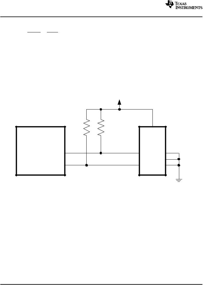
XIO3130
SLLS693E–MAY 2007–REVISED APRIL 2009 |
www.ti.com |
3.4.1Serial Bus Interface Implementation
To enable the serial bus interface, a pullup resistor must be implemented on the SDA signal. At the rising edge of PERST or GRST, whichever occurs last, the SDA terminal is checked for a pullup resistor. If one is detected, bit 3 (SBDETECT) in the serial bus control and status register (see Table 4-32) is set. Software may disable the serial bus interface at any time by writing a zero to the SBDETECT bit. If no external EEPROM is required, the serial bus interface is permanently disabled by attaching a pulldown resistor to the SDA signal.
The XIO3130 implements a two-terminal serial interface with one clock signal (SCL) and one data signal (SDA). The SCL signal is a unidirectional output from the XIO3130 and the SDA signal is bidirectional. Both are open-drain signals and require pullup resistors. The XIO3130 is a bus master device and drives SCL at approximately 60 kHz during data transfers and places SCL in a high-impedance state during bus idle states. The serial EEPROM is a bus slave device and must acknowledge a slave address equal to 1010_000X binary. Figure 3-4 illustrates a sample application implementing the two-wire serial bus.
VDD3 3
XIO3130 |
SERIAL |
|
|
EEPROM |
|
SCL |
SCL |
A2 |
|
|
A1 |
SDA |
SDA |
A0 |
Figure 3-4. Serial EEPROM Applications
3.4.2Serial Bus Interface Protocol
All data transfers are initiated by the serial bus master. The beginning of a data transfer is indicated by a start condition, which is signaled when the SDA line transitions to a low state while SCL is in the high state, as illustrated in Figure 3-5. The end of a requested data transfer is indicated by a stop condition, which is signaled by a low-to-high transition of SDA while SCL is in the high state, as shown in Figure 3-5. Data on SDA must remain stable during the high state of the SCL signal because changes on the SDA signal during the high state of SCL are interpreted as control signals (i.e., a start or a stop condition).
26 |
Description |
Submit Documentation Feedback |
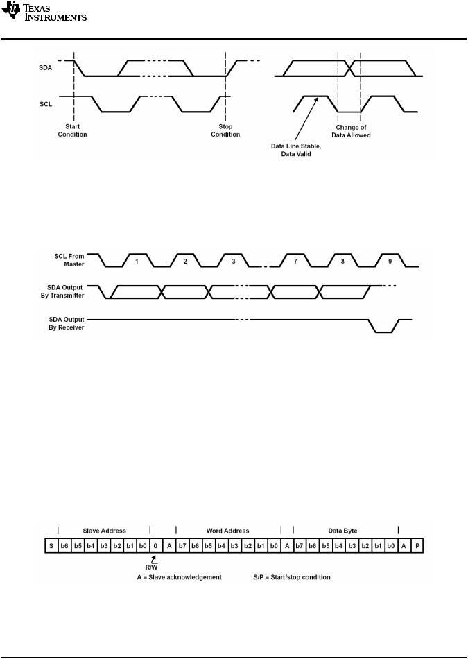
XIO3130
www.ti.com |
SLLS693E–MAY 2007–REVISED APRIL 2009 |
Figure 3-5. Serial-Bus Start/Stop Conditions and Bit Transfers
Data is transferred serially in 8-bit bytes. During a data transfer operation, an unlimited number of bytes are transmitted. However, each byte must be followed by an acknowledge bit to continue the data transfer operation. An acknowledge (ACK) is indicated by the data byte receiver pulling the SDA signal low, so that it remains low during the high state of the SCL signal. Figure 3-6 illustrates the acknowledge protocol.
Figure 3-6. Serial-Bus Protocol Acknowledge
The XIO3130 performs three basic serial bus operations: single-byte reads, single-byte writes, and multiple-byte reads. The single-byte operations occur under software control. The multiple-byte read operations are performed by the serial EEPROM initialization circuitry immediately after a PCI Express Reset. For details on how the XIO3130 automatically loads the subsystem identification and other register defaults from the serial-bus EEPROM, see Section 3.4.3, Serial Bus EEPROM Application.
Figure 3-7 illustrates a single-byte write. The XIO3130 issues a start condition and sends the 7-bit slave device address and the R/W command bit equal to zero. A zero in the R/W command bit indicates that the data transfer is a write. The slave device acknowledges that it recognizes the slave address. If the XIO3130 receives no acknowledgment, the SB_ERR status bit is set in the serial-bus control and status register (PCI offset B3h; see Table 4-32). Next, the XIO3130 sends the EEPROM word address, and another slave acknowledgment is expected. Then the XIO3130 delivers the data byte (MSB first) and expects a final acknowledgment before issuing the stop condition.
Figure 3-7. Serial-Bus Protocol – Byte Write
Figure 3-8 illustrates a single-byte read. The XIO3130 issues a start condition and sends the 7-bit slave device address and the R/W command bit equal to zero (write). The slave device acknowledges that it recognizes the slave address. Next, the XIO3130 sends the EEPROM word address, and another slave
Submit Documentation Feedback |
Description |
27 |

XIO3130
SLLS693E–MAY 2007–REVISED APRIL 2009 |
www.ti.com |
acknowledgment is expected. Then, the XIO3130 issues a restart condition followed by the 7-bit slave address and the R/W command bit equal to one (read). Once again, the slave device responds with acknowledge. Next, the slave device sends the 8-bit data byte, MS bit first. Since this is a one-byte read, the XIO3130 responds with no acknowledge (logic high), indicating the last data byte. Finally, the XIO3130 issues a stop condition.
Slave Address |
|
|
|
Word Address |
|
|
S b6 b5 |
b4 b3 b2 b1 b0 0 |
A |
b7 |
b6 |
b5 b4 b3 b2 b1 b0 |
A |
Start |
R/W |
|
|
|
|
|
|
Slave Address |
|
|
|
Data Byte |
|
S |
b6 b5 b4 b3 b2 |
b1 |
b0 1 |
A |
b7 b6 b5 b4 b3 b2 |
b1 b0 M P |
Restart |
|
R/W |
|
|
|
|
A = Slave Acknowledgement M = Master Acknowledgement S/P = Start/Stop Condition
Figure 3-8. Serial-Bus Protocol – Byte Read
Figure 3-9 illustrates the serial interface protocol during a multiple-byte serial EEPROM download. The serial bus protocol starts exactly the same way as a one-byte read. The only difference is that multiple data bytes are transferred. The number of transferred data bytes is controlled by the XIO3130 master. After each data byte, if more data bytes are requested, the XIO3130 master issues acknowledge (logic low). The transfer ends after an XIO3130 master no acknowledge (logic high), followed by a stop condition.
Figure 3-9. Serial-Bus Protocol – Multiple-Byte Read
The PROT_SEL bit (bit 7) in the Serial Bus Control and Status register changes the serial bus protocol. Each of the three previous serial-bus protocol figures illustrates the PROT_SEL bit default (logic low). When this control bit is asserted, the word address and corresponding acknowledge are removed from the serial bus protocol. This feature allows the system designer a second serial bus protocol option when selecting external EEPROM devices.
3.4.3Serial Bus EEPROM Application
The registers and corresponding bits that are loaded through the EEPROM are provided in Table 3-3. Note the following:
∙EEPROM bytes 00h through 1Dh affect the general control options for the XIO3130.
∙EEPROM bytes 1Eh through 27h affect the operation of the upstream port (port 0).
∙Bytes 00h through 27h are loaded into the configuration registers for the upstream virtual bridge or port 0 (see Figure 4-1).
∙EEPROM bytes 28h through 35h correspond to and are loaded into the configuration space for the first downstream virtual bridge or port 1 (see Figure 4-1).
28 |
Description |
Submit Documentation Feedback |

XIO3130
www.ti.com |
SLLS693E–MAY 2007–REVISED APRIL 2009 |
∙EEPROM bytes 36h through 43h correspond to and are loaded into the configuration space for the second downstream virtual bridge or port 2 (see Figure 4-1).
∙EEPROM bytes 44h through 51h correspond to and are loaded into the configuration space for the third downstream virtual bridge or port 3 (see Figure 4-1).
Table 3-3. EEPROM Register Loading Map
EEPROM Byte Address |
Suggested Programmed |
CONFIG Register Address |
Register Description |
|
(hex) |
Value (hex) |
(hex) |
||
|
||||
0 |
4C |
NA |
Global Switch/Upstream Port Function Indicator(1) |
|
1 |
0 |
NA |
TI Proprietary register(1) |
|
2 |
24 |
0B4 |
Upstream Port Link PM Latency register |
|
3 |
0 |
0B5 |
Upstream Port Link PM Latency register |
|
4 |
0 |
0B8 |
Global Chip Control register |
|
5 |
0 |
0B9 |
Global Chip Control register |
|
6 |
0 |
0BA |
Global Chip Control register |
|
7 |
0 |
0BB |
Global Chip Control register |
|
8 |
0 |
0BC |
GPIOA register |
|
9 |
0 |
0BD |
GPIOA register |
|
0A |
0 |
0BE |
GPIOB register |
|
0B |
0 |
0BF |
GPIOB register |
|
0C |
0 |
0C0 |
GPIOC register |
|
0D |
0 |
0C1 |
GPIOC register |
|
0E |
0 |
0C2 |
GPIOD register |
|
0F |
0 |
0C3 |
GPIOD register |
|
10 |
0 |
0C4 |
GPIO Data register |
|
11 |
0 |
0C5 |
GPIO Data register |
|
12 |
0 |
0C6 |
GPIO Data register |
|
13 |
0 |
0C7 |
GPIO Data register |
|
14 |
01 |
0C8 |
TI Proprietary register(1) |
|
15 |
0 |
0CC |
TI Proprietary register(1) |
|
16 |
0 |
0CD |
TI Proprietary register(1) |
|
17 |
0 |
0D0 |
TI Proprietary register(1) |
|
18 |
0 |
0D1 |
TI Proprietary register(1) |
|
19 |
14 |
0D2 |
TI Proprietary register(1) |
|
1A |
32 |
0D3 |
TI Proprietary register(1) |
|
1B |
2 |
0DC |
TI Proprietary register(1) |
|
1C |
0 |
0DE |
TI Proprietary register(1) |
|
1D |
0 |
0DF |
TI Proprietary register(1) |
|
1E |
0 |
NA |
Global Switch/Upstream Port 0 Function Indicator |
|
1F |
0 |
NA |
Not used |
|
20 |
XX |
0E0 |
Subsystem Access Vendor ID register |
|
21 |
XX |
0E1 |
Subsystem Access Vendor ID register |
|
22 |
XX |
0E2 |
Subsystem Access Subsys ID register |
|
23 |
XX |
0E3 |
Subsystem Access Subsys ID register |
|
24 |
0 |
0E4 |
General Control register |
|
25 |
24 |
0E8 |
Downstream Port Link PM Latency register |
|
26 |
3F |
0E9 |
Downstream Port Link PM Latency register |
|
27 |
4 |
0EA |
Global Switch Control register |
|
28 |
1 |
NA |
Downstream Port 1 Function Indicator |
(1)Required program value
Submit Documentation Feedback |
Description |
29 |

XIO3130
SLLS693E–MAY 2007–REVISED APRIL 2009 www.ti.com
Table 3-3. EEPROM Register Loading Map (continued)
EEPROM Byte Address |
Suggested Programmed |
CONFIG Register Address |
Register Description |
|
(hex) |
Value (hex) |
(hex) |
||
|
||||
29 |
0 |
NA |
Not used |
|
2A |
01 |
0C8 |
TI Proprietary register(1) |
|
2B |
0 |
0CC |
TI Proprietary register(1) |
|
2C |
0 |
0CD |
TI Proprietary register(1) |
|
2D |
0 |
0D0 |
TI Proprietary register(1) |
|
2E |
0 |
0D1 |
TI Proprietary register(1) |
|
2F |
14 |
0D2 |
TI Proprietary register(1) |
|
30 |
32 |
0D3 |
TI Proprietary register(1) |
|
31 |
10 |
0D4 |
General Control register |
|
32 |
60 |
0D5 |
General Control register |
|
33 |
1A |
0EC |
L0s Timeout register |
|
34 |
0 |
0EE |
General Slot Info register |
|
35 |
0 |
0EF |
General Slot Info register |
|
36 |
2 |
NA |
Downstream Port 2 Function Indicator |
|
37 |
0 |
NA |
Not used |
|
38 |
01 |
0C8 |
TI Proprietary register(1) |
|
39 |
0 |
0CC |
TI Proprietary register(1) |
|
3A |
0 |
0CD |
TI Proprietary register(1) |
|
3B |
0 |
0D0 |
TI Proprietary register(1) |
|
3C |
0 |
0D1 |
TI Proprietary register(1) |
|
3D |
14 |
0D2 |
TI Proprietary register(1) |
|
3E |
32 |
0D3 |
TI Proprietary register(1) |
|
3F |
10 |
0D4 |
General Control register |
|
40 |
60 |
0D5 |
General Control register |
|
41 |
1A |
0EC |
L0s Timeout register |
|
42 |
0 |
0EE |
General Slot Info register |
|
43 |
0 |
0EF |
General Slot Info register |
|
44 |
2 |
NA |
Downstream Port 3 Function Indicator |
|
45 |
0 |
NA |
Not used |
|
46 |
01 |
0C8 |
TI Proprietary register(1) |
|
47 |
0 |
0CC |
TI Proprietary register(1) |
|
48 |
0 |
0CD |
TI Proprietary register(1) |
|
49 |
0 |
0D0 |
TI Proprietary register(1) |
|
4A |
0 |
0D1 |
TI Proprietary register(1) |
|
4B |
14 |
0D2 |
TI Proprietary register(1) |
|
4C |
32 |
0D3 |
TI Proprietary register(1) |
|
4D |
10 |
0D4 |
General Control register |
|
4E |
60 |
0D5 |
General Control register |
|
4F |
1A |
0EC |
L0s Timeout register |
|
50 |
0 |
0EE |
General Slot Info register |
|
51 |
0 |
0EF |
General Slot Info register |
30 |
Description |
Submit Documentation Feedback |
Loading...