


Burr Brown Products from Texas Instruments
INA20x
INA20x
INA20x
INA206
INA207
INA208
SBOS360C – JUNE 2006 – REVISED JUNE 2007
Unidirectional Measurement Current-Shunt Monitor with Dual Comparators
FEATURES
∙COMPLETE CURRENT SENSE SOLUTION
∙DUAL COMPARATORS:
–Comparator 1 with Latch
–Comparator 2 with Optional Delay
∙COMMON-MODE RANGE: –16V to +80V
∙HIGH ACCURACY: 3.5% (max) OVER TEMP
∙BANDWIDTH: 500kHz
∙QUIESCENT CURRENT: 1.8mA
∙PACKAGES: SO-14, TSSOP-14, MSOP-10
APPLICATIONS |
|
|
||
∙ |
NOTEBOOK COMPUTERS |
|
|
|
∙ |
CELL PHONES |
|
|
|
∙ |
TELECOM EQUIPMENT |
|
|
|
∙ |
AUTOMOTIVE |
|
|
|
∙ |
POWER MANAGEMENT |
|
|
|
∙ |
BATTERY CHARGERS |
|
|
|
∙ |
WELDING EQUIPMENT |
|
|
|
|
|
INA206−INA208 |
|
|
|
VS |
1 |
14 |
VIN+ |
|
OUT |
2 |
13 |
VIN− |
CMP1 IN−/0.6V REF |
1.2V REF |
|
1.2V REF OUT |
|
3 |
12 |
|||
|
CMP1 IN+ |
4 |
11 |
CMP1 OUT |
|
CMP2 IN− |
5 |
10 |
CMP2 OUT |
CMP2 IN+/0.6V REF |
6 |
9 |
CMP2 DELAY |
|
|
GND |
7 |
8 |
CMP1 RESET |
|
|
SO -14, TSSOP-14 |
|
|
DEVICE |
GAIN |
INA206 |
20V/V |
INA207 |
50V/V |
INA208 |
100V/V |
DESCRIPTION
The INA206, INA207, and INA208 are a family of unidirectional, current-shunt monitors with voltage output, dual comparators, and voltage reference. The INA206, INA207, and INA208 can sense drops across shunts at common-mode voltages from –16V to +80V. The INA206, INA207, and INA208 are available with three output voltage scales: 20V/V, 50V/V, and 100V/V, with up to 500kHz bandwidth.
The INA206, INA207, and INA208 also incorporate two open-drain comparators with internal 0.6V references. On 14-pin versions, the comparator references can be overridden by external inputs. Comparator 1 includes a latching capability, and Comparator 2 has a user-programmable delay on 14-pin versions. 14-pin versions also provide a 1.2V reference output.
The INA206, INA207, and INA208 operate from a single +2.7V to +18V supply. They are specified over the extended operating temperature range of –40°C to +125°C.
|
|
INA206−INA208 |
|
VS |
1 |
10 |
VIN+ |
OUT |
2 |
9 |
VIN− |
CMP1 IN+ |
3 |
8 |
CMP1 OUT |
CMP2 IN− |
4 |
7 |
CMP2 OUT |
GND |
5 |
6 |
CMP1 RESET |
|
|
0.6V REF |
|
|
|
MSOP-10 |
|
RELATED PRODUCTS
FEATURES |
PRODUCT |
Variant of INA206–INA208 Comparator 2 |
INA203–INA205 |
polarity |
|
Current-shunt monitor with single |
INA200–INA202 |
comparator and VREF |
|
Current-shunt monitor only |
INA193–INA198 |
Current-shunt monitor with split stages for |
INA270–INA271 |
filter options |
|
Please be aware that an important notice concerning availability, standard warranty, and use in critical applications of Texas Instruments semiconductor products and disclaimers thereto appears at the end of this data sheet.
All trademarks are the property of their respective owners.
PRODUCTION DATA information is current as of publication date. |
Copyright © 2006–2007, Texas Instruments Incorporated |
Products conform to specifications per the terms of the Texas |
|
Instruments standard warranty. Production processing does not |
|
necessarily include testing of all parameters. |
|
INA206
INA207
INA208
www.ti.com
SBOS360C – JUNE 2006 – REVISED JUNE 2007
This integrated circuit can be damaged by ESD. Texas Instruments recommends that all integrated circuits be handled with appropriate precautions. Failure to observe proper handling and installation procedures can cause damage.
ESD damage can range from subtle performance degradation to complete device failure. Precision integrated circuits may be more susceptible to damage because very small parametric changes could cause the device not to meet its published specifications.
ORDERING INFORMATION(1)
|
|
|
|
|
|
EXTERNAL |
INTERNAL |
|
|
|
|
|
|
|
COMP1 AND |
COMP1 AND |
|
|
|
|
PACKAGE |
PACKAGE |
1.2V |
COMP2 |
COMP2 |
COMP2 |
PRODUCT |
GAIN |
PACKAGE-LEAD |
DESIGNATOR |
MARKING |
REF OUT |
REF INPUTS |
0.6V REF |
DELAY PIN |
|
|
SO-14 |
D |
INA206A |
X |
X |
X |
X |
INA206 |
20V/V |
MSOP-10 |
DGS |
BQQ |
|
|
X |
|
|
|
TSSOP-14 |
PW |
INA206A |
X |
X |
X |
X |
|
|
SO-14 |
D |
INA207A |
X |
X |
X |
X |
INA207 |
50V/V |
MSOP-10 |
DGS |
BQR |
|
|
X |
|
|
|
TSSOP-14 |
PW |
INA207A |
X |
X |
X |
X |
|
|
SO-14 |
D |
INA208A |
X |
X |
X |
X |
INA208 |
100V/V |
MSOP-10 |
DGS |
BQS |
|
|
X |
|
|
|
TSSOP-14 |
PW |
INA208A |
X |
X |
X |
X |
(1)For the most current package and ordering information see the Package Option Addendum at the end of this document, or see the TI web site at www.ti.com. Packages listed above but not found in the Package Option Addendum are preview packages.
ABSOLUTE MAXIMUM RATINGS(1)
|
|
INA206, INA207, INA208 |
UNIT |
|
Supply Voltage, V+ |
|
18 |
V |
|
Current-Shunt Monitor Analog Inputs, |
Differential (VIN+) – (VIN–) |
–18 to +18 |
V |
|
VIN+ and VIN– |
Common-Mode |
–16 to +80 |
V |
|
Comparator Analog Input and Reset Pins |
GND – 0.3 to (V+) + 0.3 |
V |
||
Analog Output, Out Pin |
|
GND – 0.3 to (V+) + 0.3 |
V |
|
Comparator Output, Out Pin |
|
GND – 0.3 to 18 |
V |
|
VREF and CMP2 Delay Pin |
|
GND – 0.3 to 10 |
V |
|
Input Current Into Any Pin |
|
5 |
mA |
|
Operating Temperature |
|
–55 to +150 |
°C |
|
Storage Temperature |
|
–65 to +150 |
°C |
|
Junction Temperature |
|
+150 |
°C |
|
ESD Ratings |
Human Body Model (HBM) |
4000 |
V |
|
Charged Device Model (CDM) |
500 |
V |
||
|
||||
(1)Stresses above these ratings may cause permanent damage. Exposure to absolute maximum conditions for extended periods may degrade device reliability. These are stress ratings only, and functional operation of the device at these or any other conditions beyond those specified is not supported.
2 |
Submit Documentation Feedback |

INA206 INA207
INA208
www.ti.com
SBOS360C – JUNE 2006 – REVISED JUNE 2007
ELECTRICAL CHARACTERISTICS
Boldface limits apply over the specified temperature range, TA = –40°C to +125°C.
At TA = +25°C, VS = +12V, VIN+ = 12V, VSENSE = 100mV, RL = 10kΩ to GND, RPULL-UP = 5.1kΩ each connected from CMP1 OUT and CMP2 OUT to VS, and CMP1 IN+ = 1V and CMP2 IN– = GND, unless otherwise noted.
CURRENT-SHUNT MONITOR |
|
|
|
INA206, INA207, INA208 |
|
|
|
|
|
|
|
|
|
PARAMETERS |
|
TEST CONDITIONS |
MIN |
TYP |
MAX |
UNIT |
INPUT |
|
|
|
|
|
|
Full-Scale Sense Input Voltage |
VSENSE |
VSENSE = VIN+ – VIN– |
|
0.15 |
(VS – |
V |
|
|
|
|
|
0.25)/Gain |
|
Common-Mode Input Range |
VCM |
|
–16 |
|
80 |
V |
Common-Mode Rejection Ratio |
CMRR |
VIN+ = –16V to +80V |
80 |
100 |
|
dB |
over Temperature |
|
VIN+ = +12V to +80V |
100 |
123 |
|
dB |
Offset Voltage RTI(1) |
VOS |
|
|
±0.5 |
±2.5 |
mV |
+25°C to +125°C |
|
|
|
|
±3 |
mV |
–40°C to +25°C |
|
|
|
|
±3.5 |
mV |
vs Temperature |
dVOS/dT |
–40°C to +125°C |
|
5 |
|
μV/°C |
vs Power-Supply |
PSR |
VOUT = 2V, VIN+ = 18V, 2.7V |
|
2.5 |
100 |
μV/V |
Input Bias Current, VIN– Pin |
IB |
|
|
±9 |
±16 |
μA |
OUTPUT (VSENSE ³ 20mV) |
|
|
|
|
|
|
Gain: INA206 |
G |
|
|
20 |
|
V/V |
Gain: INA207 |
|
|
|
50 |
|
V/V |
Gain: INA208 |
|
|
|
100 |
|
V/V |
Gain Error |
|
VSENSE = 20mV to 100mV |
|
±0.2 |
±1 |
% |
over Temperature |
|
VSENSE = 20mV to 100mV |
|
|
±2 |
% |
Total Output Error(2) |
|
VSENSE = 120mV, VS = +16V |
|
±0.75 |
±2.2 |
% |
over Temperature |
|
VSENSE = 120mV, VS = +16V |
|
|
±3.5 |
% |
Nonlinearity Error(3) |
|
VSENSE = 20mV to 100mV |
|
±0.002 |
|
% |
Output Impedance |
RO |
|
|
1.5 |
|
W |
Maximum Capacitive Load |
|
No Sustained Oscillation |
|
10 |
|
nF |
OUTPUT (VSENSE < 20mV)(4) |
|
|
|
|
|
|
INA206, INA207, INA208 |
|
–16V £ VCM < 0V |
|
300 |
|
mV |
INA206 |
|
0V £ VCM £ VS, VS = 5V |
|
|
0.4 |
V |
INA207 |
|
0V £ VCM £ VS, VS = 5V |
|
|
1 |
V |
INA208 |
|
0V £ VCM £ VS, VS = 5V |
|
|
2 |
V |
INA206, INA207, INA208 |
|
VS < VCM £ 80V |
|
300 |
|
mV |
VOLTAGE OUTPUT(5) |
|
|
|
|
|
|
Output Swing to the Positive Rail |
|
VIN– = 11V, VIN+ = 12V |
|
(V+) – 0.15 |
(V+) – 0.25 |
V |
Output Swing to GND(6) |
|
VIN– = 0V, VIN+ = –0.5V |
|
(VGND) + 0.004 |
(VGND) + 0.05 |
V |
FREQUENCY RESPONSE |
|
|
|
|
|
|
Bandwidth: INA206 |
BW |
CLOAD = 5pF |
|
500 |
|
kHz |
Bandwidth: INA207 |
|
CLOAD = 5pF |
|
300 |
|
kHz |
Bandwidth: INA208 |
|
CLOAD = 5pF |
|
200 |
|
kHz |
Phase Margin |
|
CLOAD < 10pF |
|
40 |
|
Degrees |
Slew Rate |
|
|
|
1 |
|
V/μs |
Settling Time (1%) |
|
VSENSE = 10mVPP to 100mVPP, |
|
2 |
|
μs |
|
|
CLOAD = 5pF |
|
|
|
|
NOISE, RTI |
|
|
|
|
|
|
Output Voltage Noise Density |
|
|
|
40 |
|
nV/ÖHz |
(1)Offset is extrapolated from measurements of the output at 20mV and 100mV VSENSE.
(2)Total output error includes effects of gain error and VOS.
(3)Linearity is best fit to a straight line.
(4)For details on this region of operation, see the Accuracy Variations as a Result of VSENSE and Common-Mode Voltage section in the Applications Information.
(5)See Typical Characteristics curve Output Swing vs Output Current.
(6)Specified by design.
Submit Documentation Feedback |
3 |

INA206
INA207
INA208
www.ti.com
SBOS360C – JUNE 2006 – REVISED JUNE 2007
ELECTRICAL CHARACTERISTICS
Boldface limits apply over the specified temperature range, TA = –40°C to +125°C.
At TA = +25°C, VS = +12V, VIN+ = 12V, VSENSE = 100mV, RL = 10kΩ to GND, RPULL-UP = 5.1kΩ each connected from CMP1 OUT and CMP2 OUT to VS, unless otherwise noted.
|
|
|
INA206, INA207, INA208 |
|
||
COMPARATOR PARAMETERS |
|
TEST CONDITIONS |
MIN |
TYP |
MAX |
UNIT |
OFFSET VOLTAGE |
|
|
|
|
|
|
Offset Voltage |
|
Comparator Common-Mode Voltage = Threshold Voltage |
|
2 |
|
mV |
Offset Voltage Drift, Comparator 1 |
|
|
|
±2 |
|
μV/°C |
Offset Voltage Drift, Comparator 2 |
|
|
|
+5.4 |
|
μV/°C |
Threshold |
|
TA = +25°C |
590 |
600 |
610 |
mV |
over Temperature |
|
|
586 |
|
614 |
mV |
Hysteresis(1), CMP1 |
|
TA = –40°C to +85°C |
|
–8 |
|
mV |
Hysteresis(1), CMP2 |
|
TA = –40°C to +85°C |
|
8 |
|
mV |
INPUT BIAS CURRENT(2) |
|
|
|
|
|
|
CMP1 IN+, CMP2 IN– |
|
|
|
0.005 |
10 |
nA |
vs Temperature |
|
|
|
|
15 |
nA |
INPUT IMPEDANCE |
|
|
|
|
|
|
Pins 3 and 6 (14-pin packages only) |
|
|
|
10 |
|
kW |
INPUT RANGE |
|
|
|
|
|
|
CMP1 IN+ and CMP2 IN– |
|
|
|
0V to VS – 1.5V |
|
V |
Pins 3 and 6 (14-pin packages only)(3) |
|
|
|
0V to VS – 1.5V |
|
V |
OUTPUT |
|
|
|
|
|
|
Large-Signal Differential Voltage Gain |
|
CMP VOUT 1V to 4V, RL ³ 15kW connected to 5V |
|
200 |
|
V/mV |
High-Level Output Current |
|
VID = 0.4V, VOH = VS |
|
0.0001 |
1 |
μA |
Low-Level Output Voltage |
|
VID = –0.6V, IOL = 2.35mA |
|
220 |
300 |
mV |
RESPONSE TIME(4) |
|
|
|
|
|
|
Comparator 1 |
|
RL to 5V, CL = 15pF, 100mV Input Step with 5mV Overdrive |
|
1.3 |
|
μs |
Comparator 2 |
|
RL to 5V, CL = 15pF, 100mV Input Step with 5mV Overdrive, |
|
1.3 |
|
μs |
|
|
CDELAY Pin Open |
|
|
|
|
RESET |
|
|
|
|
|
|
RESET Threshold(5) |
|
|
|
1.1 |
|
V |
Logic Input Impedance |
|
|
|
2 |
|
MW |
Minimum RESET Pulse Width |
|
|
|
1.5 |
|
μs |
RESET Propagation Delay |
|
|
|
3 |
|
μs |
Comparator 2 Delay Equation(6) |
|
|
|
CDELAY = tD/5 |
|
μF |
Comparator 2 Delay |
tD |
CDELAY = 0.1μF |
|
0.5 |
|
s |
(1)Hysteresis refers to the threshold (the threshold specification applies to a rising edge of a noninverting input) of a falling edge on the noninverting input of the comparator. Refer to Figure 1.
(2)Specified by design.
(3)See the Comparator Maximum Input Voltage Range section in the Applications Information.
(4)The comparator response time specified is the interval between the input step function and the instant when the output crosses 1.4 V.
(5)RESET input has an internal 2MΩ (typical) pull-down. Leaving RESET open results in a LOW state, with transparent comparator operation.
(6)The Comparator 2 delay applies to both rising and falling edges of the comparator output.
|
|
|
VTHRESHOLD |
|
VTHRESHOLD |
|||||||
0.592 |
|
0.6 |
0.6 |
|
0.608 |
|
||||||
|
|
|||||||||||
Input Voltage |
|
|
|
|
|
|
|
|
|
|
Input Voltage |
|
|
|
|
|
|
|
|
|
|
|
|
||
|
|
|
|
|
|
|
||||||
|
|
|
|
|
|
|
|
|
|
|
|
|
|
|
|
|
|
|
|
|
|
|
|
||
|
|
|
|
|
|
|
|
|
|
|
|
|
Hysteresis = VTHRESHOLD – 8mV |
|
Hysteresis = VTHRESHOLD – 8mV |
||||||||||
|
a) CMP1 |
|
|
|
|
|
b) CMP2 |
|||||
Figure 1. Comparator Hysteresis
4 |
Submit Documentation Feedback |

INA206 INA207
INA208
www.ti.com
SBOS360C – JUNE 2006 – REVISED JUNE 2007
ELECTRICAL CHARACTERISTICS
Boldface limits apply over the specified temperature range, TA = –40°C to +125°C.
At TA = +25°C, VS = +12V, VIN+ = 12V, VSENSE = 100mV, RL = 10kΩ to GND, RPULL-UP = 5.1kΩ each connected from CMP1 OUT and CMP2 OUT to VS, unless otherwise noted.
|
|
|
INA206, INA207, INA208 |
|
||
REFERENCE PARAMETERS |
|
TEST CONDITIONS |
MIN |
TYP |
MAX |
UNIT |
REFERENCE VOLTAGE |
|
|
|
|
|
|
1.2VREFOUT Output Voltage |
|
|
1.188 |
1.2 |
1.212 |
V |
Reference Drift |
dVOUT/dT |
TA = –40°C to +85°C |
|
40 |
100 |
ppm/°C |
0.6VREF Output Voltage |
|
|
|
0.6 |
|
V |
(Pins 3 and 6 of 14-pin packages only) |
|
|
|
|
|
|
Reference Drift |
dVOUT/dT |
LOAD REGULATION |
dVOUT/dILOAD |
Sourcing |
|
Sinking |
|
LOAD CURRENT |
ILOAD |
LINE REGULATION |
dVOUT/dVS |
CAPACITIVE LOAD |
|
Reference Output Max. Capacitive Load |
|
TA = –40°C to +85°C |
40 |
100 |
ppm/°C |
0mA < ISOURCE < 0.5mA |
0.4 |
2 |
mV/mA |
0mA < ISINK < 0.5mA |
0.4 |
|
mV/mA |
|
1 |
|
mA |
2.7V < VS < 18V |
30 |
|
μV/V |
No Sustained Oscillations |
10 |
|
nF |
OUTPUT IMPEDANCE |
|
|
Pins 3 and 6 of 14-Pin Packages Only |
10 |
kΩ |
ELECTRICAL CHARACTERISTICS
Boldface limits apply over the specified temperature range, TA = –40°C to +125°C.
At TA = +25°C, VS = +12V, VIN+ = 12V, VSENSE = 100mV, RL = 10kΩ to GND, RPULL-UP = 5.1kΩ each connected from CMP1 OUT and CMP2 OUT to VS, and CMP1 IN+ = 1V and CMP2 IN– = GND, unless otherwise noted.
|
|
|
INA206, INA207, INA208 |
|
||
GENERAL PARAMETERS |
|
TEST CONDITIONS |
MIN |
TYP |
MAX |
UNIT |
POWER SUPPLY |
|
|
|
|
|
|
Operating Power Supply |
VS |
|
+2.7 |
|
+18 |
V |
Quiescent Current |
IQ |
VOUT = 2V |
|
1.8 |
2.2 |
mA |
over Temperature |
|
VSENSE = 0mV |
|
|
2.8 |
mA |
Comparator Power-On Reset Threshold(1) |
|
|
|
1.5 |
|
V |
TEMPERATURE |
|
|
|
|
|
|
Specified Temperature Range |
|
|
–40 |
|
+125 |
°C |
Operating Temperature Range |
|
|
–55 |
|
+150 |
°C |
Storage Temperature Range |
|
|
–65 |
|
+150 |
°C |
Thermal Resistance |
θJA |
|
|
|
|
|
MSOP-10 Surface-Mount |
|
|
|
200 |
|
°C/W |
SO-14, TSSOP-14 Surface-Mount |
|
|
|
150 |
|
°C/W |
(1)The INA206, INA207, and INA208 are designed to power-up with the comparator in a defined reset state as long as CMP1 RESET is open or grounded. The comparator will be in reset as long as the power supply is below the voltage shown here. The comparator will assume a state based on the comparator input above this supply voltage. If CMP1 RESET is high at power-up, the comparator output comes up high and requires a reset to assume a low state, if appropriate.
Submit Documentation Feedback |
5 |

INA206
INA207
INA208
www.ti.com
SBOS360C – JUNE 2006 – REVISED JUNE 2007
TYPICAL CHARACTERISTICS
All specifications at TA = +25°C, VS = +12V, VIN+ = 12V, and VSENSE = 100mV, unless otherwise noted.
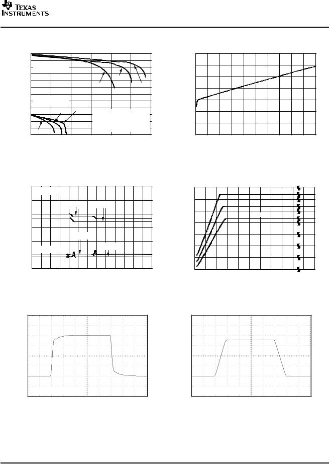
GAIN vs FREQUENCY
|
45 |
|
|
|
|
40 |
G = 100 |
|
CLOAD = 1000pF |
|
|
|
|
|
|
35 |
G = 50 |
|
|
|
|
|
|
|
(dB) |
30 |
|
|
|
|
G=20 |
|
|
|
25 |
|
|
|
|
Gain |
|
|
|
|
20 |
|
|
|
|
|
|
|
|
|
|
15 |
|
|
|
|
10 |
|
|
|
|
5 |
|
|
|
|
10k |
|
100k |
1M |
Frequency (Hz)
Figure 2.
GAIN PLOT
|
20 |
|
|
|
|
|
|
|
|
|
|
18 |
|
|
|
|
|
|
|
|
|
|
100V/V |
|
|
|
|
|
|
|
|
|
|
16 |
|
|
|
|
|
|
|
|
|
|
14 |
|
|
50V/V |
|
|
|
|
|
|
(V) |
12 |
|
|
|
|
|
|
|
||
|
|
|
|
|
|
|
|
|
||
|
|
|
|
|
|
|
|
|
|
|
OUT |
10 |
|
|
|
|
|
|
|
|
|
|
|
|
|
|
|
|
|
|
|
|
V |
8 |
|
|
|
|
|
|
|
|
|
|
|
|
|
|
20V/V |
|
|
|
||
|
6 |
|
|
|
|
|
|
|
||
|
|
|
|
|
|
|
|
|
|
|
|
4 |
|
|
|
|
|
|
|
|
|
|
2 |
|
|
|
|
|
|
|
|
|
|
0 |
|
|
|
|
|
|
|
|
|
|
20 |
100 |
200 |
300 |
400 |
500 |
600 |
700 |
800 |
900 |
VSENSE (mV)
Figure 4.
OUTPUT ERROR vs VSENSE
value) |
4.0 |
|
3.5 |
||
|
||
ErrorOutput outputidealtheof |
3.0 |
|
2.5 |
||
|
||
|
2.0 |
|
error(% |
1.5 |
|
0.5 |
||
|
1.0 |
|
|
0 |
0 |
50 |
100 |
150 |
200 |
250 |
300 |
350 |
400 |
450 |
500 |
VSENSE (mV)
Figure 6.
GAIN vs FREQUENCY
|
45 |
|
|
|
40 |
G = 100 |
|
|
|
|
|
|
35 |
G=50 |
|
|
|
|
|
(dB) |
30 |
|
|
|
G=20 |
|
|
25 |
|
|
|
Gain |
|
|
|
20 |
|
|
|
|
|
|
|
|
15 |
|
|
|
10 |
|
|
|
5 |
|
|
|
10k |
100k |
1M |
Frequency (Hz)
Figure 3.
COMMON-MODE AND POWER-SUPPLY REJECTION vs FREQUENCY
|
|
140 |
|
|
|
|
|
Rejection(dB) |
130 |
|
|
|
|
Mode and |
120 |
|
CMRR |
|
|
|
|
|
|
|
|||
110 |
|
|
|
|
||
100 |
|
|
|
|
||
90 |
|
|
|
|
||
Common-- |
Power--Supply |
|
PSR |
|
|
|
|
|
|
|
|||
80 |
|
|
|
|
||
70 |
|
|
|
|
||
60 |
|
|
|
|
||
|
|
|
|
|
||
|
|
50 |
|
|
|
|
|
|
40 |
|
|
|
|
|
|
10 |
100 |
1k |
10k |
100k |
|
|
|
|
Frequency (Hz) |
|
|
Figure 5.
OUTPUT ERROR vs COMMON-MODE VOLTAGE
|
0.1 |
|
|
|
|
|
|
|
|
|
|
|
|
0.09 |
|
|
|
|
|
|
|
|
|
|
|
|
0.08 |
|
|
|
|
|
|
|
|
|
|
|
) |
0.07 |
|
|
|
|
|
|
|
|
|
|
|
(% |
|
|
|
|
|
|
|
|
|
|
|
|
0.06 |
|
|
|
|
|
|
|
|
|
|
|
|
Error |
|
|
|
|
|
|
|
|
|
|
|
|
0.05 |
|
|
|
|
|
|
|
|
|
|
|
|
Output |
0.04 |
|
|
|
|
|
|
|
|
|
|
|
0.03 |
|
|
|
|
|
|
|
|
|
|
|
|
|
|
|
|
|
|
|
|
|
|
|
|
|
|
0.02 |
|
|
|
|
|
|
|
|
|
|
|
|
0.01 |
|
|
|
|
|
|
|
|
|
|
|
|
0 |
|
|
|
|
|
|
|
|
|
|
|
|
–16 –12 |
–8 |
–4 |
0 |
4 |
8 |
12 |
16 |
20 |
... |
76 |
80 |
|
|
Common-- Mode Voltage (V)
Figure 7.
6 |
Submit Documentation Feedback |
www.ti.com
|
|
|
POSITIVE OUTPUT VOLTAGE SWING |
|||||
|
|
|
|
vs OUTPUT CURRENT |
|
|
||
|
12 |
|
|
|
|
|
|
|
|
11 |
VS |
= 12V |
|
|
|
|
|
|
10 |
|
|
|
|
|
||
|
Sourcing Current |
|
|
|
|
|||
|
9 |
|
|
|
|
|||
(V) |
|
|
|
|
+25°C |
|
|
|
8 |
|
|
|
|
|
|
||
Voltage |
|
|
|
|
|
|
–40°C |
|
7 |
|
|
|
+125°C |
|
|||
|
|
|
|
|
||||
|
|
|
|
|
|
|
|
|
|
6 |
VS = 3V |
|
|
|
|
|
|
Output |
5 |
|
|
|
|
|
||
|
|
+25 C |
|
|
|
|
||
|
4 |
Sourcing Current |
|
|
|
|
||
|
|
|
° |
–40°C |
Output stage is designed |
|||
|
3 |
|
|
|
|
|||
|
|
|
|
|
to source current. Current |
|||
|
2 |
|
|
|
|
|||
|
|
|
|
|
sinking capabilty is |
|
||
|
|
|
|
|
|
|
||
|
1 |
+125°C |
|
|
approximately 400 A. |
|||
|
0 |
|
|
|
|
|
||
|
|
|
|
|
|
|
|
|
|
|
0 |
5 |
10 |
15 |
20 |
25 |
30 |
Output Current (mA)
Figure 8.
QUIESCENT CURRENT
vs COMMON-MODE VOLTAGE
|
2.50 |
|
|
|
|
|
|
|
|
|
|
|
|
|
VSENSE = 100mV |
|
|
|
|
|
|
|
|
|
|||
|
2.25 |
|
|
VS = 12V |
VS = 2.7V |
|
|
|
|
||||
|
|
|
|
|
|
|
|
||||||
|
2.00 |
|
|
|
|
|
|
|
|
|
|
|
|
(mA) |
1.75 |
|
|
|
|
|
|
|
|
|
|
|
|
Q |
|
|
|
|
|
|
|
|
|
|
|
|
|
I |
|
|
|
VS |
= 12V |
|
|
|
|
|
|
|
|
|
|
|
|
|
|
|
|
|
|
|
|||
|
1.50 |
|
|
|
|
|
|
|
|
|
|
|
|
|
VSENSE = 0mV |
|
|
|
|
VS = 2.7V |
|
|
|
|
|||
|
|
|
|
|
|
|
|
|
|
|
|||
|
1.25 |
|
|
|
|
|
|
|
|
|
|
|
|
|
1.00 |
|
|
|
|
|
|
|
|
|
|
|
|
|
–16 –12 |
–8 |
–4 |
0 |
4 |
8 |
12 |
16 |
20 |
24 |
28 |
32 |
36 |
|
|
|
|
|
|
VCM (V) |
|
|
|
|
|
|
|
Figure 10.
STEP RESPONSE
G = 20
Output Voltage (50mV/div)
VSENSE = 10mV to 20mV
Time (2 s/div)
Figure 12.
INA206
INA207
INA208
SBOS360C – JUNE 2006 – REVISED JUNE 2007
QUIESCENT CURRENT vs OUTPUT VOLTAGE
|
3.5 |
|
3.0 |
|
2.5 |
(mA) |
2.0 |
|
|
Q |
1.5 |
I |
1.0
0.5
0
0 |
1 |
2 |
3 |
4 |
5 |
6 |
7 |
8 |
9 |
10 |
Output Voltage (V)
Figure 9.
OUTPUT SHORT-CIRCUIT CURRENT vs SUPPLY VOLTAGE
|
34 |
|
|
|
|
|
|
|
–40°C |
|
|
|
(mA) |
|
|
|
|
|
|
|
|
|
|
|
|
30 |
|
|
|
|
|
+25°C |
|
|
|
|||
|
|
|
|
|
|
|
|
|
||||
Current |
|
|
|
|
|
|
|
|
|
|||
26 |
|
|
|
|
+125°C |
|
|
|
|
|
||
|
|
|
|
|
|
|
|
|
|
|||
|
|
|
|
|
|
|
|
|
|
|
|
|
--Circuit |
22 |
|
|
|
|
|
|
|
|
|
|
|
18 |
|
|
|
|
|
|
|
|
|
|
|
|
Short |
14 |
|
|
|
|
|
|
|
|
|
|
|
Output |
10 |
|
|
|
|
|
|
|
|
|
|
|
|
|
|
|
|
|
|
|
|
|
|
|
|
|
6 |
|
|
|
|
|
|
|
|
|
|
|
|
2.5 |
3.5 |
4.5 |
5.5 |
6.5 |
7.5 |
8.5 |
9.5 |
10.5 |
11.5 |
17 |
18 |
|
|
|
|
|
Supply Voltage (V) |
|
|
|
|
|||
Figure 11.
STEP RESPONSE
G = 20
Output Voltage (500mV/div)
VSENSE = 10mV to 100mV
Time (2 s/div)
Figure 13.
Submit Documentation Feedback |
7 |
INA206
INA207
INA208
SBOS360C – JUNE 2006 – REVISED JUNE 2007
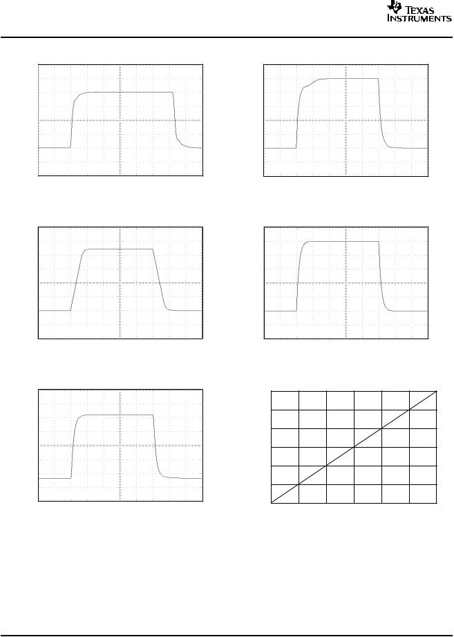
STEP RESPONSE
G = 20
Output Voltage (50mV/div)
VSENSE = 90mV to 100mV
Time (2 s/div)
Figure 14.
STEP RESPONSE
G = 50
Output Voltage (1V/div)
VSENSE = 10mV to 100mV
Time (5 s/div)
Figure 16.
STEP RESPONSE
G = 100
Output Voltage (2V/div)
VSENSE = 10mV to 100mV
Time (10 s/div)
Figure 18.
www.ti.com
STEP RESPONSE
G = 50
Output Voltage (100mV/div)
VSENSE = 10mV to 20mV
Time (5 s/div)
Figure 15.
STEP RESPONSE
G = 50
Output Voltage (100mV/div)
VSENSE = 90mV to 100mV
Time (5 s/div)
Figure 17.
COMPARATOR VOL vs ISINK
|
600 |
|
|
500 |
|
|
400 |
|
(mV) |
300 |
|
OL |
||
|
||
V |
|
|
|
200 |
|
|
100 |
|
|
0 |
0 |
1 |
2 |
3 |
4 |
5 |
6 |
ISINK (mA)
Figure 19.
8 |
Submit Documentation Feedback |
www.ti.com
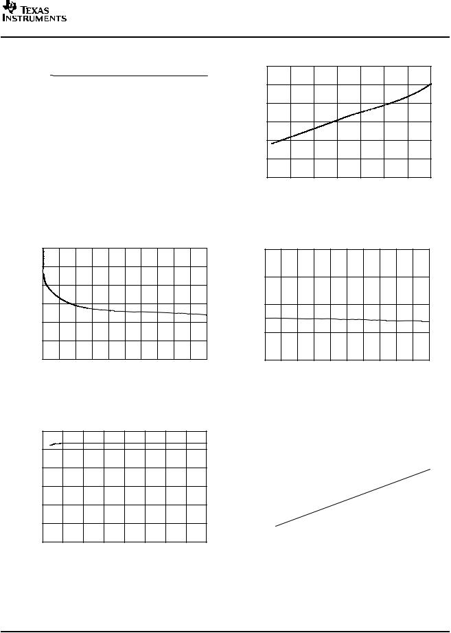
COMPARATOR TRIP POINT vs SUPPLY VOLTAGE
|
600 |
|
|
|
|
|
|
|
|
|
|
|
|
|
|
|
|
|
|
|
|
|
|
|
|
|
|
|
|
|
|
|
|
|
|
|
|
(mV) |
599 |
|
|
|
|
|
|
|
|
|
|
|
|
|
|
|
|
|
|
|
|
|
|
|
|
|
|
|
|
|
|
|
|
|
|
||
598 |
|
|
|
|
|
|
|
|
|
|
|
|
|
|
|
|
|
|
|
|
|
|
|
|
|
|
|
|
|
|
|
|
|
|
|
|
|
TripPoint |
597 |
|
|
|
|
|
|
|
|
|
|
|
|
|
|
|
|
|
|
|
|
|
|
|
|
|
|
|
|
|
|
|
|
|
|
||
595 |
|
|
|
|
|
|
|
|
|
|
|
|
|
|
|
|
|
|
Comparator |
596 |
|
|
|
|
|
|
|
|
|
|
|
|
|
|
|
|
|
594 |
|
|
|
|
|
|
|
|
|
|
|
|
|
|
|
|
|
|
|
|
|
|
|
|
|
|
|
|
|
|
|
|
|
|
|
|
|
|
593 |
|
|
|
|
|
|
|
|
|
|
|
|
|
|
|
|
|
|
|
|
|
|
|
|
|
|
|
|
|
|
|
|
|
|
|
|
|
592 |
|
|
|
|
|
|
|
|
|
|
|
|
|
|
|
|
|
|
|
|
|
|
|
|
|
|
|
|
|
|
|
|
|
|
|
|
|
591 |
|
|
|
|
|
|
|
|
|
|
|
|
|
|
|
|
|
|
|
|
|
|
|
|
|
|
|
|
|
|
|
|
|
|
|
|
|
590 |
|
|
|
|
|
|
|
|
|
|
|
|
|
|
|
|
|
|
|
4 |
6 |
8 |
10 |
|
|
|
|
16 |
18 |
|||||||
|
2 |
12 |
14 |
|||||||||||||||
Supply Voltage (V)
Figure 20.
COMPARATOR 1 PROPAGATION DELAY vs OVERDRIVE VOLTAGE
|
200 |
|
|
175 |
|
(ns) |
150 |
|
Delay |
||
|
||
Propagation |
125 |
|
100 |
||
|
||
|
75 |
|
|
50 |
0 |
20 |
40 |
60 |
80 |
100 |
120 |
140 |
160 |
180 |
200 |
|
|
|
Overdrive Voltage (mV) |
|
|
|
||||
Figure 22.
COMPARATOR RESET VOLTAGE vs SUPPLY VOLTAGE
|
1.2 |
|
1.0 |
(V) |
0.8 |
Voltage |
0.6 |
|
|
Reset |
0.4 |
|
|
|
0.2 |
|
0 |
2 |
4 |
6 |
8 |
10 |
12 |
14 |
16 |
18 |
Supply Voltage (V)
Figure 24.
INA206
INA207
INA208
SBOS360C – JUNE 2006 – REVISED JUNE 2007
COMPARATOR TRIP POINT vs TEMPERATURE
|
602 |
|
|
|
|
|
|
|
(mV) |
601 |
|
|
|
|
|
|
|
|
|
|
|
|
|
|
|
|
TripPoint |
600 |
|
|
|
|
|
|
|
599 |
|
|
|
|
|
|
|
|
Comparator |
598 |
|
|
|
|
|
|
|
597 |
|
|
|
|
|
|
|
|
|
|
|
|
|
|
|
|
|
|
596 |
|
|
|
|
|
|
|
|
–50 |
–25 |
0 |
25 |
50 |
75 |
100 |
125 |
Temperature (°C)
Figure 21.
COMPARATOR 2 PROPAGATION DELAY vs OVERDRIVE VOLTAGE
|
14 |
|
s) |
13 |
|
Delay( |
||
|
||
Propagation |
12 |
|
11 |
||
|
10 |
0 |
20 |
40 |
60 |
80 |
100 |
120 |
140 |
160 |
180 |
200 |
Overdrive Voltage (mV)
Figure 23.
COMPARATOR 1 PROPAGATION DELAY vs TEMPERATURE
|
300 |
|
|
|
|
|
|
|
|
|
|
|
|
|
|
|
|
|
|
|
|
|
|
|
|
|
|
|
|
|
|
|
|
(ns) |
275 |
|
|
|
|
|
|
|
|
|
|
|
|
|
|
|
|
|
|
|
|
|
|
|
|
|
|
|
|
|
|
||
250 |
|
|
|
|
|
|
|
|
|
|
|
|
|
|
|
|
|
|
|
|
|
|
|
|
|
|
|
|
|
|
|
||
Delay |
225 |
|
|
|
|
|
|
|
|
|
|
|
|
|
|
|
|
|
|
|
|
|
|
|
|
|
|
|
|
|
|
||
|
|
|
|
|
|
|
|
|
|
|
|
|
|
|
|
|
Propagation |
200 |
|
|
|
|
|
|
|
|
|
|
|
|
|
|
|
|
|
|
|
|
|
|
|
|
|
|
|
|
|
|
||
175 |
|
|
|
|
|
|
|
|
|
|
|
|
|
|
|
|
|
|
|
|
|
|
|
|
|
|
|
|
|
|
|
||
|
|
|
|
|
|
|
|
|
|
|
|
|
|
|
|
|
|
150 |
|
|
|
|
|
|
|
|
|
|
|
|
|
|
|
|
|
|
|
|
|
|
|
|
|
|
|
|
|
|
|
|
|
125 |
|
|
|
|
|
|
|
|
|
|
|
|
|
|
|
|
|
|
|
|
|
|
|
|
|
75 |
|
|
|
|
||
|
–50 |
–25 |
0 |
25 |
50 |
100 |
125 |
|||||||||
Temperature (°C)
Figure 25.
Submit Documentation Feedback |
9 |
 Loading...