


Texas Instruments BQ2000TPN-B5, BQ2000TPN-B4, BQ2000TSN-B5TR, BQ2000TSN-B5, BQ2000TSN-B4TR Datasheet
...Features
Safe management of fast charge for NiCd, NiMH, or LiIon battery packs
High-frequency switching controller for efficient and simple charger design
Pre-charge qualification for detecting shorted, damaged, or overheated cells
Fast-charge termination by ∆T/∆t minimum current (Li-Ion), maximum temperature, and maximum charge time
Selectable top-off mode for achieving maximum capacity in NiMH batteries
Programmable trickle-charge mode for reviving deeply discharged batteries and for postcharge maintenance
Built-in battery removal and insertion detection
Sleep mode for low power consumption
bq2000T
Programmable Multi-Chemistry
Fast-Charge Management IC
General Description
The bq2000T is a programmable, monolithic IC for fast-charge management of nickel cadmium (NiCd), nickel metal-hydride (NiMH), or lith- ium-ion (Li-Ion) batteries in singleor multi-chemistry applications. The bq2000T detects the battery chemistry and proceeds with the optimal charging and termination algorithms. This process eliminates undesirable undercharged or overcharged conditions and allows accurate and safe termination of fast charge.
Depending on the chemistry, the bq2000T provides a number of charge termination criteria:
Rate of temperature rise, ∆T/∆t (for NiCd and NiMH)
Minimum charging current (for Li-Ion)
Maximum temperature
Maximum charge time
For safety, the bq2000T inhibits fast charge until the battery voltage and temperature are within user-defined limits. If the battery voltage is below the low-voltage threshold, the bq2000T uses trickle-charge to condition the battery. For NiMH batteries, the bq2000T provides an optional top-off charge to maximize the battery capacity.
The integrated high-frequency comparator allows the bq2000T to be the basis for a complete, high-efficiency power-conversion circuit for both nickel-based and lithium-based chemistries.
Pin Connections
SNS |
1 |
8 |
MOD |
|
VSS |
2 |
7 |
VCC |
|
|
3 |
6 |
RC |
|
LED |
|
|||
BAT |
4 |
5 |
TS |
|
|
|
|
|
|
8-Pin DIP or Narrow SOIC or TSSOP
PN-2000.eps
SLUS149A–FEBRUARY 2000
Pin Names
SNS |
Current-sense input |
TS |
Temperature-sense |
||
VSS |
System ground |
|
input |
||
RC |
Timer-program input |
||||
|
|
Charge-status |
|||
LED |
|
VCC |
|
||
|
|
output |
Supply-voltage input |
||
BAT |
Battery-voltage |
MOD |
Modulation-control |
||
|
|
input |
|
output |
|
1
bq2000T
Pin Descriptions
SNS |
Current-sense input |
|
Enables the bq2000T to sense the battery |
|
current via the voltage developed on this pin |
|
by an external sense-resistor connected in |
|
series with the battery pack |
VSS |
System Ground |
|
Charge-status output |
LED |
|
|
Open-drain output that indicates the charg- |
|
ing status by turning on, turning off, or |
|
flashing an external LED |
BAT |
Battery-voltage input |
|
Battery-voltage sense input. A simple resistive |
|
divider, across the battery terminals, generates |
|
this input. |
TS |
Temperature-sense input |
RC |
Timer-program input |
|
RC input used to program the maximum |
|
charge-time, hold-off period, and trickle |
|
rate during the charge cycle, and to disable |
|
or enable top-off charge |
VCC |
Supply-voltage input |
MOD |
Modulation-control output |
|
Push-pull output that controls the charging |
|
current to the battery. MOD switches high |
|
to enable charging current to flow and low to |
|
inhibit chargingcurrent flow. |
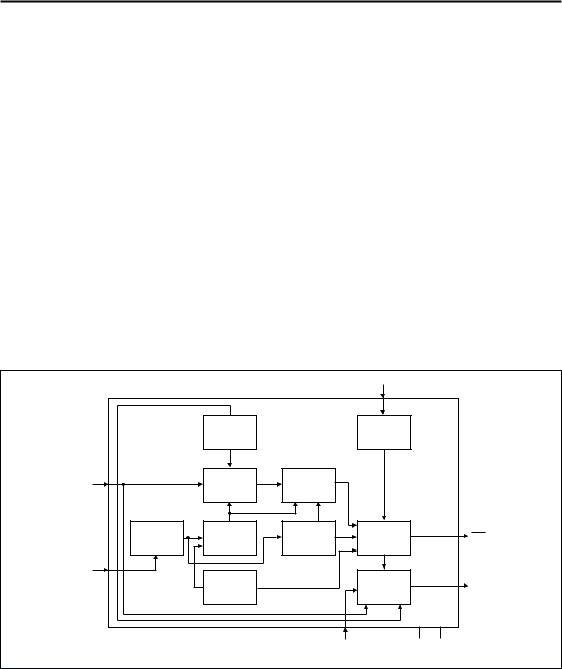
Functional Description
The bq2000T is a versatile, multi-chemistry batterycharge control device. See Figure 1 for a functional block diagram and Figure 2 for the state diagram.
Input for an external battery-temperature monitoring circuit. An external resistive divider network with a negative tempera- ture-coefficient thermistor sets the lower and upper temperature thresholds.
|
|
|
TS |
|
|
|
Voltage |
|
Voltage |
|
|
|
Reference |
|
Comparator |
|
|
BAT |
ADC |
∆T/∆t |
|
|
|
ALU |
|
|
|||
|
|
|
|
||
OSC |
Clock |
Timer |
Charge |
LED |
|
Phase |
|||||
Control |
|||||
|
Generator |
|
|
||
|
|
|
|
||
RC |
|
|
|
|
|
|
Internal |
|
Voltage |
MOD |
|
|
OSC |
|
Comparator |
||
|
|
|
|||
|
|
SNS |
VCC |
VSS |
|
|
|
|
|
BD2000T.eps |
Figure 1. Functional Block Diagram
2

|
|
|
|
|
|
|
bq2000T |
|
|
|
|
4.0V < VCC < 6.0V |
|
|
|
|
|
|
|
Charge |
|
|
|
|
|
|
|
Initialization |
|
|
|
|
|
|
VBAT < VSLP |
Battery Voltage |
VMCV < VBAT < VSLP |
|
|
|
Sleep |
|
|
|
|||
|
|
|
(checked at all times) |
|
|
||
|
Mode |
|
|
|
|
||
|
|
|
|
|
|
|
|
|
|
|
VSLP < VBAT < VCC |
|
|
|
|
|
|
|
|
VBAT < VMCV |
|
||
|
|
|
VTS > VHTF |
|
|
|
|
|
Charge |
|
VTS < VHTF |
Battery Temperature |
|
|
|
|
Suspended |
(checked at all times) |
|
|
|||
|
|
|
|
||||
|
|
|
|
|
|
||
|
|
|
VBAT < VLBAT or |
VLBAT < VBAT < VMCV and |
|
||
|
Battery |
|
VTS > VLTF |
|
VHTF < VTS < VLTF |
Current |
|
|
|
|
|
|
|
||
|
Conditioning |
|
|
|
Regulation |
||
|
|
|
VLBAT < VBAT < VMCV and |
∆T/∆t (after hold-off period), |
|
||
|
|
|
VHTF < VTS < VLTF |
or VTS |
< VTCO or |
Time < MTO |
|
|
|
|
|
|
Time = MTO |
||
|
|
|
|
|
and |
||
|
|
|
|
|
|
|
|
|
|
|
|
|
|
|
VBAT > VMCV |
VCC |
|
|
No |
|
|
|
|
Reset |
Maintenance |
|
Top-Off |
|
|
Voltage |
|
|
|
|
|
|
|||
|
Charge |
|
|
|
Regulation |
||
|
|
|
Selected? |
|
|||
|
|
|
|
|
|
|
|
|
|
|
|
Yes |
|
|
|
|
|
|
|
|
|
|
Current Taper |
|
|
|
|
|
|
|
or |
|
|
|
|
|
|
|
Time = MTO |
|
|
Time = MTO or |
|
VBAT > VMCV |
|
||
|
|
VTS < VTCO |
Top-Off |
|
|||
|
|
|
|
|
|
|
|
|
|
|
|
|
|
|
Done |
|
|
|
|
|
VBAT > VMCV |
|
|
|
|
|
VCC Reset or Battery Replacement or Capacity Depletion (Li-Ion) |
|
|||
|
|
|
|
|
|
|
SD2000T.eps |
Figure 2. State Diagram
3
bq2000T
Initiation and Charge Qualification
The bq2000T initiates a charge cycle when it detects
Application of power to VCC
Battery replacement
Exit from sleep mode
Capacity depletion (Li-Ion only)
Immediately following initiation, the IC enters a charge-qualification mode. The bq2000T charge qualification is based on battery voltage and temperature. If voltage on pin BAT is less than the internal threshold, VLBAT, the bq2000T enters the charge-pending state. This condition indicates the possiblility of a defective or shorted battery pack. In an attempt to revive a fully depleted pack, the bq2000T enables the MOD pin to trickle-charge at a rate of once every 1.0s. As explained in the section “Top-Off and Pulse-Trickle Charge,” the trickle pulse-width is user-selectable and is set by the value of the resistance connected to pin RC.
During this period, the LED pin blinks at a 1Hz rate, indicating the pending status of the charger.
Similarly, the bq2000T suspends fast charge if the battery temperature is outside the VLTF to VHTF range. (See Table 4.) For safety reasons, however, it disables the pulse trickle, in the case of a battery over-temperature condition (i.e., VTS < VHTF). Fast charge begins when the battery temperature and voltage are valid.
Battery Chemistry
The bq2000T detects the battery chemistry by monitoring the battery-voltage profile during fast charge. If the voltage on BAT input rises to the internal VMCV reference, the IC assumes a Li-Ion battery. Otherwise the bq2000T assumes NiCd/NiMH chemistry.
As shown in Figure 6, a resistor voltage-divider between the battery pack’s positive terminal and VSS scales the battery voltage measured at pin BAT. In a mixed-chemistry design, a common voltage-divider is used as long as the maximum charge voltage of the nickel-based pack is below that of the Li-Ion pack. Otherwise, different scaling is required.
Once the chemistry is determined, the bq2000T completes the fast charge with the appropriate charge algorithm (Table 1). The user can customize the algorithm by programming the device using an external resistor and a capacitor connected to the RC pin, as discussed in later sections.
NiCd and NiMH Batteries
Following qualification, the bq2000T fast-charges NiCd or NiMH batteries using a current-limited algorithm. During the fast-charge period, it monitors charge time, temperature, and voltage for adherence to the termination criteria. This monitoring is further explained in later sections. Following fast charge, the battery is topped off, if top-off is selected. The charging cycle ends
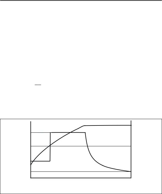
IMAX
Current
Trickle
IMIN
Qualification
VMCV
Voltage
Fast Charge
VLBAT
Phase 1 |
|
Phase 2 |
|
Current |
Voltage |
|
|
Time
GR2000CA.eps
Figure 3. Lithium-Ion Charge Algorithm
4

bq2000T
|
|
Table 1. Charge Algorithm |
|
|
|
|
|
Battery Chemistry |
|
Charge Algorithm |
|
|
1. |
Charge qualification |
|
|
2. |
Trickle charge, if required |
|
NiCd or NiMH |
3. |
Fast charge (constant current) |
|
4. |
Charge termination (∆T/∆t, time) |
||
|
|||
|
5. |
Top-off (optional) |
|
|
6. |
Trickle charge |
|
|
1. |
Charge qualification |
|
Li-Ion |
2. |
Trickle charge, if required |
|
3. |
Two-step fast charge (constant current followed by constant voltage) |
||
|
|||
|
4. |
Charge termination (minimum current, time) |
with a trickle maintenance-charge that continues as long as the voltage on pin BAT remains below VMCV.
charge. This feature provides the additional charge time required for Li-Ion cells.
Lithium-Ion Batteries
The bq2000T uses a two-phase fast-charge algorithm for Li-Ion batteries (Figure 3). In phase one, the bq2000T regulates constant current until VBAT rises to VMCV. The bq2000T then moves to phase two, regulates the battery with constant voltage of VMCV, and terminates when the charging current falls below the IMIN threshold. A new charge cycle is started if the cell voltage falls below the VRCH threshold.
During the current-regulation phase, the bq2000T monitors charge time, battery temperature, and battery voltage for adherence to the termination criteria. During the final constant-voltage stage, in addition to the charge time and temperature, it monitors the charge current as a termination criterion. There is no post-charge maintenance mode for Li-Ion batteries.
Charge Termination
Maximum Charge Time (NiCD, NiMH, and
Li-Ion)
The bq2000T sets the maximum charge-time through pin RC. With the proper selection of external resistor and capacitor, various time-out values may be achieved. Figure 4 shows a typical connection.
The following equation shows the relationship between the RMTO and CMTO values and the maximum charge time (MTO) for the bq2000T:
MTO = RMTO CMTO 35,988
MTO is measured in minutes, RMTO in ohms, and CMTO in farads. (Note: RMTO and CMTO values also determine other features of the device. See Tables 2 and 3 for details.)
For Li-Ion cells, the bq2000T resets the MTO when the battery reaches the constant-voltage phase of the
Maximum Temperature (NiCd, NiMH, Li-Ion)
A negative-coefficient thermistor, referenced to VSS and placed in thermal contact with the battery, may be used as a temperature-sensing device. Figure 5 shows a typical temperature-sensing circuit.
During fast charge, the bq2000T compares the battery temperature to an internal high-temperature cutoff threshold, VTCO. As shown in Table 4, high-temperature termination occurs when voltage at pin TS is less than this threshold.
∆T/∆t (NiCd, NiMH)
When fast charging, the bq2000T monitors the voltage
at pin TS for rate of temperature change detection, ∆T/∆t. The bq2000T samples the voltage at the TS pin
every 16s and compares it to the value measured 2 samples earlier. This feature terminates fast charge if this voltage declines at a rate of
VCC V  161 Min
Figure 5 shows a typical connection diagram.
Minimum Current (Li-Ion Only)
The bq2000T monitors the charging current during the voltage-regulation phase of Li-Ion batteries. Fast charge is terminated when the current is tapered off to 7% of the maximum charging current. Please note that this threshold is different for the bq2000.
Initial Hold-Off Period
The values of the external resistor and capacitor connected to pin RC set the initial hold-off period. During this period, the bq2000T avoids early termination by disabling the ∆T/∆t feature. This period is fixed at the
5
 Loading...