


Telex
Operating Instructions
RadioComTM
Wireless IFB
TT-16
16 Channel Transmitter
TR-16
16 Channel Receiver
INTRODUCTION
WHAT IS THE TELEX WIRELESS IFB SYSTEM?
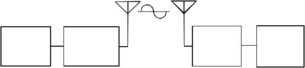
Transmitter: The transmitter generates and amplifies a RF (Radio Frequency) carrier signal, modulates this carrier with the microphone signal, and radiates the modulated RF carrier.
Receiver: The FM VHF receiver is tuned to the frequency of the transmitter. The receiver picks up the radiated RF signal from the transmitter through the antenna and converts the RF signal into audio voltages for use with an earphone, headphone, button receiver, neckloop, etc. The receiver frequency must be matched to the transmitter frequency.
WHAT FREQUENCY BAND DOES THE TELEX SYSTEM OPERATE IN?
The Telex Systems feature a synthesized transmitter and a synthesized receiver operating in the VHF Band between 64-68 MHz. See Table 1 for standard frequencies available.
Each transmitter channel can be utilized by any number of receivers in any given area. Up to five simultaneous systems can be used in a given area.
ANT. ANT.
|
|
RF CARRIER |
|
|
|
|
SIGNAL |
|
|
SOUND |
TRANSMITTER |
FM |
EARPHONE |
|
SOURCE |
RECEIVER |
|||
|
|
Figure 1
Block Diagram of Typical Wireless IFB System
-1-

OFTEN ASKED QUESTIONS
Question: Can more than one system be used simultaneously?
Answer: Yes but never on the same frequency. You will need to have different frequencies for every receiver/transmitter combination.
Question: Is the system more sensitive in any one particular direction?
Answer: No, the transmitter’s antenna radiates equally in all directions, but the signal is attenuated by your body, walls or other surrounding objects. The receiving antenna is essentially sensitive in all directions as well.
Question: Can the receiver receive other transmissions when the transmitter is turned off?
Answer: Yes it can. Telex systems operate in the VHF Band between 64-68 MHz. However, it is not susceptible to radio wave skip, CB’ers or standard FM radio transmissions. It is on TV Broadcast channels 3 and 4. So it is best to use the channels in your system that are not on the TV broadcast channel in your area. See Table 1.
The frequency your system operates on is computer selected for least interference, but there is no such thing as a 100% clear channel all the time.
If the system is going to be used in a permanent fixed location, it should operate interference free until such a time or date when someone else begins using the same frequency.
If the system is going to be moving among various locations, you may run into occasional frequency conflicts.
Whenever the system is in use, the transmitter should be left on to prevent the receiver from picking up outside interference.
Question: What is E.D.R.?
Answer: E.D.R. stands for enhanced Dynamic Range (companded) audio. E.D.R. improves the sig- nal-to-noise ratio providing much better audio quality.
Question: Can the TT-16 and TR-16 be used with existing TR-34 and TT-44 products.
Answer: Yes, as long as the E.D.R. feature is disabled on the TT-16 and TR-16.
AVAILABLE FREQUENCIES
Channel |
Freq. in MHz |
Broadcast TV |
|
|
Channel |
1 |
64.5 |
3 |
|
|
|
2 |
64.7 |
3 |
|
|
|
3 |
64.9 |
3 |
|
|
|
4 |
65.1 |
3 |
|
|
|
5 |
65.3 |
3 |
|
|
|
6 |
65.5 |
3 |
|
|
|
7 |
65.7 |
3 |
|
|
|
8 |
65.9 |
3 |
|
|
|
A |
66.1 |
4 |
|
|
|
B |
66.3 |
4 |
|
|
|
C |
66.5 |
4 |
|
|
|
D |
66.7 |
4 |
|
|
|
E |
66.9 |
4 |
|
|
|
F |
67.1 |
4 |
|
|
|
G |
67.3 |
4 |
|
|
|
H |
67.5 |
4 |
|
|
|
|
|
|
Table 1
Frequencies Available
-2-
TR-16 SYNTHESIZED
RECEIVER
General Description TR-16
The Telex TR-16 Receiver is a component of a system which operates on sixteen (16) user selectable channels in the 64 to 68 MHz frequency band. The receivers are designed to be used with the Telex TT-16 Transmitter.
Operating Features
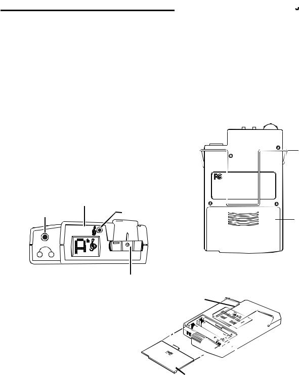
Volume OFF/ON Control: This thumbwheel control serves as both an off/on switch and as a volume control. The receiver is turned off when the control is in the extreme counter-clockwise position, when viewed from the rear, and the volume is loudest when the control is in the extreme clockwise position.
SET
SWITCH
BUTTON
HEADPHONE JACK TREBLE CONTROL
SET
 E.D.R.
Treble Control: A push button treble control is provided to enhance higher frequency audio when the button is engaged, indicated by  .
.
Headphone Jack: The receiver jack accepts a 0.140-inch (3.5 mm) diameter miniature plug. A variety of earsets or headphones can be plugged into this jack for listening.
Belt Clip: The belt clip supplied is detachable by spreading the wire apart at the tops and removing one side of the clip form the case and then the other.
BELT CLIP
TELEX COMMUNICATIONS, INC.

 MODEL TR-16
IC: 1321A-TR16
This device complies with part 15 of the FCC rules. Operation is subject to the following two conditions: (1) This device may not cause harmful interference, and (2) this device must accept any interference received, including interference that may cause undesired operation.
Made in U.S.A. |
S.N.: 1001 |
BATTERY
COMPARTMENT
VOLUME OFF/ON CONTROL
BELT CLIP

 BATTERY
ORIENTATION
BATTERY COMPARTMENT COVER
Figure 3
Operating Features TR-16
-3-
SPECIFICATIONS |
|
|
TR-16 16 Channel Synthesized Receiver |
|
|
Temperature Range.................................................................... |
|
32 to 122 degrees F/0 to +50 degrees C |
Supply Voltage ............................................................................................... |
|
2-3 Volts, (2) AA Batteries |
Battery Life.................................................................................................................... |
|
20 Hrs - Alkaline |
|
|
16 Hrs - NimH |
|
|
8 Hrs - NiCad |
Frequency Response .................................................................................................... |
|
100-10 kHz ±3 dB |
Sensitivity (12 dB SINAD @ 66.1 MHz)................................................................................ |
|
1µ V max. |
Distortion ............................................................................................................................... |
|
less than 2% |
Audio Output @ 10% Distortion |
8 ohm |
32 ohm |
Battery Input |
||
Voltage |
|
|
2.0 V |
15 mW |
10 mW |
3.0 V |
80 mW |
50 mW |
Controls and Connections................................................................................. |
|
Volume OFF/ON Switch; |
|
Treble Control Switch; Channel Selection Switch |
|
|
|
Audio Output Jack |
TT-16 SYNTHESIZED
TRANSMITTER
General Description
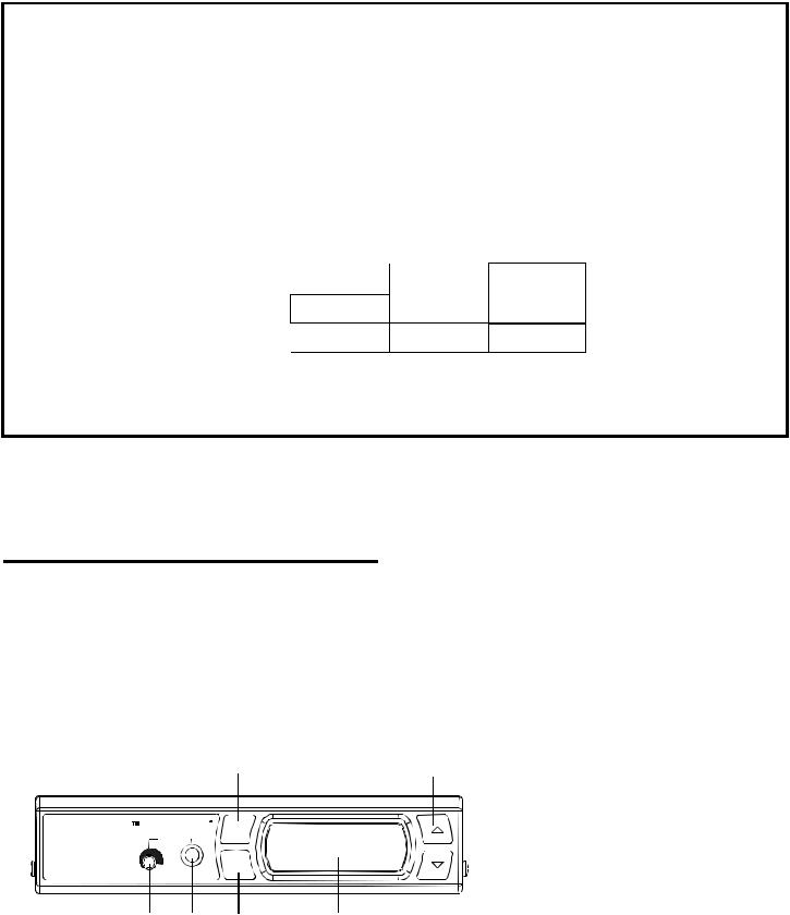
The Telex TT-16 is a base station transmitter which operates in the 64-68 MHz band and accepts a wide range of audio input levels.
Operating Features
|
|
|
|
|
|
TT-16 Front Panel |
|
|
1 |
|
6 |
1. |
Power Button (Must be held in for 1 |
|
|
|
|
second to turn off.) |
||
|
|
|
|
|
2. |
Headphone volume adjustment |
RadioCom |
Telex |
power |
|
|
3. Headphone Monitoring Jack |
|
|
Monitor |
|
|
|
|
|
TT-16 |
|
set |
|
|
4. SET Button |
|
WIRELESS IFB TRANSMITTER |
|
|
|
|
|
|
|
|
|
|
|
5. |
Back Lit LCD Display |
2 |
3 |
4 |
5 |
|
6. |
UP and DOWN Adjustment Buttons |
|
|
|
||||
Figure 4a
Operating Features TT-16 Front Panel
-4-
 Loading...