


C-2002

Model C-2002
Radio Control Console
Technical Manual
November 8, 2005 P.N. 803548
REV D


Remote Control Console i
Table of Contents
1 INTRODUCTION...............................................................................................................................................1
2 CONTROLS AND INDICATORS.....................................................................................................................2
2.1 FRONT PANEL.................................................................................................................................................2
2.1.1 Common Controls and Indicators .........................................................................................................2
2.2 REAR PANEL CONNECTIONS ........................................................................................................................... 3
2.2.1 Rear Panel Ports ...................................................................................................................................3
3 OPERATION.......................................................................................................................................................5
3.1 SELECTING A LINE ..........................................................................................................................................5
3.2 RELEASING A LINE ..........................................................................................................................................5
3.3 MUTING A LINE...............................................................................................................................................5
3.4 SELECTING A FREQUENCY (F-TONE)...............................................................................................................5
3.5 SUPERVISORY CONTROL .................................................................................................................................5
3.6 SENDING ALERT TONES ..................................................................................................................................5
3.7 VOLUME CONTROL.........................................................................................................................................5
4 LINE SETUP AND DESCRIPTION.................................................................................................................6
4.1 INTRODUCTION/DEFAULTS....................................................................................................................6
4.2 FEATURE DESCRIPTION ..........................................................................................................................6
4.2.1 Crossmute..............................................................................................................................................6
4.2.2 Supervisor Function ..............................................................................................................................7
4.2.3 Relay Contact Closure For Local Control ............................................................................................7
4.2.4 Two-Wire/Four-Wire Mode...................................................................................................................7
4.2.5 RX Side Settings.....................................................................................................................................7
4.2.6 TX Side Settings.....................................................................................................................................8
4.2.7 Transmit Monitor...................................................................................................................................8
4.3 LEVEL ADJUSTMENTS..................................................................................................................................... 9
4.3.1 Transmit Side Adjustments ....................................................................................................................9
4.3.2 Transmit Monitor Setup.........................................................................................................................9
4.3.3 RX Level Adjustment..............................................................................................................................9
5 HARDWARE OVERVIEW .............................................................................................................................10
5.1 C-2002 CONSOLE .........................................................................................................................................10
5.1.1 Main PCB............................................................................................................................................10
5.1.1.1 Line Interface......................................................................................................................................................... 10
5.1.2 Keypad PCB ........................................................................................................................................ 10
5.1.3 Display.................................................................................................................................................10
6 THEORY OF OPERATION............................................................................................................................11
6.1 MICROPHONE INPUT PATHS.......................................................................................................................... 11
6.2 AUDIO OUTPUT PATHS .................................................................................................................................11
6.3 LINE RECEIVE PATHS LINE (ONE/TWO)........................................................................................................11
6.4 SYSTEM CLOCK GENERATION ......................................................................................................................12
6.5 NON-VOLATILE MEMORY (EEPROM)......................................................................................................... 12
6.6 USER I/O ......................................................................................................................................................12
6.7 CLONE MODE SERIAL PORT..........................................................................................................................12
6.8 POWER REGULATION AND RESET CONTROL .................................................................................................12
7 SETUP MODE...................................................................................................................................................13
7.1 TECH MODE .................................................................................................................................................13
7.1.1 Erasing all settings..............................................................................................................................13
7.1.2 Resetting the PIN Number...................................................................................................................13
7.1.3 Opening Display Menu........................................................................................................................14
7.1.4 Button Activated Setup Modes.............................................................................................................15
7.2 OPENING MENU ............................................................................................................................................ 15

ii Vega’s C-2002
7.3 LEVEL MENU SCREEN ..................................................................................................................................15
7.3.1 Menu 1 - Line Level Settings ...............................................................................................................16
7.3.1.1 RX Input Level Screen .......................................................................................................................................... 16
7.3.1.2 LAM Programming Screen.................................................................................................................................... 16
7.3.1.2.1 LAM Duration After Release screen.............................................................................................................. 16
7.3.1.2.2 LAM Trigger Level Screen ............................................................................................................................ 16
7.3.1.3 Mute Button Level Screen..................................................................................................................................... 16
7.3.1.3.1 Mute Button Level Screen.............................................................................................................................. 17
7.3.2 Main Level Settings..............................................................................................................................17
7.3.2.1 Microphones Screen .............................................................................................................................................. 17
7.3.2.1.1 Desk microphone Preamp Gain Screen .......................................................................................................... 17
7.3.2.1.2 Handset Preamp Gain Screen......................................................................................................................... 17
7.3.2.1.3 Aux Preamp Gain Screen ............................................................................................................................... 17
7.3.2.2 Speaker Level Setting............................................................................................................................................ 17
7.3.2.2.1 Minimum Speaker Level................................................................................................................................ 17
7.3.2.3 Output Level Screens............................................................................................................................................. 18
7.3.2.3.1 TX Output Level ............................................................................................................................................ 18
7.4 SYSTEM SETTINGS SCREEN...........................................................................................................................18
7.4.1 Clock Settings Screen ..........................................................................................................................18
7.4.1.1 Clock Edit Screen .................................................................................................................................................. 18
7.4.1.1.1 Clock Hours Screen........................................................................................................................................ 18
7.4.1.1.2 Clock Minutes Screen .................................................................................................................................... 18
7.4.2 Dump Function....................................................................................................................................19
7.4.2.1 Dump Error Screen................................................................................................................................................ 19
7.4.3 Menu 2 System Setup Screen ...............................................................................................................19
7.4.3.1 Tone Settings Screen ............................................................................................................................................. 19
7.4.3.1.1 DTMF Settings............................................................................................................................................... 19
7.4.3.1.1.1 First DTMF Settings Screen ................................................................................................................... 19
7.4.3.1.1.2 Next DTMF digit Settings Screen.......................................................................................................... 20
7.4.3.1.1.3 DTMF Keypad Enable/Disable............................................................................................................... 20
7.4.3.1.1.4 Enable/Disable PTT tones with DTMF................................................................................................... 20
7.4.3.1.1.5 Select Call Timer Duration Setup ........................................................................................................... 20
7.4.3.1.2 Single Tone Settings....................................................................................................................................... 21
7.4.3.1.2.1 Guard/Function/Hold Level Settings ...................................................................................................... 21
7.4.3.1.2.2 Guard/Hold Frequencies ......................................................................................................................... 22
7.4.3.1.2.3 Guard/Hold Duration’s ........................................................................................................................... 22
7.4.3.1.3 Test Tone Screen............................................................................................................................................ 22
7.4.5.2 AUX Input Enable ................................................................................................................................................. 22
7.4.4 Menu 3 System Setup Screen ...............................................................................................................23
7.4.4.1 PIN Number Entry................................................................................................................................................. 23
7.4.4.2 TX Delay Setup ..................................................................................................................................................... 23
7.4.5 Menu 4 System Setup Screen ...............................................................................................................23
7.4.5.1 Unselect Audio Mute............................................................................................................................................. 23
7.4.5.2 Duplex Enable ....................................................................................................................................................... 24
7.4.6 Menu 5 System Setup Screen ...............................................................................................................24
7.4.6.1 MicAGC Function ................................................................................................................................................. 24
7.4.6.2 Handset installed.................................................................................................................................................... 24
7.4.7 Menu 6 System Setup Screen ...............................................................................................................24
7.4.7.1 Parallel Console UP-Date Function....................................................................................................................... 24
7.5 ALPHANUMERIC FUNCTION-LINE SETUP ......................................................................................................24
7.5.1 Line/F-Tone Selection Screen..............................................................................................................25
7.5.1.1 Line Alphanumeric Selection Screen..................................................................................................................... 25
7.5.1.1.1 Line Alphanumeric Programming Screen ...................................................................................................... 25
7.6 LINE TONE/LOCAL SCREEN ..........................................................................................................................26
7.6.1 Enable/Disable the Line ......................................................................................................................26
7.6.2 Tone or Local Control.........................................................................................................................26
7.6.3 Crossmute Setup ..................................................................................................................................26
7.6.4 Squelch Setup.......................................................................................................................................26
7.6.5 TX Monitor Enable/Disable.................................................................................................................26
7.6.6 Automatic Gain Control (AGC) Enable/Disable.................................................................................27
7.6.7 TX Enable/Disable per Line ................................................................................................................27
7.6.8 Forced Unselect of a Line....................................................................................................................27
7.6.9 DTMF ANI Decode Enable .................................................................................................................27

Remote Control Console iii
MUTE BUTTON .............................................................................................................................................27
7.7
7.7.1 Per line Mute button Setup..................................................................................................................27
7.7.2 Incoming Select Call DTMF String Setup ...........................................................................................28
7.8 FUNCTION TONE PARAMETER SCREEN .........................................................................................................28
7.8.1 Function Tone Enabled/Disable..........................................................................................................28
7.8.2 Function Tone Setup............................................................................................................................28
7.8.3 Frequency Programming Screen.........................................................................................................28
7.8.4 Duration Display Screen .....................................................................................................................28
7.8.5 Dual Function Tone mode Screen .......................................................................................................29
7.9 SUPERVISOR ENABLE ................................................................................................................................... 29
7.10 ALERT PROGRAMMING .................................................................................................................................29
7.10.1 Cadence Level Selection......................................................................................................................29
7.10.2 Cadence Frequency Selection..............................................................................................................29
7.11 MONITOR PROGRAMMING SCREEN...............................................................................................................30
7.11.1 Monitor Characteristic Selection.........................................................................................................30
7.11.1.1 Monitor Frequency .............................................................................................................................................. 30
7.11.1.2 Monitor Duration................................................................................................................................................. 30
7.11.1.3 Monitor Level...................................................................................................................................................... 30
8 TECHNICAL DOCUMENTATION...............................................................................................................34
8.1 C-2002 MAIN BOARD, P/N 879583 .............................................................................................................34
8.1.1 Schematic.............................................................................................................................................34
8.1.2 Bill of Material, component layout......................................................................................................34
8.2 C-2002 KEYPAD BOARD, P.N. 879573 ........................................................................................................34
8.2.1 Schematic.............................................................................................................................................34
8.2.2 Bill of Material, component layout......................................................................................................34
8.3 C-2002 TOP ASSEMBLY, P.N. 879592 .........................................................................................................34
9 WARRANTY, SERVICE, REPAIR, AND COMMENTS.............................................................................35
10 SPECIFICATIONS.......................................................................................................................................36

iv Vega’s C-2002
Table of Figures
Figure 1 Front Panel Diagram .....................................................................................................................2
Figure 2 Rear Panel Diagram.......................................................................................................................3
Figure 3 Rear Panel Pinout ..........................................................................................................................4
Figure 4 Line Connector Pin Out.................................................................................................................6
Figure 5 Crossmute Function example........................................................................................................6
Figure 6 Supervisor Function Example.......................................................................................................7
Figure 7 Master/Slave Console Configuration............................................................................................8
C-2002 DEFAULT SHIPPING CONFIGURATION:
The C-2002HS is shipped from the factory in the following state:
1) 4 Wire Mode
2) Full Duplex
3) TX Monitor Disabled
4) 600 Ohm TX output impedance
5) 600 Ohm RX input impedance

Remote Control Console 1
1 Introduction
The model C-2002 is a full-featured Two-Line, multi-format, and self-contained desktop radio control console. Its
sleek and modern look will compliment any surroundings.
The C-2002 is a Digital Signal Processor (DSP) based design, allowing easy field programmability using the DTMF
and soft keypads on the front of the console. Unlike other manufacturers’ equipment, no additional software is
required to program the C-2002 console. Modifications and enhancements can generally be made via a software
change only. If the user determines they require a special feature enhancement, please contact the Vega Sales
Department for cost and feasibility.
Initial Line level adjustments are made via potentiometers allowing for ease of installation. Should additional
adjustments be required, they can be made in the programming mode. AGC on receive and microphone audio paths
help stabilize line level adjustments.
The C-2002’s modular design offers control of one base station, along with selection of 99 frequencies. The line
interface offers crossmute capability and squelch control feature eliminating the unwanted noise that is generally
associated when monitoring a line.
The C-2002 will accommodate a desk microphone along with a handset (or headset) as indicated on the side of the
C-2002 console. In addition to the external microphone options, a built in panel microphone is available by pressing
the PTT on the front of the panel. When a PTT occurs from any of the three microphones, the others will mute so
as not to pick-up unnecessary ambient noise during transmission. When the handset is enabled and taken off hook
the receive audio is transferred to the earpiece.
The console is normally used in conjunction with a matching Vega 223 Series (or equivalent) tone-remote panel
located at the base station. The console is compatible with Motorola, MA/ComNet Ericsson/GE, and other toneremote control systems employing the industry-standard sequential tone-control format.
The console is connected to the mating panels by means of shielded voice-grade or better leased or private lines
(including microwave circuits). Metallic or DC continuity is not required.
2 Vega’s C-2002
S
M
L
L
2 Controls and Indicators
C-2002
Vu Muter 11:08A
Ln1-Fn2 Ln2-Fn8
A
3
->
DEF
B
6
<-
MNO
C
9
<sp>
WXYZ
D
#
Enter
LINE 1 LINE 2
RLS SE
MON
F2 F1
F3
F4 Alert
F5 F6
F7
F8
Mute RLS
IC
SUP
Chan
ALT
SE
Transmit
PQR
GHI
*
1
4
7
Mute
ABC
JKL
TUV
0
2
5
8
VOLUME
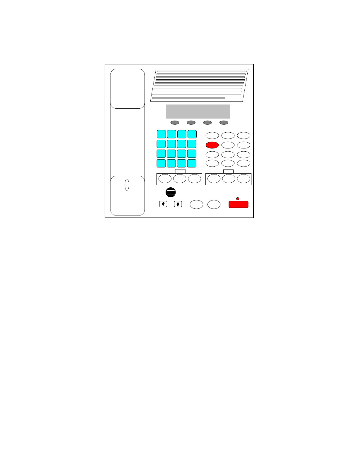
Figure 1 Front Panel Diagram
2.1 Front Panel
Figure 1 shows a view of the Front panel. The Front panel contains the user I/O. It features a Volume control,
intercom and monitor functions, panel PTT with indicator, built in panel microphone, per line Select, Release and
Mute functions, DTMF keypad, Supervisory, Alert, Channel and ALT functions used with the F1-F8 Function Tone
selection. The C-2002 is programmed from the front panel using the four gray soft keys located below the Vacuum
Florescent LCD display provides channel/numeric indication, clock and audio-level meter.
2.1.1 Common Controls and Indicators
VU Meter: Displays Selected receive and Microphone audio bus levels. This meter is shown on the top line of the
display and utilizes the first 12 display elements from the upper left.
Program 1-4: Are used as “soft” programming buttons when in the tech mode. These buttons will have different
functions depending on the action required. The bottom line of the display will show their respective functions.
DTMF Keypad: The DTMF keypad is used for transmitting DTMF digits, selecting frequencies for tone control in
tech mode (section 6), and entering alphanumeric strings for line/function tone combinations.
Function Buttons F1-F8: When a function tone button is pressed, a guard tone and function tone burst is sent out.
No hold tone is associated with the changing of the function tone. When one of the function tones is selected it will
light to indicate which function tone is chosen, a function tone shall remain selected until the operator changes the
setting. The console will power up with the last selected line and function tone pair selected.
Supervisory button: The SUP button allows one console operator to disable any other console, which is connected
to the supervised line. The Red LED is on during supervisory and blinking when being supervised
Alert button: When pressed, a alert tone plus key–up tones will be sent to all Selected lines.
Channel button: Used to change selected line F-tone frequency via the DTMF keypad.
ALT button: Used as a Alternate or Shift function for F1-8 and Alert tones.
Remote Control Console 3
A
Line Buttons LN1-LN2: Three buttons are available for each Line, SELect, RLS (Release) and Mute.
SELect button: When the SEL buttons is pressed that line enters the Select mode
Select LED: The Red LED under each LNx SEL Button indicates if the line is selected for transmit audio.
RLS button: The RLS button is used to release a selected line.
RLS LED: The blinking Red LED under each LNx RLS Button indicates receive audio activity on that line.
Mute button: The Mute button is used if RX audio from that line is not to be monitored in the speaker.
Mute LED: The steady Red LED under each LNx Mute Button indicates if the line is muted from receive
audio monitoring. A blinking LED indicates a external cross-mute.
Volume Control: Adjusts the receive speaker audio and handset earpiece level of the receive inputs of the line
interfaces. A minimum volume level can be set in tech-mode, so that the console operator cannot turn the speaker
volume to zero. When adjusting the level up or down, the display shows the selected level on a relative scale.
Monitor: When the Monitor button is pressed a Monitor tone burst is sent out on the selected line. The Monitor
tone burst consists of a guard tone and function tone of 2050Hz. An LED indication lights for the duration of the
tone burst.
Intercom (IC): When the Intercom button is pressed and held down the C-2002 shall transmit audio without
activating the tone generator. Intercom is considered a PTT operation with the tone generator disabled.
Panel PTT Pushbutton: When pressed, audio from the panel microphone plus key–up tones will be sent to all
Selected lines.
Transmit LED: This LED lights when any PTT source is depressed keying up the console. It will also blink if a
2175 Hz tone is detected on the selected TX audio lines. This would indicate to the operator that another console is
currently transmitting on one of the selected channels.
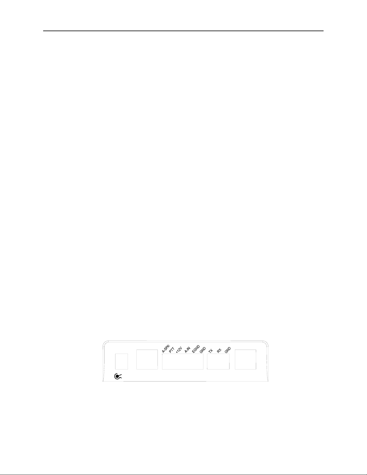
2.2 Rear Panel Connections
Figure 2 shows drawing of the rear panel of the C-2002. Each of the ports shown is discussed in detail in the
following section.
2.2.1 Rear Panel Ports
Power Jack: The left most jack on the C-2002 is the Power Jack. The power supply that is included with the unit
plugs in to this location. It is a standard 2.5mm center positive plug and requires at least 12V to operate correctly.
+12
POWER
+12
GND
LINE
1
UX
PORT
DATA
PORT
LINE
2
Figure 2 Rear Panel Diagram
4 Vega’s C-2002
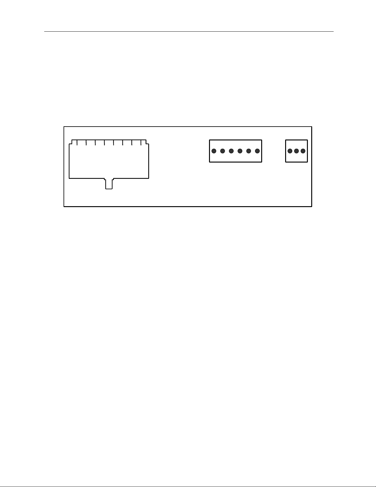
Line Port: The C-2002 is equipped with two single line jacks. The connector is a standard eight pin RJ-45. The
pinout of the connector appears in Figure 3. The numbering of the pins is shown in Figure 3 for reference. In
addition to the standard RX and TX pin pairs, the unit also can be supervised and supports cross mute functions.
Pins 7 and 8 of the Line connector can be used as a form C closure relay for local control. Pins 7 and 8 form the
closure during any PTT operation. An internal resistor makes an external connection to ground un-necessary, and
can be removed to remove ground from the closure path.
Auxiliary Audio Input: The external 6 pin terminal block provides an Audio Input (1), PTT (2), and GND (6)
line. Pulling PTT to ground activates the Audio Input line for transmitting audio from an external source. This
input is a high impedance capacitance coupled input.
Auxiliary Speaker: Pin 1 of the AUX Port is a capacitance coupled low impedance output that can be used to
drive an external speaker amplifier. Output level is controlled by the front panel volume control.
1 2 3 4 5 6 7 8
1) Cross Mute I/O
2) Supervisor I/O
3) RX +
4) TX +/(RX+2W)
5) TX -/(RX - 2W)
6) RX -
7) Local
8) GND/Local
1 2 3 4 5 6
1) RX Audio 2) PTT
3) +12V 4) Aux Audio In
5) Earth GND 6) Sig GND
1 2 3
1) TXD
2) RXD
3) GND
Rear Panel Connector Pinouts
Figure 3 Rear Panel Pinout
Battery backup: The +12V power input on the AUX Port is used for battery backup and is a diode-protected
input.
Earth Ground: The Earth ground connection on the AUX Port MUST be connected for proper operation. It
provides a path for any external noise to be shunted to.
Data port: This port is a 0 to 10V asynchronous port used for cloning one C-2002 to another. The cable is not
supplied but the connector is. To connect two units, RX on one console should be connected to TX of the other
console. Ground is connected straight through. This is a non-standard serial port used only for the C-2002 cloning
function.

Remote Control Console 5
3 Operation
3.1 Selecting a line
Selection of a line for transmit occurs when the “SEL” button is pressed and the LED under the switch lights, to
transmit on both lines press the “ALT” button then the “SEL” button of the opposite line.
3.2 Releasing a line
To release a selected line from transmit press the “RLS” button for the selected line. If the “RLS” button LED is
blinking RX audio was present on the line during the last 10 seconds or the time preset in tech-mode.
3.3 Muting a line
To mute a particular lines RX audio from the speaker press the “Mute” button. The mute button can be configured
for both latched or timed operation. If the “Mute” button LED is blinking a parallel console is transmitting on that
line and the console is being muted to reduce feedback squeal.
3.4 Selecting a frequency (F-Tone)
Selection of a F-tone can be accomplished in different ways, with a line selected simply press the desired F-tone
(F1-F8) and the associated Line and F-tone alphanumeric will be displayed on the second line of the display, if F9F16 are desired press the “ALT” button then the F-tone required (ALT + F3=F11).
The “Chan” button along with the DTMF keypad can also be used to change a F-tone, with a line selected simply
press “Chan” + “05” to set F5 for the selected line, “Chan” + “12” to set F12.
When both lines are selected any of the above methods will change the F-tone for both lines, to change only one of
the lines F-tone when in a group mode, simply hold down the desired lines “SEL” button and perform any of the
above methods.
3.5 Supervisory control
If supervisory control of a line is required, simply press the “SUP” button and all parallel consoles will be locked
out from use of this line, parallel consoles will display a blinking LED under the “SUP” button if they select a
supervised line. When completed simply press the “SUP” button again to release control of the line, now all
consoles will have use of the line for transmit.
3.6 Sending Alert tones
With a line selected, simply press the “Alert” button to generate an alert tone. If programmed in tech-mode the
“ALT” + “Alert” can be used to generate a different alert tone.
3.7 Volume Control
Holding down the selected line button and scrolling the volume meter on the display with the UP/DOWN volume
control button can adjust speaker volume.
Earpiece audio can be adjusted using the UP/DOWN volume control with the handset off-hook.
6 Vega’s C-2002
4 Line Setup and Description
4.1 INTRODUCTION/DEFAULTS
1 2 3 4 5 6 7 8 1) Cro s s Mute I/O
2) Supervisor I/O
3) RX +
4) TX +/ (RX + 2W)
5) TX -/ (RX - 2W)
6) RX -
7) Local
8) GND/Local
Connector View
Figure 4 Line Connector Pin Out
The Line interface for the C-2002 console provides communication with any standard tone remote system.
Figure 4 shows the pin out of the line interface connector, which is on the rear panel (See Figure 2 and
Figure 3).
4.2 FEATURE DESCRIPTION
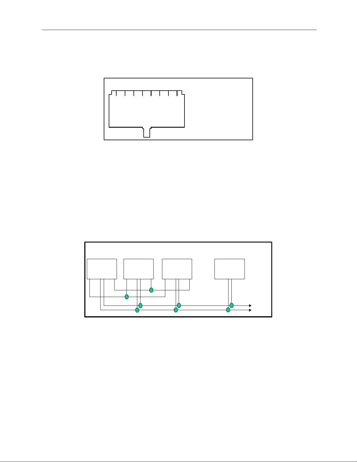
4.2.1 Crossmute
When a parallel console operator keys a microphone in the same room, the crossmute function mutes the receive
audio path of the other parallel consoles. This prevents any unwanted audio loops that could occur, causing a loud
squeal on the paralleled speakers.
Console 1: Console 2: Console 3:
Offsite
Console 4:
Line 1
1 2 3 4 5 6 7 8 1 2 3 4 5 6 7 8 1 2 3 4 5 6 7 8 1 2 3 4 5 6 7 8
Line 1Line 1Line 1
Line -
Line +
Figure 5 Crossmute Function example.
Feedback may be avoided by muting the receive audio of the other consoles which are in parallel with a transmitting
console. This may be accomplished by connecting pins 1 and 8 of each of the consoles to be crossmuted as shown
in Figure 5. Pin 8 must be connected to provide a common ground. Figure 5 illustrates the connections between
consoles 1 through 3 that are in the same room and when one transmits, the receive audio on the other consoles will
be muted. Console 4 is off-site with no possibility of feedback, therefore, it is not connected and will not be muted.
Note: The intercom function will not work between crossmuted consoles.
Remote Control Console 7
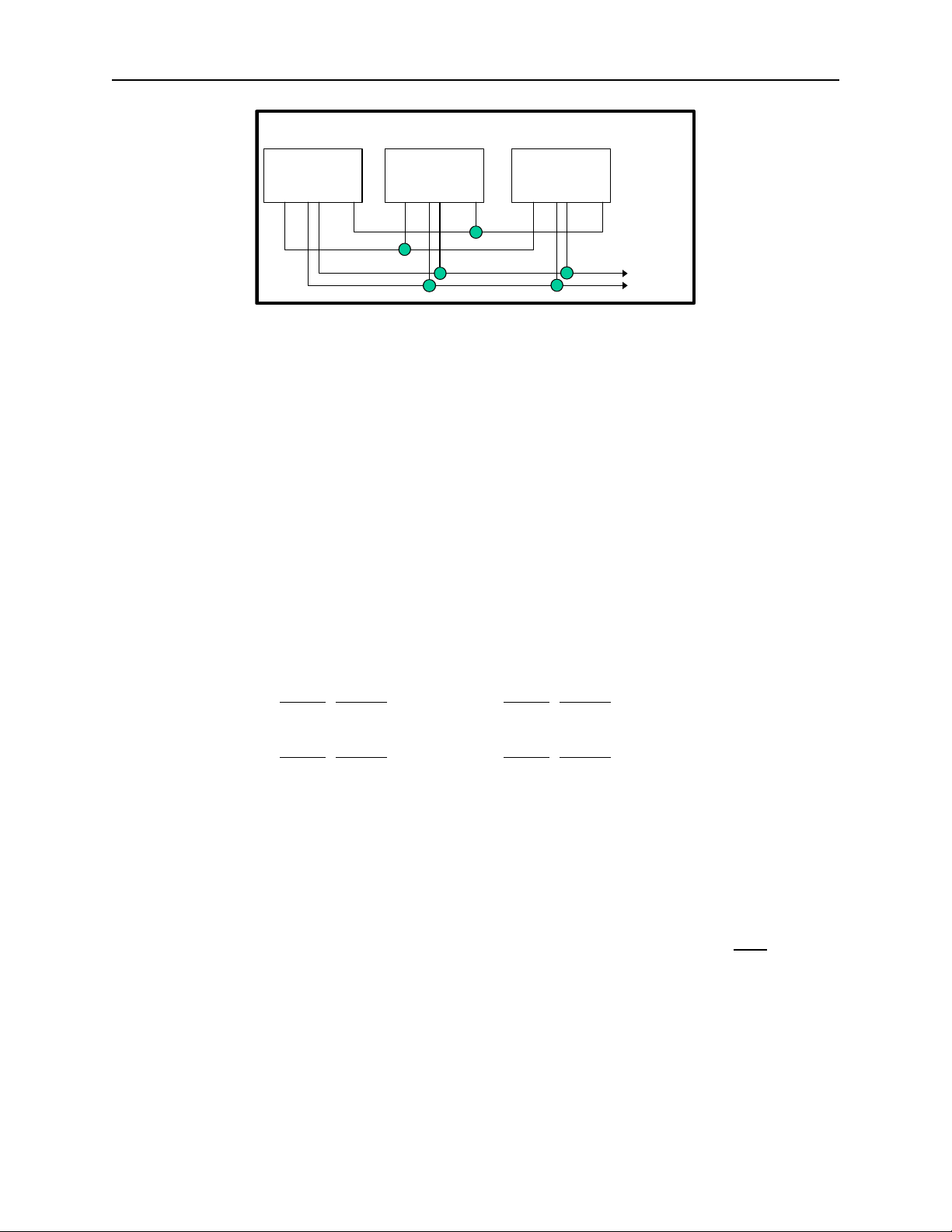
4.2.2 Supervisor Function
Console 1: Console 2: Console 3:
Line 1
1 2 3 4 5 6 7 8 1 2 3 4 5 6 7 8 1 2 3 4 5 6 7 8
Line 1Line 1
Line Line +
Figure 6 Supervisor Function Example.
The Supervisor Function enables a console, such as the C-2002, which has the capability to drive this line, to
disable all units on a particular line. This includes both PTT and RX audio. Its connection is similar to that of the
crossmute function. By wiring alone, it is possible to setup only specific consoles with this feature. Figure 6 shows
the connection scheme required to utilize this function. Pin 2 of all consoles are connected together. In addition,
Pin 8 is also connected together on all consoles, serving as a common ground for all consoles. Assuming that
console 1 has supervisory capability, when activated, Line 1 on parallel consoles 2 and 3 would then be inhibited
from both Transmit and Receive.
4.2.3 Relay Contact Closure For Local Control
The relay is normally open and provides a dry contact closure during PTT functions between pins 7 and 8 of the line
jack. The relay closure can carry 500mA at 12VDC or 250mA at 115VAC. When using the intercom function the
relay is not activated. If this relay closure is used for local control (or any other case where tone bursts are not used
for signaling) disabling the tone generation is recommended by entering the setup mode.
4.2.4 Two-Wire/Four-Wire Mode
The C-2002 comes standard with a jumper selectable two or four-wire option. Note: The C-2002 is shipped in the
four-wire mode. Two-wire mode is accomplished by the following jumper positions:
Two-Wire: Jumper
Line 1 JP18 A Line 2 JP22 A
Line 1 JP19 A Line 2 JP23 A
Four-Wire: Jumper
Line 1 JP18 B Line 2 JP22 B
Line 1 JP19 B Line 2 JP23 B
The RX pair is now on pins 3 and 6 on the connector and the TX pair is on pins 4 and 5. Once the transmit and
receive paths are separated the impedance of each side must be set.
Position Jumper Position
Position Jumper Position
4.2.5 RX Side Settings
In 4 Wire mode, the RX side is jumper selectable for a 600 ohm impedance or 10k ohm impedance. If only one
console is on the line (no parallel consoles) then place J17 (Line 1) or J25 (Line 2) in the A position for a 600 Ohm
line impedance. If more than one console is on one line, then place J17 (Line 1) or J25 (Line 2) on ONE
the A position and all other consoles in the B position. Each console added to the system will result in line loss.
The following chart gives an indication as to how much loss can be expected. The first console in the system is set
for an impedance of 600 ohms out (approximately). Each console added to the system thereafter is set for an
impedance of 10k ohms. As the chart indicates on the following page , the more consoles bridged on the line, the
lower the line impedance and the greater the loss in audio level. In 2 Wire mode, all consoles should have J17
(Line 1) or J25 (Line 2) in the “B” position.
console in
8 Vega’s C-2002
Console # J8 Position Impedance Impedance Loss (dB)
1 A 604 604 0.0
2 B 10k 569 -0.5
3 B 10k 539 -1.0
4 B 10k 511 -1.5
5 B 10k 486 -1.9
6 B 10k 464 -2.3
Level adjustment can be made to the receive audio by entering the setup mode or adjusting the RX level POT inside
the C-2002.
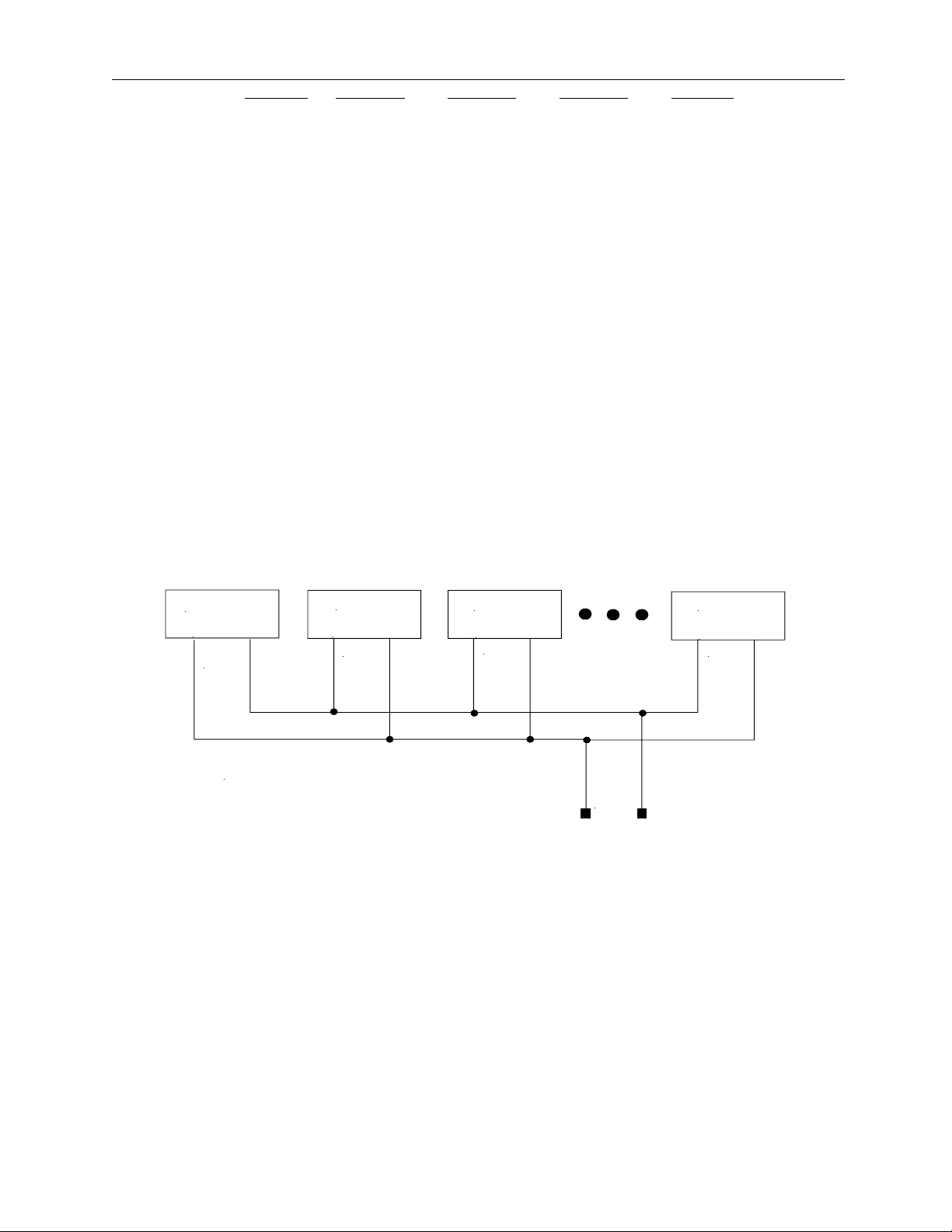
4.2.6 TX Side Settings
The C-2002 TX output circuitry has a DPDT relay that is used to connect and disconnect the TX output transformer
from the TX line based on PTT status. This allows a very large number of consoles to be attached to the line in
parallel, because only the transmitting unit will be directly connected to the line. When not transmitting, the DPDT
relay is connected to 600 ohms or open circuit depending on the number of console connected in parallel to the line.
If only one console is attached, this unit should have J16 (Line 1) or J26 (Line 2) in the “A” position. This makes it
the effective master and terminates the line with 600 ohms. If there are more than one console connected in parallel,
one console should be designated as the master by placing J16 (Line 1) or J26 (Line 2) in the “A” position and the
remaining consoles should be designated as a slave and should have J16 (Line 1) or J26 (Line 2) placed in the “B”
position. In this manner, the impedance looking back into the parallel configuration of consoles is still 600 ohms.
Figure 7 shows the basic configuration. The C-2002 could also be the master in this configuration. NOTE: If any of
the consoles connected in parallel are not C-2002’s, then all the C-2002’s should be configured as slaves.
Additionally, J2 (Line 1) or J4 (Line 2) should be used as a TX line impedance correction if there are consoles other
than the C-2002 connected in parallel. J2 (Line 1) or J4 (Line 2) position “B” adds another 600ohms to the output
TX line. J2 (Line 1) or J4 (Line 2) Position “A” is straight through.
Master
J12 POS A
600
ohms
Slave
J12 POS B
open
Slave
J12 POS B
open
Slave
J12 POS B
open
C2000 Multiple Console Configuration
Leased
Line
Figure 7 Master/Slave Console Configuration.
4.2.7 Transmit Monitor
In a four-wire system with parallel consoles, the transmit line may be monitored. Refer to section 4.3.2, the monitor
level setup on adjusting the level. The transmit monitor is not needed in two-wire mode as the transmit audio is
already on the receive circuit. The transmit monitor, in 4 wire mode, is used to detect transmit activity for the TX
Detect LED.

Remote Control Console 9
4.3 Level Adjustments
4.3.1 Transmit Side Adjustments
The transmit audio consists of multiple audio sources – microphone audio, AUX input, function tones, and DTMF
tones. Each audio sources is summed or generated in the DSP with the analog signal being generated on a single
DAC. The following is a list of the potentiometers that affect the transmit path.
Reference
R125 Line 1 TX Output Level Adjustment
R123 Line 1 TX Monitor Level Adjustment
R143 Line 2 TX Output Level Adjustment
R162 Line 2 TX Monitor Level Adjustment
R196 Desk Microphone Adjustment
MIC INPUT LEVEL ADJUST:
Care should be taken to avoid overdriving the input TX circuitry, as this will distort the audio. Make sure you have
enabled the desired Microphone connection in setup mode. Saying and holding the word “Four” is a good audio
level test vocalization. Use a strong tone of voice.
When adjusting the Desk Microphone audio input level, make sure that the Desk Microphone is at the normal
distance from the operator when setting the level. Connect a oscilloscope to Test point TP13 and adjust R196 to
approximately 3.5Vp-p.
TX OUTPUT LEVEL ADJUST:
The transmit level potentiometer is used to adjust the output level of the transmit audio so that it is calibrated with
the tone levels that were set in setup mode. Calibration of the TX line will vary depending on system variables as
well as the number of consoles found in parallel on the line. A easy way to align the console for the correct level is
to press and hold the PTT key. While the console is keyed up, the unit will, by default, generate a Hold tone at
–20dBm. A meter reading dbm can then be used and R125 (Line 1) or R143 (Line 2) adjusted to read the correct
value.
Description
4.3.2 Transmit Monitor Setup
The transmit monitor provides a portion of the transmit audio of a four-wire circuit to the receive path. This allows
the console operator to listen to the transmissions of parallel console operators. To set this level have a parallel
console operator press the intercom button. Adjust R123 (Line 1) or R162 (Line 2) until the level is comfortable in
the handset/headset earpiece or the speaker. Make sure this feature is enabled or no audio will be passed.
See Setup Mode.
4.3.3 RX Level Adjustment
The RX level should be adjusted so that the maximum level coming into the console use the entire range of the
ADC, which is 0-4V. A test tone of +3dBm to -5dBm coming into the line interface is a good value to use. Adjust
R153 (Line 1) so that the signal seen on an oscilloscope at Test point TP11 is approximately 3.5Vp-p or R161
(Line2) so that the signal seen on an oscilloscope at Test point TP12 is approximately 3.5Vp-p

10 Vega’s C-2002
5 Hardware Overview
The C-2002 is a Two-line, multi-mode console designed specifically for small to medium level system
requirements. All functions are housed in a single small modern looking console.
5.1 C-2002 Console
The C-2002 consists of the following sub-assemblies enclosed in the single case: Main Processing Board, Keypad
PCB and Display.
5.1.1 Main PCB
The Main PCB is mounted to the bottom of the enclosure using 4 #6 screws. It contains the DSP that handles all
audio processing and user interface features. Two stereo Digital to Analog Converter (DAC) is utilized to generate
audio for transmission, handset sidetone, and receive audio. Two stereo Analog to Digital Converter (ADC) on the
main board digitizes audio from the line, microphones and the auxiliary interface. All audio detection, generation,
and filtering are performed within the DSP. Seven potentiometers are available for I/O signal level adjustment, in
addition to the software level control.
5.1.1.1 Line Interface
The Line Interface is an 8 pin RJ-45 connector, using either the standard tone control format compatible with
Motorola and M/A ComNet Ericsson/GE or Local Control relay closure. The line interface may be hardware
configured for either two-wire or four-wire operation and may be factory modified to accommodate non-industry
standard tone control formats if desired. This is usually a software only change.
5.1.2 Keypad PCB
The Keypad board is interfaced to the main board via a 40-pin ribbon cable. The Keypad board contains the LED’s,
the entire key map matrix and the panel microphone. The driver circuitry for each component is located on the Main
PCB.
5.1.3 Display
A Vacuum Florescent LCD display provides channel/numeric indication, clock and audio-level meter. The display
is mounted to the front panel and is connected via a 14-pin IDC cable assembly.

Remote Control Console 11
6 Theory of Operation
The C-2002 is a Digital Signal Processor (DSP) based product. Because of this, many of the signals that once could
be probed on older products, are handled within the DSP itself. This would include DTMF generators and
decoders, notch filters, tone generators and decoders, and all of the audio summing. A great deal of the gain
controls are included within the software of the DSP. There are four analog audio sections on the C-2002, they are:
RX Input: Audio received on the line from an external source.
RX Output: RX Input audio that has been sampled and processed by the DSP, then sent to a local speaker.
TX Input: Audio from a local microphone, handset or auxiliary audio source.
TX Output: TX Input audio that has been sampled and processed by the DSP, or internally generated
Tones/DTMF that is summed with TX Input audio. The result is routed to TX line out.
The following sections discuss the portions of the C-2002 that can be tested using a common oscilloscope and
voltage meter by a qualified service technician.
6.1 Microphone Input Paths
Audio can be input from four locations. These are the desk microphone jack (J24, RJ-11 modular), handset jack
(J21, RJ-12 modular), panel mic (built into keypad PCB), and the auxiliary connector (J36) on the rear of the unit.
For each of these inputs, a single inverting Op-Amp gain stage exists to bring the maximum expected level of the
audio up to approximately 3.8Vp-p. This is the optimum level for the analog to digital converters (ADC). The trim
potentiometer R196 set the audio levels from the desk microphone jack, there is no Handset microphone gain
adjustment. All audio inputs, mentioned previously, share one half of the ADC (U12) with a CMOS switch (U34-B)
used to route audio from the appropriate source to the actual input pin of the ADC. The auxiliary input (J36-4) is
used to include an additional audio source into the transmit path. It has an integrated PTT (J36-2) input that when
pulled low will select audio from this source for transmission. Audio or tone levels injected at the Auxiliary input
should be on the order of 1.5 Vp-p, as the fixed gain ratio of R190/R189 = 2 and the target ADC level is
approximately 3.5vp-p. There are no hardware adjustments available for the Panel microphone.
6.2 Audio Output Paths
SPEAKER AUDIO:
Speaker audio originates, as all audio output signals do, from the DSP. The digitized audio is clocked to DAC U10,
pin 1. The analog audio is sourced on U10 pin 8, passes through an analog filter and inverting gain stage U14-A,
before arriving at the speaker audio driver U24. The two Watt speaker driver audio is passed to the speaker
connector J5. Speaker audio levels are software controlled.
TRANSMIT AUDIO LINE (ONE/TWO):
Transmit audio, still digitized, is clocked to U9 pin 1 for both transmit channels. Analog transmit audio can be seen
on U9 pins (8/5). Transmit audio passes through an analog filter before reaching the output gain stage. TX output
levels can be adjusted for lines (1/2) by potentiometers (R125/R143). Each Transit audio path is 600 Ohm
transformer coupled (T1/T4) and engaged during PTT by a relay contact closure (K4/K6). Transmit audio can be
found on connectors (J11/J27) pins 4(TX+) and 5(TX-).
HANDSET SIDETONE:
Handset sidetone is taken from U10 pin 5 and filtered. The output goes to an inverting op-amp stage and is coupled
through a 0.1uF cap and 150 ohm resistor. The sidetone level can be measured at TP10.
For complete schematic details, refer to Section 10 the Specifications section.
6.3 Line Receive Paths Line (One/Two)
Receive audio input can be found on the Line input connectors (J11/J27) pins 3(RX+) and 6(RX-). The receive
audio will pass through lightning protection and filtering before reaching a 10K transformer (T2/T3). The receive
audio path can be loaded to 600 Ohms by placing jumper (J17/J25) in the “A” position. Following the transformer
stage is a gain stage. Potentiometers (R153/R161) can be used to set receive audio levels at the ADC. This level can
be measured at test points (TP11/TP12). Finally, receive audio is sampled at U13 (pin 8/pin5).

12 Vega’s C-2002
6.4 System Clock Generation
The system clock is derived from a single 32.7680MHz Crystal Oscillator (Y1). The ADSP2189 DSP (U1)
processor uses this clock to generate a 65.536MHz internal instruction clock rate. The system clock is routed to the
Altera EPM7032AE44 PLD (U5) and divided into the signals necessary for audio processing. These signals include
the MCLK (2.048MHz), SCLK (512kHz), LRCLK (8kHz) and FS (16kHz frame sync). Another signal generate by
the PLD is B0 (U5-28). This signal is used by DSP software to sync the bit frames at start up. B0 is the inverse of
LRCLK. U5-31 is a clock signal that is the inverse of SCLK. The DSP serial port requires this signal, usually called
the bit clock.
6.5 Non-Volatile Memory (EEPROM)
All the system configuration and parameter storage is maintained in the non-volatile memory of U3. The serial
EEPROM AT24C16, has 16kbits of memory. The DSP writes and reads to the EEPROM via two of its Flag Pins.
6.6 User I/O
The Keypad and Seven Segment display are the main components to the User I/O scheme. The DSP controls the I/O
with a series of register and latches (U22, U23, U26, U27, U28, U16). Chip Selects originate from the DSP, but are
modified to their usable state by the PLD. The Chip selects are R-CS0,1(read) and W-CS0,1,2,3(write). They are
generated by DSP signals RD, WR, IOMS and address lines A0,A1,A5.
6.7 Clone Mode Serial Port
The C-2002 can be used to copy the memory contents of one C-2002 to another. This is done with the serial data
port on the back of the unit (J3). The circuitry used is a simple level conversion scheme to take the 3.3Vdc serial
data stream from the DSP and convert it to a 10Vdc signal at the port. The port can only be used C-2002-to-C-2002.
A standard 16C550 UART U18 is included in the DSP’s memory map. The UART levels are converted to standard
RS-232C by U20. The C-2002 firmware code can be updated through this port from any Windows 9x or greater
PC. See the www.vega-signaling.com
website for software updates.
6.8 Power Regulation and Reset Control
Input power is a 12Vdc wall mount regulator. The input connector (J35) is a center positive, 2.5mm jack. It is
connected to protection circuitry consisting of a fuse and dual diodes used to protect the source if auxiliary power is
connected to J36. The system DC power requirements are 3.3V and 2.5V(U8) for the DSP and 5V(U6), 10V(U7)
for the analog circuitry.
 Loading...