


 Loading...
Operation Manual
Model T400
Photometric Ozone Analyzer
© TELEDYNE ADVANCED POLLUTION INSTRUMENTATION (TAPI)
9480 CARROLL PARK DRIVE
SAN DIEGO, CA 92121-5201
USA
Toll-free Phone: 800-324-5190
Phone: 858-657-9800
Fax: 858-657-9816
Email: api-sales@teledyne.com
Website: http://www.teledyne-api.com/
Copyright 2010-2012 |
06870C DCN6332 |
Teledyne Advanced Pollution Instrumentation |
13 January 2012 |
ABOUT TELEDYNE ADVANCED POLLUTION INSTRUMENTATION (TAPI)
Teledyne Advanced Pollution Instrumentation (TAPI), a business unit of Teledyne Instruments, Inc., is a worldwide market leader in the design and manufacture of precision analytical instrumentation used for air quality monitoring, continuous emissions monitoring, and specialty process monitoring applications. Founded in San Diego, California, in 1988, TAPI introduced a complete line of Air Quality Monitoring (AQM) instrumentation, which comply with the United States Environmental Protection Administration (EPA) and international requirements for the measurement of criteria pollutants, including CO, SO2, NOX and Ozone.
Since 1988 TAPI has combined state-of-the-art technology, proven measuring principles, stringent quality assurance systems and world class after-sales support to deliver the best products and customer satisfaction in the business.
For further information on our company, our complete range of products, and the applications that they serve, please visit www.teledyne-api.com or contact sales@teledyne-api.com.
NOTICE OF COPYRIGHT
© 2010-2012 Teledyne Advanced Pollution Instrumentation. All rights reserved.
TRADEMARKS
All trademarks, registered trademarks, brand names or product names appearing in this document are the property of their respective owners and are used herein for identification purposes only.
06870C DCN6332 |
i |

Teledyne API – Model T400 Photometric Ozone Analyzer
This page intentionally left blank.
ii |
06870C DCN6332 |
IMPORTANT SAFETY INFORMATION
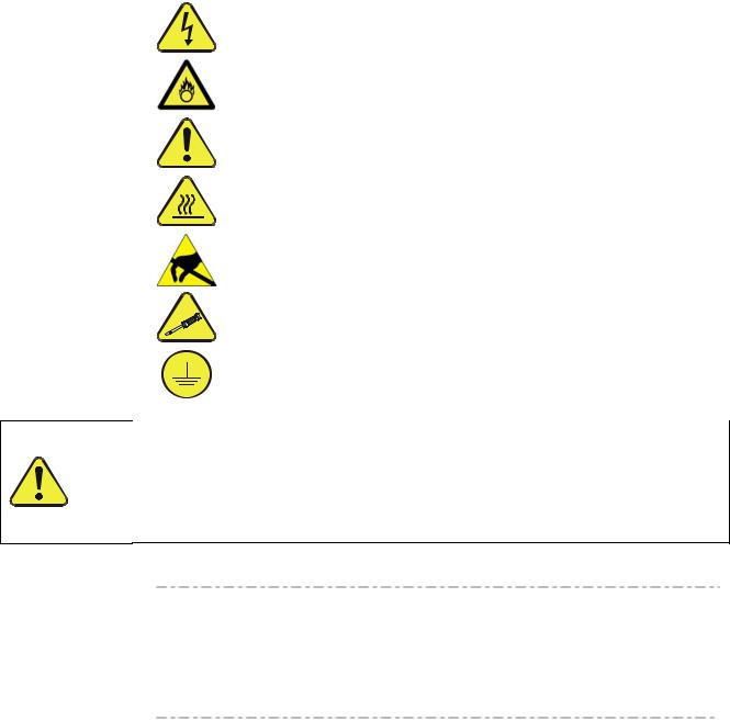
Important safety messages are provided throughout this manual for the purpose of avoiding personal injury or instrument damage. Please read these messages carefully. Each safety message is associated with a safety alert symbol, and are placed throughout this manual and inside the instrument. The symbols with messages are defined as follows:
WARNING: Electrical Shock Hazard
HAZARD: Strong oxidizer
GENERAL WARNING/CAUTION: Read the accompanying message for specific information.
CAUTION: Hot Surface Warning
Do Not Touch: Touching some parts of the instrument without protection or proper tools could result in damage to the part(s) and/or the instrument.
Technician Symbol: All operations marked with this symbol are to be performed by qualified maintenance personnel only.
Electrical Ground: This symbol inside the instrument marks the central safety grounding point for the instrument.
CAUTION
This instrument should only be used for the purpose and in the manner described in this manual. If you use this instrument in a manner other than that for which it was intended, unpredictable behavior could ensue with possible hazardous consequences.
NEVER use any gas analyzer to sample combustible gas(es).
Note |
Technical Assistance regarding the use and maintenance of the T100 or any |
|
other Teledyne API product can be obtained by contacting Teledyne API’s |
||
|
||
|
Customer Service Department: |
Phone: 800-324-5190
Email: api-customerservice@teledyne.com
or by accessing various service options on our website at 7http://www.teledyne-api.com/.
06870C DCN6332 |
iii |

Teledyne API – Model T400 Photometric Ozone Analyzer
CONSIGNES DE SÉCURITÉ
Des consignes de sécurité importantes sont fournies tout au long du présent manuel dans le but d’éviter des blessures corporelles ou d’endommager les instruments. Veuillez lire attentivement ces consignes. Chaque consigne de sécurité est représentée par un pictogramme d’alerte de sécurité; ces pictogrammes se retrouvent dans ce manuel et à l’intérieur des instruments. Les symboles correspondent aux consignes suivantes :
AVERTISSEMENT : Risque de choc électrique
DANGER : Oxydant puissant
AVERTISSEMENT GÉNÉRAL / MISE EN GARDE : Lire la consigne complémentaire pour des renseignements spécifiques
MISE EN GARDE : Surface chaude
Ne pas toucher : Toucher à certaines parties de l’instrument sans protection ou sans les outils appropriés pourrait entraîner des dommages aux pièces ou à l’instrument.
Pictogramme « technicien » : Toutes les opérations portant ce symbole doivent être effectuées uniquement par du personnel de maintenance qualifié.
Mise à la terre : Ce symbole à l’intérieur de l’instrument détermine le point central de la mise à la terre sécuritaire de l’instrument.
MISE EN GARDE
Cet instrument doit être utilisé aux fins décrites et de la manière décrite dans ce manuel. Si vous utilisez cet instrument d’une autre manière que celle pour laquelle il a été prévu, l’instrument pourrait se comporter de façon imprévisible et entraîner des conséquences dangereuses.
NE JAMAIS utiliser un analyseur de gaz pour échantillonner des gaz combustibles!
iv |
06870C DCN6332 |

WARRANTY
Teledyne Advanced Pollution Instrumentation, a business unit of Teledyne Instruments, Inc., herein referred to as TAPI, warrants its products as follows:
WARRANTY POLICY (02024D)
Prior to shipment, TAPI equipment is thoroughly inspected and tested. Should equipment failure occur, TAPI assures its customers that prompt service and support will be available.
COVERAGE
After the warranty period and throughout the equipment lifetime, TAPI stands ready to provide on-site or in-plant service at reasonable rates similar to those of other manufacturers in the industry. All maintenance and the first level of field troubleshooting is to be performed by the customer.
NON-API MANUFACTURED EQUIPMENT
Equipment provided but not manufactured by TAPI is warranted and will be repaired to the extent and according to the current terms and conditions of the respective equipment manufacturers warranty.
GENERAL
During the warranty period, TAPI warrants each Product manufactured by TAPI to be free from defects in material and workmanship under normal use and service. Expendable parts are excluded.
If a Product fails to conform to its specifications within the warranty period, TAPI shall correct such defect by, at TAPI's discretion, repairing or replacing such defective Product or refunding the purchase price of such Product.
The warranties set forth in this section shall be of no force or effect with respect to any Product:
(i) that has been altered or subjected to misuse, negligence or accident, or (ii) that has been used in any manner other than in accordance with the instruction provided by TAPI, or (iii) not properly maintained.
THE WARRANTIES SET FORTH IN THIS SECTION AND THE REMEDIES THEREFORE ARE EXCLUSIVE AND IN LIEU OF ANY IMPLIED WARRANTIES OF MERCHANTABILITY, FITNESS FOR PARTICULAR PURPOSE OR OTHER WARRANTY OF QUALITY, WHETHER EXPRESSED OR IMPLIED. THE REMEDIES SET FORTH IN THIS SECTION ARE THE EXCLUSIVE REMEDIES FOR BREACH OF ANY WARRANTY CONTAINED HEREIN. TAPI SHALL NOT BE LIABLE FOR ANY INCIDENTAL OR CONSEQUENTIAL DAMAGES ARISING OUT OF OR RELATED TO THIS AGREEMENT OF TAPI'S PERFORMANCE HEREUNDER, WHETHER FOR BREACH OF WARRANTY OR OTHERWISE.
TERMS AND CONDITIONS
All units or components returned to TAPI should be properly packed for handling and returned freight prepaid to the nearest designated Service Center. After the repair, the equipment will be returned, freight prepaid.
ATTENTION |
AVOID WARRANTY INVALIDATION |
|
Failure to comply with proper anti-Electro-Static Discharge (ESD) |
|
handling and packing instructions and Return Merchandise Authorization |
|
(RMA) procedures when returning parts for repair or calibration may void |
|
your warranty. For anti-ESD handling and packing instructions please |
|
refer to “Packing Components for Return to Teledyne API’s Customer |
|
Service” in the Primer on Electro-Static Discharge section of this manual, |
|
and for RMA procedures please refer to our Website at http://www.teledyne- |
|
api.com under Customer Support > Return Authorization. |
|
|
06870C DCN6332 |
v |

Teledyne API – Model T400 Photometric Ozone Analyzer
This page intentionally left blank.
vi |
06870C DCN6332 |
ABOUT THIS MANUAL
Presented here is information regarding the documents that are included with this manual (Structure) and how the content is organized (Organization).
STRUCTURE
This T400 manual, PN 06870 is comprised of multiple documents, assembled in PDF format, as listed below.
Part No. |
Rev |
Name/Description |
06870 |
B |
Operation Manual, T400 Photometric Ozone Analyzer |
04402 |
E |
Appendix A, Menu Trees and related software documentation |
06851 |
A |
Spare Parts List (in Appendix B of this manual) |
|
|
|
006190200 |
B |
AKIT, Expendables |
07558 |
A |
Recommended Spares Stocking Levels |
04473 |
A |
IZS Expendables |
|
|
|
04404 |
C |
Appendix C, Repair Form |
06913 |
A |
Interconnect Diagram, T400 (in Appendix D of this manual) |
069130100 |
A |
Interconnect Table, T400 (in Appendix D of this manual) |
|
|
|
|
|
Schematics (in Appendix D of this manual): |
04524 |
E |
PCA, 04522, Relay Board |
03632 |
A |
PCA, 03631, 0-20mA Driver |
|
|
|
04354 |
D |
PCA, 04003, Pressure/Flow Transducer Interface |
04420 |
B |
PCA, 04120, UV Detector Preamp |
04421 |
A |
PCA, 04166, UV Lamp Power Supply |
|
|
|
04422 |
A |
PCA, 04144, DC Heater/Thermistor |
05803 |
B |
SCH, PCA 05802, MOTHERBOARD, GEN-5 |
06698 |
D |
SCH, PCA 06670, INTRFC, LCD TCH SCRN, |
|
|
|
06882 |
B |
SCH, LVDS TRANSMITTER BOARD |
06731 |
B |
SCH, AUX-I/O BOARD |
Note |
We recommend that this manual be read in its entirety before any attempt |
|
is made to operate the instrument. |
|
|
06870C DCN6332 |
vii |

Teledyne API – Model T400 Photometric Ozone Analyzer
ATTENTION
IMPORTANT
ORGANIZATION
This manual is divided among three main parts and a collection of appendices at the end.
Part I contains introductory information that includes an overview of the calibrator, descriptions of the available options, specifications, installation and connection instructions, and the initial calibration and functional checks. Part I ends with a Frequently Asked Questions (FAQs) section and a Glossary section.
Part II comprises the operating instructions, which include basic, advanced and remote operation, calibration, diagnostics, testing, validating and verifying.
Part III provides detailed technical information, such as theory of operation, maintenance, and troubleshooting and repair. It also contains a section that provides important information about electro-static discharge and avoiding its consequences.
The appendices at the end of this manual provide support information such as, versionspecific software documentation, lists of spare parts and schematics.
CONVENTIONS USED
In addition to the safety symbols as presented in the Important Safety Information page, this manual provides special notices related to the safety and effective use of the analyzer and other pertinent information.
Special Notices appear as follows:
COULD DAMAGE INSTRUMENT AND VOID WARRANTY
This special notice provides information to avoid damage to your instrument and possibly invalidate the warranty.
IMPACT ON READINGS OR DATA
Could either affect accuracy of instrument readings or cause loss of data.
Note |
Pertinent information associated with the proper care, operation or |
|
maintenance of the analyzer or its parts. |
viii |
06870C DCN6332 |
REVISION HISTORY
This section provides information regarding the release of and changes to this T400 Operation Manual, PN 06870.
Document |
PN |
Rev |
DCN |
Change Summary |
2012 January 13, Rev C |
|
|
|
|
T400 Op Manual |
06870 |
C |
6332 |
Technical Updates: |
|
|
|
|
Figure 3-9, add connection line for =5V to external device. |
|
|
|
|
In Electrical Connections section, add Concentration Relay |
|
|
|
|
Alarm option (Section 3.3.1.7). |
|
|
|
|
Section 3.3.1.8, modify Multidrop connection section to |
|
|
|
|
clarify instructions and add detail. |
|
|
|
|
Correct COM1 default baud rate value to 115,200 (was: |
|
|
|
|
19,200) per DCR 7062. |
|
|
|
|
Administrative Updates, i.e., reorganized structure and |
|
|
|
|
renamed sections: |
|
|
|
|
Converted Options section to tabular format and moved to |
|
|
|
|
Section 1 as Table 1-1. |
|
|
|
|
Moved FAQ’s from Section 4 to end of Troubleshooting |
|
|
|
|
section. |
|
|
|
|
Moved Glossary from Section 4 to end of manual after ESD |
|
|
|
|
section, before Appendices. |
|
|
|
|
Grouped communications setup and operation into one |
|
|
|
|
section (Section 6). |
|
|
|
|
Renamed Part III from “Technical Information” to |
|
|
|
|
“Maintenance and Service”. |
|
|
|
|
Renamed “Troubleshooting and Repair” to “Troubleshooting |
|
|
|
|
and Service”. |
|
|
|
|
Renamed section “Theory of Operation” to “Principles of |
|
|
|
|
Operation” and moved after “Troubleshooting and Service” |
|
|
|
|
section. |
|
|
|
|
In Appendix B replaced M400E RSSL with T400 RSSL |
|
|
|
|
Reassembled Appendix D with updated 04524 Relay Card |
|
|
|
|
Schem from Rev D to Rev E and 06731 Aux I/O Schem from |
|
|
|
|
Rev A to Rev B. |
|
|
|
|
|
06870C DCN6332 |
ix |

|
|
|
|
|
Teledyne API – Model T400 Photometric Ozone Analyzer |
|
|
|
|
|
|
|
|
|
Document |
PN |
Rev |
DCN |
Change Summary |
|
|
2011 April 15, Rev B |
|
|
|
|
|
|
T400 Op Manual |
06870 |
B |
6049 |
Add North American certifications |
|
|
|
|
|
|
Add MODBUS Setup instructions to Remote Op section |
|
|
|
|
|
|
Replace interconnects with correct documents (in Appendix D) |
|
|
|
|
|
|
Add UV Safety message (in startup, mntnc, & repairs sections) |
|
|
|
|
|
|
Clarify PASSWORD enable/disable description, Section 6.4.2. |
|
|
|
|
|
|
|
|
2010 September 07, T400 Operation Manual, PN06870 Rev A, DCN5836, Initial Release
x |
06870C DCN6332 |

This page intentionally left blank.
06870C DCN6332 |
xi |
06870C DCN6332

TABLE OF CONTENTS |
|
1. INTRODUCTION, FEATURES AND OPTIONS ................................................................. |
25 |
1.1. Overview ....................................................................................................................................................... |
25 |
1.2. Features ........................................................................................................................................................ |
25 |
1.3. Options .......................................................................................................................................................... |
26 |
2. SPECIFICATIONS, APPROVALS & COMPLIANCE ......................................................... |
29 |
2.1. Specifications ................................................................................................................................................ |
29 |
2.2. EPA Equivalency Designation....................................................................................................................... |
31 |
2.3. Approvals and Certifications ......................................................................................................................... |
32 |
2.3.1. Safety..................................................................................................................................................... |
32 |
2.3.2. EMC ....................................................................................................................................................... |
32 |
2.3.3. Other Type Certifications ....................................................................................................................... |
32 |
3. GETTING STARTED .......................................................................................................... |
33 |
3.1. Unpacking the T400 Analyzer ....................................................................................................................... |
33 |
3.1.1.1. Ventilation Clearance ..................................................................................................................... |
34 |
3.2. Instrument layout........................................................................................................................................... |
35 |
3.2.1. Front Panel ............................................................................................................................................ |
35 |
3.2.2. Rear Panel ............................................................................................................................................. |
39 |
3.2.3. Internal Chassis Layout ......................................................................................................................... |
41 |
3.3. Connections and Setup................................................................................................................................. |
42 |
3.3.1. Electrical Connections ........................................................................................................................... |
42 |
3.3.1.1. Connecting Power .......................................................................................................................... |
42 |
3.3.1.2. Connecting Analog Inputs (Option) ................................................................................................ |
43 |
3.3.1.3. Connecting Analog Outputs ........................................................................................................... |
43 |
3.3.1.4. Current Loop Analog Outputs (Option 41) Setup ........................................................................... |
44 |
3.3.1.5. Connecting the Status Outputs ...................................................................................................... |
46 |
3.3.1.6. Connecting the Control Inputs........................................................................................................ |
47 |
3.3.1.7. Connecting the Concentration Alarm Relay (Option 61)................................................................ |
48 |
3.3.1.8. Connecting the Communications Interfaces .................................................................................. |
50 |
3.3.2. Pnenumatic Connections....................................................................................................................... |
56 |
3.3.2.1. About Zero Air and Calibration Gas ............................................................................................... |
56 |
3.3.2.2. Pneumatic Setup for Basic Configuration....................................................................................... |
59 |
3.3.2.3. Pneumatic Setup for the T400 Analyzer with Internal Zero/Span Option (IZS) ............................. |
60 |
3.3.3. Pneumatic Setups for Ambient Air Monitoring....................................................................................... |
61 |
3.3.3.1. Pneumatic Set Up for T400’s Located in the Same Room Being Monitored ................................. |
61 |
3.3.3.2. Pneumatic Set Up for T400’s Monitoring Remote Locations ......................................................... |
62 |
3.4. Startup, Functional Checks, and Initial Calibration ....................................................................................... |
63 |
3.4.1. Start Up.................................................................................................................................................. |
63 |
3.4.2. Warning Messages ................................................................................................................................ |
63 |
3.4.3. Functional Check ................................................................................................................................... |
65 |
3.4.4. Initial Calibration .................................................................................................................................... |
65 |
3.4.4.1. Interferents for O3 Measurement.................................................................................................... |
65 |
3.4.5. Initial Calibration Procedure for T400 Analyzers without Options ......................................................... |
66 |
3.4.5.1. Verifying the T400 Reporting Range Settings................................................................................ |
66 |
3.4.5.2. Verify the Expected O3 Span Gas Concentration:.......................................................................... |
67 |
3.4.5.3. Initial Zero/Span Calibration Procedure: ........................................................................................ |
69 |
3.5. Configuring the Internal Zero/Span Option (IZS) .......................................................................................... |
70 |
3.5.1. Verify the O3 Generator and Expected O3 Span Concentration Settings.............................................. |
70 |
3.5.2. Setting the O3 Generator Low-Span (Mid Point) Output Level .............................................................. |
71 |
3.5.3. Turning on the Reference Detector Option............................................................................................ |
72 |
3.5.4. Initial Calibration and Conditioning of T400 Analyzers with the IZS Option Installed............................ |
73 |
3.5.4.1. Initial O3 Scrubber Conditioning ..................................................................................................... |
73 |
3.5.4.2. Verifying the T400 Reporting Range Settings................................................................................ |
74 |
06870C DCN6332 |
xiii |

Table of Contents |
Teledyne API – Model T400 Photometric Ozone Analyzer |
|
3.5.4.3. Initial Zero/Span Calibration Procedure: ........................................................................................ |
74 |
|
3.6. Calibration Valve Options.............................................................................................................................. |
|
74 |
3.6.1. Ambient Zero/Ambient Span Valves (Opt 50A) ..................................................................................... |
74 |
|
3.6.1.1. Pneumatic Setup for the T400 Analyzer with Zero/Span Valve Option ......................................... |
76 |
|
3.6.2. Internal Zero Span (IZS) Option (OPT 50G).......................................................................................... |
78 |
|
4. OVERVIEW OF OPERATING MODES .............................................................................. |
|
83 |
4.1. Sample Mode ................................................................................................................................................ |
|
85 |
4.1.1. Test Functions ....................................................................................................................................... |
|
86 |
4.1.2. Warning Messages ................................................................................................................................ |
|
88 |
4.2. Calibration Mode ........................................................................................................................................... |
|
89 |
4.3. SETUP Mode ................................................................................................................................................ |
|
90 |
4.3.1. Password Security ................................................................................................................................. |
|
90 |
4.3.2. Primary Setup Menu .............................................................................................................................. |
|
90 |
5. SETUP MENU .................................................................................................................... |
|
93 |
5.1. SETUP CFG: Configuration Information................................................................................................... |
|
93 |
5.2. SETUP DAS: Internal Data acquisition System ....................................................................................... |
94 |
|
5.3. SETUP ACAL: Automatic Calibration Option ........................................................................................... |
94 |
|
5.4. SETUP RNGE: Analog Output Reporting Range Configuration .............................................................. |
94 |
|
5.4.1.1. Physical Range versus Analog Output Reporting Ranges............................................................. |
94 |
|
5.4.1.2. Analog Output Ranges for O3 Concentration ................................................................................. |
95 |
|
5.4.1.3. RNGE MODE SNGL: Single Range Mode Configuration ..................................................... |
97 |
|
5.4.1.4. RNGE MODE DUAL: Dual Range Mode Configuration....................................................... |
98 |
|
5.4.1.5. RNGE MODE AUTO: Auto Range Mode Configuration ....................................................... |
99 |
|
5.4.1.6. SETUP RNGE UNIT: Setting the Reporting Range Unit Type .......................................... |
100 |
|
5.5. SETUP PASS: Password Protection..................................................................................................... |
|
101 |
5.6. SETUP CLK: Setting the T400 Analyzer’s Internal Time-of-Day Clock and Adjusting Speed.............. |
104 |
|
5.6.1.1. Setting the Internal Clock’s Time and Day .................................................................................. |
104 |
|
5.6.1.2. Adjusting the Internal Clock’s Speed........................................................................................... |
105 |
|
5.7. SETUP COMM: Communications Ports................................................................................................ |
|
106 |
5.7.1. ID (Machine Identification) .................................................................................................................. |
|
106 |
5.7.2. INET (Ethernet)................................................................................................................................... |
|
106 |
5.7.3. COM1 and COM 2 (Mode, Baud Rate and Test Port)........................................................................ |
106 |
|
5.8. SETUP VARS: Variables Setup and Definition ..................................................................................... |
107 |
|
5.9. SETUP DIAG :Diagnostics Functions.................................................................................................... |
|
109 |
5.10. Using the Model T400 Analyzer’s Analog I/O .......................................................................................... |
111 |
|
5.10.1. Adjusting & Calibrating the Analog Output Signals .......................................................................... |
112 |
|
5.10.1.1. Calibration of the Analog Outputs ............................................................................................. |
|
112 |
5.10.1.2. Enabling or Disabling the AutoCal for an Individual Analog Output.......................................... |
113 |
|
5.10.1.3. Automatic Group Calibration of the Analog Outputs ................................................................. |
114 |
|
5.10.1.4. Manual Calibration of the Analog Outputs Configured for Voltage Ranges.............................. |
116 |
|
5.10.1.5. Manual Adjustment of Current Loop Output Span and Offset .................................................. |
118 |
|
5.10.1.6. Analog Output Voltage / Current Range Selection.................................................................... |
121 |
|
5.10.1.7. Turning an Analog Output Over-Range Feature ON/OFF ........................................................ |
122 |
|
5.10.1.8. Adding a Recorder Offset to an Analog Output......................................................................... |
123 |
|
5.10.1.9. Selecting a Test Channel Function for Output A4..................................................................... |
124 |
|
5.10.2. AIN Calibration.................................................................................................................................. |
|
126 |
5.10.3. Configuring Analog Inputs (Option) .................................................................................................. |
|
127 |
6. COMMUNICATIONS SETUP AND OPERATION ............................................................ |
129 |
|
6.1. Data Terminal/Communication Equipment (DTE DCE)............................................................................. |
129 |
|
6.2. Communication Modes, Baud Rate and Port Testing................................................................................ |
129 |
|
6.2.1. Communication Modes ....................................................................................................................... |
|
130 |
6.2.2. COM Port Baud Rate.......................................................................................................................... |
|
132 |
6.2.3. COM Port Testing ............................................................................................................................... |
|
133 |
6.3. RS-232 ....................................................................................................................................................... |
|
134 |
6.4. RS-485 (Option) ......................................................................................................................................... |
|
134 |
6.5. Ethernet...................................................................................................................................................... |
|
134 |
6.5.1. Configuring Ethernet Communication Manually (Static IP Address) .................................................. |
135 |
|
6.5.2. Configuring Ethernet Communication with Dynamic Host Configuration Protocol (DHCP) ............... |
138 |
|
xiv |
06870C DCN6332 |
|

Teledyne API – Model T400 Photometric Ozone Analyzer |
Table of Contents |
|
6.5.3. Changing the Analyzer’s HOSTNAME ............................................................................................... |
|
141 |
6.6. USB Port .................................................................................................................................................... |
|
142 |
6.7. Communications Protocols ........................................................................................................................ |
|
142 |
6.7.1. MODBUS ............................................................................................................................................ |
|
142 |
6.7.2. Hessen................................................................................................................................................ |
|
144 |
6.7.3. Hessen COMM Port Configuration ..................................................................................................... |
|
145 |
6.7.4. Activating Hessen Protocol................................................................................................................. |
|
146 |
6.7.5. Selecting a Hessen Protocol Type...................................................................................................... |
|
147 |
6.7.6. Setting The Hessen Protocol Response Mode................................................................................... |
|
148 |
6.7.7. Hessen Protocol Gas List Entries ....................................................................................................... |
|
149 |
6.7.7.1. Gas List Entry Format and Definitions......................................................................................... |
|
149 |
6.7.7.2. Editing or Adding HESSEN Gas List Entries............................................................................... |
|
150 |
6.7.7.3. Deleting HESSEN Gas List Entries ............................................................................................. |
|
151 |
6.7.8. Setting Hessen Protocol Status Flags ................................................................................................ |
|
152 |
6.7.9. Instrument ID ...................................................................................................................................... |
|
153 |
7. DATA ACQUISITION SYSTEM (DAS) AND APICOM....................................................... |
|
155 |
7.1. DAS STATUS............................................................................................................................................. |
|
156 |
7.2. DAS Structure ............................................................................................................................................ |
|
156 |
7.3. DAS Channels............................................................................................................................................ |
|
157 |
7.3.1. DAS Default Channels........................................................................................................................ |
|
158 |
7.3.2. SETUP DAS VIEW: Viewing DAS Channels and Individual Records........................................ |
|
160 |
7.4. SETUP DAS EDIT: Accessing the DAS Edit Mode ........................................................................... |
|
161 |
7.4.1. Editing DAS Data Channel Names ..................................................................................................... |
|
162 |
7.4.2. Editing DAS Triggering Events ........................................................................................................... |
|
163 |
7.4.2.1. EditiNg DAS Parameters............................................................................................................. |
|
164 |
7.4.3. Editing Sample Period and Report Period.......................................................................................... |
|
166 |
7.4.4. Report Periods in Progress when Instrument Is Powered Off............................................................ |
|
167 |
7.4.5. Editing the Number of Records........................................................................................................... |
|
167 |
7.4.6. RS-232 Report Function ..................................................................................................................... |
|
169 |
7.4.7. Enabling / Disabling the HOLDOFF Feature ...................................................................................... |
|
170 |
7.4.8. The Compact Report Feature ............................................................................................................. |
|
170 |
7.4.9. The Starting Date Feature .................................................................................................................. |
|
171 |
7.5. Disabling/Enabling Data Channels............................................................................................................. |
|
171 |
7.6. Remote DAS Configuration........................................................................................................................ |
|
172 |
7.7. DAS Configuration Limits ........................................................................................................................... |
|
172 |
8. REMOTE OPERATION .................................................................................................... |
|
173 |
8.1. Computer Mode.......................................................................................................................................... |
|
173 |
8.1.1. Remote Control via APICOM.............................................................................................................. |
|
173 |
8.2. Interactive Mode......................................................................................................................................... |
|
174 |
8.2.1. Remote Control via a Terminal Emulation Program ........................................................................... |
|
174 |
8.2.1.1. Help Commands in Interactive Mode .......................................................................................... |
|
174 |
8.2.1.2. Command Syntax ........................................................................................................................ |
|
175 |
8.2.1.3. Data Types .................................................................................................................................. |
|
175 |
8.2.1.4. Status Reporting.......................................................................................................................... |
|
176 |
8.3. Remote Access by Modem ........................................................................................................................ |
|
177 |
8.4. Password Security for Serial Remote Communications ............................................................................ |
|
180 |
8.5. APICOM Remote Control Program............................................................................................................ |
|
180 |
9. T400 CALIBRATION PROCEDURES.............................................................................. |
|
183 |
9.1. Before Calibration....................................................................................................................................... |
|
184 |
9.1.1. Required Equipment, Supplies, and Expendables ............................................................................. |
|
184 |
9.1.2. Zero Air and Span Gas ....................................................................................................................... |
|
184 |
9.2. Basic Manual Calibration Checks And Calibration of the T400 analyzer................................................... |
|
185 |
9.2.1. Setup for Basic Calibration Checks and Calibration of the T400 analyzer......................................... |
|
185 |
9.2.2. Performing a Basic Manual Calibration Check ................................................................................... |
|
186 |
9.2.3. Performing a Basic Manual Calibration .............................................................................................. |
|
187 |
9.2.3.1. Setting the Expected O3 Span Gas Concentration...................................................................... |
|
187 |
9.2.3.2. Zero/Span Point Calibration Procedure....................................................................................... |
|
188 |
9.2.4. Manual Calibration Checks and Calibrations Using AUTO RANGE or DUAL RANGE Modes |
.......... 189 |
|
06870C DCN6332 |
|
xv |

Table of Contents |
Teledyne API – Model T400 Photometric Ozone Analyzer |
|
9.3. Manual Calibration Check and Calibration with Valve Options Installed ................................................... |
190 |
|
9.3.1. Setup for Calibration Checks and Calibration with Valve Options Installed. ...................................... |
190 |
|
9.3.2. Manual Calibration Checks with Valve Options Installed ................................................................... |
192 |
|
9.3.3. Manual Calibration Using Valve Options ............................................................................................ |
193 |
|
9.3.3.1. Setting the Expected O3 Span Gas Concentration with the Z/S Option Installed ....................... |
193 |
|
9.3.3.2. Zero/Span Point Calibration Procedure the Z/S Option Installed................................................ |
194 |
|
9.3.3.3. Use of Zero/Span Valve with Remote Contact Closure .............................................................. |
195 |
|
9.4. Automatic Zero/Span Cal/Check (AutoCal) ............................................................................................... |
195 |
|
9.4.1. SETUP ACAL: Programming and AUTO CAL ............................................................................... |
197 |
|
9.5. O3 Photometer |
Electronic Calibration ....................................................................................................... |
199 |
9.5.1. Photometer Dark Calibration .............................................................................................................. |
199 |
|
9.5.2. O3 Photometer Gas Flow Calibration.................................................................................................. |
201 |
|
9.6. Calibrating the IZS Option O3 Generator ................................................................................................... |
202 |
|
10. EPA PROTOCOL CALIBRATION ................................................................................. |
205 |
|
10.1.1. T400 Calibration – General Guidelines............................................................................................. |
205 |
|
10.1.2. Calibration Equipment, Supplies, and Expendables......................................................................... |
206 |
|
10.1.3. Calibration Gas and Zero Air Sources.............................................................................................. |
207 |
|
10.1.4. Recommended Standards for Establishing Traceability................................................................... |
207 |
|
10.1.5. Calibration Frequency....................................................................................................................... |
208 |
|
10.1.6. Data Recording Device..................................................................................................................... |
209 |
|
10.1.7. Record Keeping ................................................................................................................................ |
209 |
|
10.2. Level 1 Calibrations versus Level 2 Checks ............................................................................................ |
210 |
|
10.3. Multipoint Calibration................................................................................................................................ |
211 |
|
10.3.1. General information .......................................................................................................................... |
211 |
|
10.3.2. Multipoint Calibration Procedure....................................................................................................... |
211 |
|
10.3.3. Dynamic Multipoint Calibration Check.............................................................................................. |
212 |
|
10.3.4. Linearity Test .................................................................................................................................... |
213 |
|
10.3.5. O3 Loss Correction Factor ................................................................................................................ |
215 |
|
10.3.6. Span Drift Check............................................................................................................................... |
215 |
|
10.4. Auditing Procedures................................................................................................................................. |
215 |
|
10.4.1. Data Processing Audit ...................................................................................................................... |
216 |
|
10.4.2. System Audit..................................................................................................................................... |
217 |
|
10.4.3. Assessment of Monitoring Data for Precision and Accuracy............................................................ |
217 |
|
10.5. Summary of Quality Assurance Checks .................................................................................................. |
218 |
|
10.6. References ............................................................................................................................................... |
|
221 |
11. INSTRUMENT MAINTENANCE .................................................................................... |
225 |
|
11.1. Maintenance Schedule............................................................................................................................. |
225 |
|
11.2. Predictive Diagnostics.............................................................................................................................. |
229 |
|
11.3. Maintenance Procedures ......................................................................................................................... |
230 |
|
11.3.1. Replacing the Sample Particulate Filter............................................................................................ |
230 |
|
11.3.2. Rebuilding the Sample Pump ........................................................................................................... |
231 |
|
11.3.3. Replacing the IZS Option Zero Air Scrubber .................................................................................... |
231 |
|
11.3.4. IZS Desiccant (Option 56) ................................................................................................................ |
232 |
|
11.3.5. Performing Leak Checks .................................................................................................................. |
232 |
|
11.3.5.1. Vacuum Leak Check and Pump Check..................................................................................... |
232 |
|
11.3.5.2. Pressure Leak Check ................................................................................................................ |
232 |
|
11.3.6. Performing a Sample Flow Check .................................................................................................... |
234 |
|
11.3.7. Maintenance of the Photometer Absorption Tube ............................................................................ |
235 |
|
11.3.7.1. Cleaning or Replacing the Absorption Tube ............................................................................. |
235 |
|
11.3.7.2. UV Lamp Adjustment................................................................................................................. |
236 |
|
11.3.7.3. UV Lamp Replacement ............................................................................................................. |
238 |
|
11.3.8. Adjustment or Replacement of Optional IZS Ozone Generator UV Lamp ....................................... |
239 |
|
12. TROUBLESHOOTING & SERVICE............................................................................... |
243 |
|
12.1. General Troubleshooting.......................................................................................................................... |
243 |
|
12.1.1. Fault Diagnosis with WARNING Messages...................................................................................... |
244 |
|
12.1.2. Fault Diagnosis With Test Functions ................................................................................................ |
248 |
|
12.1.3. DIAG SIGNAL I/O: Using the Diagnostic Signal I/O Function .................................................... |
250 |
|
12.2. Using the Analog Output Test Channel ................................................................................................... |
252 |
|
xvi |
|
06870C DCN6332 |

Teledyne API – Model T400 Photometric Ozone Analyzer |
Table of Contents |
12.3. Using the Internal Electronic Status LEDs ............................................................................................... |
253 |
12.3.1. CPU Status Indicator ........................................................................................................................ |
253 |
12.3.2. Relay PCA Status LEDs ................................................................................................................... |
253 |
12.3.2.1. I2C Bus Watchdog Status LEDs ................................................................................................ |
253 |
12.3.2.2. O3 Option Status LED s............................................................................................................. |
254 |
12.4. Gas Flow Problems.................................................................................................................................. |
255 |
12.4.1. Typical Flow Problems...................................................................................................................... |
255 |
12.4.1.1. Flow is Zero ............................................................................................................................... |
255 |
12.4.1.2. Low Flow ................................................................................................................................... |
255 |
12.4.1.3. High Flow................................................................................................................................... |
256 |
12.4.1.4. Actual Flow Does Not Match Displayed Flow ........................................................................... |
256 |
12.4.1.5. Sample Pump ............................................................................................................................ |
256 |
12.5. Calibration Problems................................................................................................................................ |
256 |
12.5.1. Mis-Calibrated................................................................................................................................... |
256 |
12.5.2. Non-Repeatable Zero and Span....................................................................................................... |
256 |
12.5.3. Inability to Span – No Span Button (CALS)...................................................................................... |
257 |
12.5.4. Inability to Zero – No Zero Button (CALZ) ........................................................................................ |
257 |
12.6. Other Performance Problems .................................................................................................................. |
257 |
12.6.1. Temperature Problems ..................................................................................................................... |
257 |
12.6.1.1. Box Temperature....................................................................................................................... |
257 |
12.6.1.2. Sample Temperature................................................................................................................. |
258 |
12.6.1.3. UV Lamp Temperature.............................................................................................................. |
258 |
12.6.1.4. IZS Ozone Generator Temperature (Optional) ......................................................................... |
258 |
12.7. Subsystem Checkout ............................................................................................................................... |
259 |
12.7.1. AC Main Power................................................................................................................................. |
259 |
12.7.2. DC Power Supply.............................................................................................................................. |
259 |
12.7.3. I2C Bus.............................................................................................................................................. |
260 |
12.7.4. Touchscreen Interface ...................................................................................................................... |
261 |
12.7.5. LCD Display Module ......................................................................................................................... |
261 |
12.7.6. Relay PCA ........................................................................................................................................ |
261 |
12.7.7. Photometer Pressure /Flow Sensor Assembly ................................................................................. |
262 |
12.7.8. Motherboard...................................................................................................................................... |
263 |
12.7.8.1. Test Channel / Analog Outputs Voltage.................................................................................... |
263 |
12.7.8.2. A/D Functions ............................................................................................................................ |
264 |
12.7.8.3. Status Outputs........................................................................................................................... |
264 |
12.7.8.4. Control Inputs ............................................................................................................................ |
265 |
12.7.9. CPU .................................................................................................................................................. |
265 |
12.7.10. RS-232 Communications................................................................................................................ |
266 |
12.7.10.1. General RS-232 Troubleshooting............................................................................................ |
266 |
12.7.10.2. Troubleshooting Analyzer/Modem or Terminal Operation ...................................................... |
266 |
12.8. Trouble Shooting the Photometer ............................................................................................................ |
267 |
12.8.1. Checking Measure / Reference Valve .............................................................................................. |
267 |
12.8.2. Checking The Photometer UV Lamp Power Supply......................................................................... |
268 |
12.9. Trouble Shooting the IZS Options O3 generator ...................................................................................... |
269 |
12.9.1. Checking The O3 Generator UV Lamp Power Supply...................................................................... |
269 |
12.10. Service Procedures................................................................................................................................ |
269 |
12.10.1. Repairing Sample Flow Control Assembly ..................................................................................... |
269 |
12.10.2. Replacing The Standard Reference O3 Scrubber .......................................................................... |
270 |
12.10.3. Replacing the IZS O3 Scrubber ...................................................................................................... |
271 |
12.10.4. Metal Wool Scrubber Option........................................................................................................... |
271 |
12.10.5. Disk-On-Module Replacement Procedure...................................................................................... |
271 |
12.11. FAQ’s ..................................................................................................................................................... |
272 |
12.12. Technical Assistance ............................................................................................................................. |
274 |
13. THEORY OF OPERATION ............................................................................................ |
275 |
13.1. Measurement Method .............................................................................................................................. |
275 |
13.1.1. Calculating O3 Concentration ........................................................................................................... |
275 |
13.1.2. The Photometer UV Absorption Path ............................................................................................... |
277 |
13.1.3. The Reference / Measurement Cycle............................................................................................... |
278 |
06870C DCN6332 |
xvii |

Table of Contents |
Teledyne API – Model T400 Photometric Ozone Analyzer |
|
13.1.4. Interferent Rejection ......................................................................................................................... |
|
279 |
13.2. Pneumatic Operation ............................................................................................................................... |
|
280 |
13.2.1. Sample Gas Air Flow ........................................................................................................................ |
|
280 |
13.2.2. Flow Rate Control ............................................................................................................................. |
|
281 |
13.2.2.1. Critical Flow Orifice.................................................................................................................... |
|
281 |
13.2.3. Particulate Filter................................................................................................................................ |
|
282 |
13.2.4. Pneumatic Sensors........................................................................................................................... |
|
282 |
13.2.4.1. Sample Pressure Sensor .......................................................................................................... |
|
282 |
13.2.4.2. Sample Flow Sensor ................................................................................................................. |
|
282 |
13.3. Electronic Operation................................................................................................................................. |
|
283 |
13.3.1. Overview ........................................................................................................................................... |
|
283 |
13.3.2. CPU .................................................................................................................................................. |
|
284 |
13.3.2.1. Disk-On-Module......................................................................................................................... |
|
285 |
13.3.2.2. Flash Chip ................................................................................................................................. |
|
285 |
13.3.3. Motherboard...................................................................................................................................... |
|
286 |
13.3.3.1. A to D Conversion ..................................................................................................................... |
|
286 |
13.3.3.2. Sensor Inputs ............................................................................................................................ |
|
286 |
13.3.3.3. Thermistor Interface .................................................................................................................. |
|
286 |
13.3.3.4. Analog Outputs.......................................................................................................................... |
|
287 |
13.3.3.5. External Digital I/O..................................................................................................................... |
|
287 |
13.3.3.6. I2C Data Bus.............................................................................................................................. |
|
287 |
13.3.3.7. Power Up Circuit........................................................................................................................ |
|
288 |
13.3.4. Relay PCA ........................................................................................................................................ |
|
288 |
13.3.4.1. Status LEDs............................................................................................................................... |
|
290 |
13.3.4.2. Watchdog Circuitry .................................................................................................................... |
|
290 |
13.3.4.3. Valve Control ............................................................................................................................. |
|
291 |
13.3.4.4. Heater Control ........................................................................................................................... |
|
291 |
13.3.4.5. Thermocouple Inputs and Configuration Jumper (JP5) ............................................................ |
292 |
|
13.3.5. Power Supply/Circuit Breaker........................................................................................................... |
|
293 |
13.3.5.1. Power Switch/Circuit Breaker.................................................................................................... |
|
294 |
13.3.6. AC Power Configuration ................................................................................................................... |
|
295 |
13.3.6.1. AC Configuration – Internal Pump (JP7)................................................................................... |
296 |
|
13.3.6.2. AC Configuration – Heaters for Option Packages (JP6)........................................................... |
297 |
|
13.3.7. Photometer Layout and Operation.................................................................................................... |
|
298 |
13.3.7.1. Photometer Electronic Operation .............................................................................................. |
|
299 |
13.3.7.2. O3 Photometer UV Lamp Power Supply ................................................................................... |
300 |
|
13.3.7.3. Photometer Temperature .......................................................................................................... |
|
301 |
13.3.7.4. Photometer Gas Pressure and Flow Rate................................................................................. |
301 |
|
13.4. Front Panel Touchscreen/Display Interface............................................................................................. |
|
302 |
13.4.1. Front Panel Interface PCA................................................................................................................ |
|
302 |
13.5. Software Operation .................................................................................................................................. |
|
303 |
13.5.1. Adaptive Filter ................................................................................................................................... |
|
303 |
13.5.2. Calibration - Slope and Offset........................................................................................................... |
|
304 |
14. A PRIMER ON ELECTRO-STATIC DISCHARGE......................................................... |
305 |
|
14.1. How Static Charges are Created ............................................................................................................. |
|
305 |
14.2. How Electro-Static Charges Cause Damage........................................................................................... |
306 |
|
14.3. Common Myths About ESD Damage ...................................................................................................... |
|
307 |
14.4. Basic Principles of Static Control ............................................................................................................. |
|
308 |
14.4.1. General Rules ................................................................................................................................... |
|
308 |
14.4.2. Basic anti-ESD Procedures for Analyzer Repair and Maintenance ................................................. |
310 |
|
14.4.2.1. Working at the Instrument Rack ................................................................................................ |
|
310 |
14.4.2.2. Working at an Anti-ESD Work Bench........................................................................................ |
310 |
|
14.4.2.3. Transferring Components from Rack to Bench and Back......................................................... |
311 |
|
14.4.2.4. Opening Shipments from Teledyne API Customer Service ...................................................... |
311 |
|
14.4.2.5. Packing Components for Return to Teledyne API Customer Service....................................... |
312 |
|
xviii |
06870C DCN6332 |
Teledyne API – Model T400 Photometric Ozone Analyzer |
Table of Contents |
||
LIST OF FIGURES |
|
|
|
Figure 3-1: |
Front Panel Layout....................................................................................................................... |
|
35 |
Figure 3-2: |
Display Screen and Touch Control .............................................................................................. |
|
36 |
Figure 3-3: |
Touchscreen/Display Mapped to Menu Charts ........................................................................... |
|
38 |
Figure 3-4: |
Rear Panel Layout ....................................................................................................................... |
|
39 |
Figure 3-5: |
T400 Internal Layout – Top View with IZS Option ....................................................................... |
|
41 |
Figure 3-6: |
Analog In Connector .................................................................................................................... |
|
43 |
Figure 3-7: |
T400 Analog Output Connector ................................................................................................... |
|
44 |
Figure 3-8: |
Current Loop Option Installed...................................................................................................... |
|
45 |
Figure 3-9: |
Status Output Connector ............................................................................................................. |
|
46 |
Figure 3-10: |
Energizing the T400 Control Inputs ............................................................................................. |
|
47 |
Figure 3-11: |
Concentration Alarm Relay.......................................................................................................... |
|
48 |
Figure 3-12: |
Rear Panel Connector Pin-Outs for RS-232 Mode...................................................................... |
|
51 |
Figure 3-13: |
CPU Connector Pin-Outs for RS-232 Mode ................................................................................ |
|
52 |
Figure 3-14: |
Jumper and Cables for Multidrop Configuration .......................................................................... |
|
54 |
Figure 3-15: |
RS-232-Multidrop PCA Host/Analyzer Interconnect Diagram ..................................................... |
|
55 |
Figure 3-16: |
T400 Pneumatic Diagram – Basic Unit........................................................................................ |
|
57 |
Figure 3-17: |
T400 Pneumatic Diagram with Internal Zero/Span (IZS) Option (OPT-50G).............................. |
58 |
|
Figure 3-18: |
Gas Line Connections for the T400 Analyzer – Basic Configuration .......................................... |
|
59 |
Figure 3-19: |
Gas Line Connections for the T400 Analyzer with IZS Option (OPT-50G) ................................. |
|
60 |
Figure 3-20: |
Gas Line Connections when the T400 Analyzer is Located in the Room Being Monitored ........ |
61 |
|
Figure 3-21: |
Gas Line Connections when the T400 Analyzer is Monitoring a Remote Location .................... |
62 |
|
Figure 3-22: |
T400 Pneumatic Diagram with Zero/Span Valve Option (OPT-50A) .......................................... |
|
75 |
Figure 3-23: |
Gas Line Connections for the T400 Analyzer with Zero/Span Valve Option (OPT-50A) ............ |
76 |
|
Figure 3-24: |
T400 Pneumatic Diagram with Internal Zero/Span (IZS) Option (OPT-50G).............................. |
78 |
|
Figure 4-1: |
Front Panel Display...................................................................................................................... |
|
83 |
Figure 4-2: |
Viewing T400 Test Functions ...................................................................................................... |
|
86 |
Figure 5-1: |
Analog Output Connector Pin Out ............................................................................................... |
|
95 |
Figure 5-2: |
Accessing the DIAG Submenus ............................................................................................... |
|
110 |
Figure 5-3: |
Accessing the Analog I/O Configuration Submenus................................................................. |
|
112 |
Figure 5-4: |
Setup for Calibrating Analog Output......................................................................................... |
|
116 |
Figure 5-5: |
Setup for Checking Current Output Signal Levels.................................................................... |
|
118 |
Figure 5-6: |
Alternative Setup Using 250Ω Resistor for Checking Current Output Signal Levels ............... |
120 |
|
Figure 5-7. |
DIAG – Analog Inputs (Option) Configuration Menu ................................................................ |
|
127 |
Figure 7-1: |
Default T400 DAS Channels Setup .......................................................................................... |
|
159 |
Figure 7-2: |
APICOM User Interface for Configuring the DAS..................................................................... |
|
172 |
Figure 8-1: |
APICOM Remote Control Program Interface ........................................................................... |
|
181 |
Figure 9-1: |
Pneumatic connections for Manual Calibration Checks without Z/S Valve |
or IZS Options..... |
185 |
Figure 9-2: |
Gas Line Connections for the T400 Analyzer with Zero/Span Valve Option (OPT-50A) ......... |
190 |
|
Figure 9-3: |
Gas Line Connections for the T400 Analyzer with IZS Options (OPT-50G) |
............................ |
191 |
Figure 11-1 |
Replacing the Particulate Filter................................................................................................. |
|
230 |
Figure 11-2 |
Replacing the IZS Zero Air Scrubber........................................................................................ |
|
231 |
Figure 11-3: |
Optical Bench – Lamp Adjustment/ Installation ........................................................................ |
|
238 |
Figure 11-4: |
O3 Generator Temperature Thermistor and DC Heater Locations........................................... |
|
239 |
Figure 11-5: |
Location of O3 Generator Reference Detector Adjustment Pot ................................................ |
|
240 |
Figure 12-1: |
Example of Signal I/O Function ................................................................................................ |
|
251 |
Figure 12-2: |
CPU Status Indicator ................................................................................................................ |
|
253 |
Figure 12-3: |
Relay PCA Status LEDS Used for Troubleshooting ................................................................. |
|
254 |
Figure 12-4: |
Location of DC Power Test Points on Relay PCA .................................................................... |
|
260 |
Figure 12-5: |
Critical Flow Orifice Assembly (Instruments without IZS)......................................................... |
|
270 |
Figure 12-6: |
IZS O3 Generator Zero Air Scrubber Location.......................................................................... |
|
271 |
Figure 13-1: |
O3 Absorption Path ................................................................................................................... |
|
277 |
Figure 13-2: |
Reference / Measurement Gas Cycle....................................................................................... |
|
278 |
Figure 13-3: |
T400 Pneumatic Diagram – Basic Unit..................................................................................... |
|
280 |
Figure 13-4: |
Flow Control Assembly & Critical Flow Orifice ......................................................................... |
|
281 |
Figure 13-5: |
T400 Electronic Block Diagram ................................................................................................ |
|
283 |
Figure 13-6. |
CPU Board................................................................................................................................ |
|
285 |
Figure 13-7: |
Relay PCA Layout (P/N 04523-0100)....................................................................................... |
|
288 |
06870C DCN6332 |
|
|
xix |

Table of Contents |
Teledyne API – Model T400 Photometric Ozone Analyzer |
||
Figure 13-8: |
Relay PCA P/N 045230100 with Safety Shield In Place .......................................................... |
289 |
|
Figure 13-9: |
Relay PCA P/N 045230200 with AC Relay Retainer in Place.................................................. |
289 |
|
Figure 13-10: |
Status LED Locations – Relay PCA.......................................................................................... |
290 |
|
Figure 13-11: |
Heater Control Loop Block Diagram......................................................................................... |
292 |
|
Figure 13-12: |
Thermocouple Configuration Jumper (JP5) Pin-Outs............................................................... |
293 |
|
Figure 13-13: |
Power Distribution Block Diagram ............................................................................................ |
294 |
|
Figure 13-14: |
Location of AC power Configuration Jumpers .......................................................................... |
295 |
|
Figure 13-15: |
Pump AC Power Jumpers (JP7)............................................................................................... |
296 |
|
Figure 13-16: |
Typical Jumper Set (JP2) Set Up of Optional Metal Wool Scrubber Heater ............................ |
297 |
|
Figure 13-17: |
O3 Photometer Layout – Top Cover Removed......................................................................... |
298 |
|
Figure 13-18: |
O3 |
Photometer Electronic Block Diagram................................................................................. |
299 |
Figure 13-19: |
O3 |
Photometer UV Lamp Power Supply Block Diagram .......................................................... |
300 |
Figure 13-20: |
Front Panel and Display Interface Block Diagram.................................................................... |
302 |
|
Figure 13-21: |
Basic Software Operation ......................................................................................................... |
303 |
|
Figure 14-1: |
Triboelectric Charging............................................................................................................... |
305 |
|
Figure 14-2: |
Basic anti-ESD Work Station .................................................................................................... |
308 |
|
LIST OF TABLES |
|
|
Table 1-1: |
Analyzer Options.......................................................................................................................... |
26 |
Table 2-1: |
Model T400 Basic Unit Specifications ......................................................................................... |
29 |
Table 2-2: |
IZS Generator Specifications with Reference Feedback Option ................................................. |
30 |
Table 2-3: |
IZS Generator Specifications w/o Reference Feedback Option.................................................. |
30 |
Table 2-4. |
Software Settings for EPA Equivalence....................................................................................... |
31 |
Table 3-1: |
Ventilation Clearance................................................................................................................... |
34 |
Table 3-2: |
Display Screen and Touch Control Description........................................................................... |
37 |
Table 3-3: |
Rear Panel Description................................................................................................................ |
40 |
Table 3-4: |
Analog Input Pin Assignments..................................................................................................... |
43 |
Table 3-5: |
Analog Output Pin Outs ............................................................................................................... |
44 |
Table 3-6: |
Status Output Pin Assignments ................................................................................................... |
46 |
Table 3-7: |
Control Input Pin Assignments .................................................................................................... |
48 |
Table 3-8: |
Possible Warning Messages at Start-Up..................................................................................... |
64 |
Table 3-9: |
Zero/Span Valve Operating States for Option 50A...................................................................... |
75 |
Table 3-10: |
Internal Zero/Span Valve Operating States................................................................................. |
79 |
Table 4-1: |
Analyzer Operating Modes .......................................................................................................... |
84 |
Table 4-2: |
Test Functions Defined................................................................................................................ |
87 |
Table 4-3: |
Warning Messages Defined......................................................................................................... |
88 |
Table 4-4: |
Primary Setup Mode Features and Functions ............................................................................. |
90 |
Table 4-5: |
Secondary Setup Mode Features and Functions ........................................................................ |
91 |
Table 5-1: |
Password Levels....................................................................................................................... |
101 |
Table 5-2: |
Variable Names (VARS) ........................................................................................................... |
107 |
Table 5-3: |
Diagnostic Mode (DIAG) Functions .......................................................................................... |
109 |
Table 5-4: |
DIAG - Analog I/O Functions .................................................................................................... |
111 |
Table 5-5: |
Voltage Tolerances for the TEST CHANNEL Calibration......................................................... |
116 |
Table 5-6: |
Current Loop Output Check...................................................................................................... |
120 |
Table 5-7: |
Analog Output Voltage Range Min/Max ................................................................................... |
121 |
Table 5-8: |
Test Channels Functions Available on the T400’s Analog Output ........................................... |
124 |
Table 6-1: |
COMM Port Communication Modes ......................................................................................... |
130 |
Table 6-2: |
Ethernet Status Indicators ........................................................................................................ |
134 |
Table 6-3: |
LAN/Internet Default Configuration Properties ......................................................................... |
139 |
Table 6-4: |
RS-232 Communication Parameters for Hessen Protocol ....................................................... |
145 |
Table 6-5: |
Teledyne API Hessen Protocol Response Modes.................................................................... |
148 |
Table 6-6: |
Default Hessen Status Bit Assignments ................................................................................... |
152 |
xx |
|
06870C DCN6332 |

Teledyne API – Model T400 Photometric Ozone Analyzer |
Table of Contents |
||
Table 7-1: |
Front Panel LED Status Indicators for DAS.............................................................................. |
|
156 |
Table 7-2: |
DAS Data Channel Properties .................................................................................................. |
|
157 |
Table 7-3: |
DAS Data Parameter Functions ............................................................................................... |
|
164 |
Table 8-1: |
Terminal Mode Software Commands ....................................................................................... |
|
174 |
Table 8-2: |
Teledyne API Serial I/O Command Types................................................................................ |
|
175 |
Table 9-1: |
AutoCal Modes ......................................................................................................................... |
|
195 |
Table 9-2: |
AutoCal Attribute Setup Parameters......................................................................................... |
|
196 |
Table 9-3: |
Example AutoCal Sequence..................................................................................................... |
|
196 |
Table 10-1: |
Daily Activity Matrix................................................................................................................... |
|
218 |
Table 10-2: |
Activity Matrix for Audit Procedure............................................................................................ |
|
219 |
Table 10-3: |
Activity Matrix for Data Reduction, Validation and Reporting................................................... |
|
220 |
Table 10-4: |
Activity Matrix for Calibration Procedures................................................................................. |
|
220 |
Table 11-1: |
T400 Maintenance Schedule .................................................................................................... |
|
227 |
Table 11-2: |
Predictive Uses for Test Functions ........................................................................................... |
|
229 |
Table 12-1: |
Warning Messages in Display Param Field.............................................................................. |
|
247 |
Table 12-2: |
Test Functions - Indicated Failures........................................................................................... |
|
249 |
Table 12-3: |
Test Channel Outputs as Diagnostic Tools .............................................................................. |
|
252 |
Table 12-4: |
Relay PCA Watchdog LED Failure Indications......................................................................... |
|
253 |
Table 12-5: |
Relay PCA Status LED Failure Indications............................................................................... |
|
254 |
Table 12-6: |
DC Power Test Point and Wiring Color Codes......................................................................... |
|
259 |
Table 12-7: |
DC Power Supply Acceptable Levels ....................................................................................... |
|
260 |
Table 12-8: |
Relay PCA Control Devices...................................................................................................... |
|
261 |
Table 12-9: |
Analog Output Test Function - Nominal Values Voltage Outputs ............................................ |
|
263 |
Table 12-10: |
Status Outputs Check............................................................................................................... |
|
264 |
Table 12-11: |
T400 Control Input Pin Assignments and Corresponding Signal I/O Functions....................... |
265 |
|
Table 13-1: |
Relay PCA Status LEDs ........................................................................................................... |
|
290 |
Table 13-2: |
Thermocouple Configuration Jumper (JP5) Pin-Outs............................................................... |
|
292 |
Table 13-3: |
Thermocouple Settings for Optional Metal Wool Scrubber ...................................................... |
|
293 |
Table 13-4: |
AC Power Configuration for Internal Pumps (JP7) ................................................................... |
|
296 |
Table 13-5: |
Power Configuration for Optional Metal Wool Scrubber Heater (JP6) ..................................... |
|
297 |
Table 14-1: |
Static Generation Voltages for Typical Activities ...................................................................... |
|
306 |
Table 14-2: |
Sensitivity of Electronic Devices to Damage by ESD............................................................... |
|
306 |
06870C DCN6332 |
xxi |
Table of Contents |
Teledyne API – Model T400 Photometric Ozone Analyzer |
LIST OF APPENDICES
APPENDIX A - MENU TREES and RELATED SOFTWARE DOCUMENTATION
APPENDIX A-1: Software Menu Trees
APPENDIX A-2: Setup Variables Available Via Serial I/O
APPENDIX A-3: Warnings and Test Measurements via Serial I/O
APPENDIX A-4: Signal I/O Definitions
APPENDIX A-5: DAS Functions
APPENDIX A-6: MODBUS Register Map
APPENDIX B - T400 SPARE PARTS LIST
APPENDIX C - REPAIR QUESTIONNAIRE
APPENDIX D – T400 ELECTRONIC SCHEMATICS
xxii |
06870C DCN6332 |
SECTION I
–
GENERAL INFORMATION
06870C DCN6332 |
23 |

Teledyne API – Model T400 Photometric Ozone Analyzer
24 |
06870C DCN6332 |
1. INTRODUCTION, FEATURES AND OPTIONS
1.1. OVERVIEW
The Model T400 photometric ozone analyzer is a microprocessor-controlled analyzer that measures low ranges of ozone in ambient air using a method based on the BeerLambert law, an empirical relationship that relates the absorption of light to the properties of the material through which the light is traveling over a given distance.
The intensity of an ultra violate light is measured after it passes through a chamber, called the sample cell, where it is absorbed in proportion to the amount of ozone present. Every three seconds, a switching valve alternates measurement between a gas stream containing ozone and a stream that has been scrubbed of ozone.
The analyzer also measures the ambient temperature and pressure of the gas being measured. Using results of these measurements and the Beer-Lambert equation, the T400 analyzer calculates the amount of ozone present in the sampler gas.
The T400 analyzer’s multi-tasking software gives the ability to track and report a large number of operational parameters in real time. These readings are compared to diagnostic limits kept in the analyzers memory and should any fall outside of those limits the analyzer issues automatic warnings.
Built-in data acquisition capability, using the analyzer's internal memory, allows the logging of multiple parameters including averaged or instantaneous concentration values, calibration data, and operating parameters such as pressure and flow rate. Stored data are easily retrieved through the serial port or Ethernet port via our APICOM software or from the front panel, allowing operators to perform predictive diagnostics and enhanced data analysis by tracking parameter trends. Multiple averaging periods of one minute to 365 days are available for over a period of one year.
1.2. FEATURES
Some of the exceptional features of your T400 photometric ozone analyzer include:
Ranges, 0-100 ppb to 0-10 ppm, user selectable
Single pass ultraviolet absorption
Microprocessor controlled for versatility
LCD Graphical User Interface with capacitive touch screen
Multi-tasking software allows viewing of test variables during operation
06870C DCN6332 |
25 |
Introduction |
Teledyne API – Model T400 Photometric Ozone Analyzer |
Continuous self checking with alarms
Bi-directional USB, RS-232, and 10/100Base-T Ethernet ports for remote operation (optional RS-485)
Front panel USB ports for perpheral devices
Digital status outputs provide instrument operating condition
Adaptive signal filtering optimizes response time
Optional Internal Zero/Span check and dual span points
Temperature & Pressure compensation
Internal data logging with 1 min to 365 day multiple averages
1.3. OPTIONS
The options available for your analyzer are presented in Table 1-1 with name, option number, a description and/or comments, and if applicable, cross-references to technical details in this manual, such as setup and calibration. To order these options or to learn more about them, please contact the Sales department of Teledyne - Advanced Pollution Instruments at:
TOLL-FREE: |
800-324-5190 |
TEL: |
+1 858-657-9800 |
FAX: |
+1 858-657-9816 |
E-MAIL: |
apisales@teledyne.com |
WEB SITE: |
http://www.teledyne-api.com/ |
Table 1-1: Analyzer Options
|
Option |
|
Option |
|
Description/Notes |
|
Reference |
||
|
|
Number |
|
|
|||||
|
|
|
|
|
|
|
|
|
|
|
|
|
|
|
|
|
|
|
|
|
Pumps |
|
|
|
|
Pumps meet all typical AC power supply standards while exhibiting same |
|||
|
|
|
|
|
pneumatic performance. |
|
|
||
|
|
|
|
|
|
|
|
||
|
|
|
|
10A |
|
External Pump 100V - 120V @ 60 Hz |
|
N/A |
|
|
|
|
|
10B |
|
External Pump 220V - 240V @ 50 Hz |
|
N/A |
|
|
|
|
|
|
|
|
|
|
|
|
|
|
|
10C |
|
External Pump 220V - 240V @ 60 Hz |
|
N/A |
|
|
|
|
|
|
|
|
|
|
|
|
|
|
|
10D |
|
External Pump 100V – 12V @ 50 Hz |
|
N/A |
|
|
|
|
|
10E |
|
External Pump 100V @ 60 Hz |
|
N/A |
|
|
|
|
11 |
|
Pumpless, internal or external Pump Pack |
|
N/A |
||
|
|
|
13 |
|
High Voltage Internal Pump 240V @ 50Hz |
|
N/A |
||
|
|
|
|
|
|
|
|
|
|
|
Rack Mount |
|
|
|
|
Options for mounting the analyzer in standard 19” racks |
|
|
|
|
Kits |
|
|
|
|
|
|
|
|
|
|
|
|
|
|
|
|
|
|
|
|
|
|
20A |
|
Rack mount brackets with 26 in. chassis slides |
|
N/A |
|
|
|
|
|
20B |
|
Rack mount brackets with 24 in. chassis slides |
|
N/A |
|
|
|
|
21 |
|
Rack mount brackets only (compatible with carrying strap, Option 29) |
|
N/A |
||
|
|
|
|
|
|
|
|
||
|
|
|
23 |
|
Rack mount for external pump pack (no slides) |
|
N/A |
||
|
|
|
|
|
|
|
|
|
|
26 |
06870C DCN6332 |

|
Teledyne API – Model T400 Photometric Ozone Analyzer |
Introduction, Features and Options |
||||||||
|
|
|
|
|
|
|
|
|
|
|
|
|
Option |
Option |
|
Description/Notes |
|
|
Reference |
||
|
|
Number |
|
|
|
|||||
|
|
|
|
|
|
|
|
|
||
|
|
Carrying Strap/Handle |
|
|
Side-mounted strap for hand-carrying analyzer |
|
|
|
||
|
|
|
|
|
|
Extends from “flat” position to accommodate hand for carrying. |
|
|
|
|
|
|
|
29 |
|
|
Recesses to 9mm (3/8”) dimension for storage. |
|
|
N/A |
|
|
|
|
|
|
Can be used with rack mount brackets, Option 21. |
|
||||
|
|
|
|
|
|
|
|
|
||
|
|
|
|
|
|
Cannot be used with rack mount slides. |
|
|
|
|
CAUTION
GENERAL SAFETY HAZARD
A FULLY LOADED T400 WITH BOTH THE O3 GENERATOR AND VALVE OPTIONS INSTALLED WEIGHS ABOUT 17 KG (40 POUNDS).
TO AVOID PERSONAL INJURY WE RECOMMEND THAT TWO PERSONS LIFT AND CARRY THE ANALYZER.
DISCONNECT ALL CABLES AND TUBING FROM THE ANALYZER BEFORE MOVING IT.
|
Analog Inputs |
|
|
Used for connecting external voltage signals from other instrumentation (such as |
|
|||||
|
|
|
meteorological instruments). |
|
|
|
||||
|
|
|
|
|
|
|
|
|
||
|
|
|
|
|
|
Also can be used for logging these signals in the analyzer’s internal |
|
|
|
|
64 |
|
|
DAS |
|
|
Sections 3.3.1.2 |
||||
|
|
|
|
|
||||||
|
|
64A is USB Com Port only |
|
and 5.10.3 |
||||||
|
|
|
|
|
|
|
||||
|
|
|
|
|
|
64B is Analog Input and USB Com Port together. |
|
|
|
|
|
Current Loop Analog |
|
|
Adds isolated, voltage-to-current conversion circuitry to the analyzer’s analog |
|
|||||
|
Outputs |
|
|
outputs. |
|
|
|
|
||
|
|
|
|
|
|
Can be configured for any output range between 0 and 20 mA. |
|
Sections 3.3.1.4, |
||
41 |
|
|
May be ordered separately for any of the analog outputs. |
|
||||||
|
|
|
and 5.10.1.5 |
|||||||
|
|
|
|
|
|
Can be installed at the factory or retrofitted in the field. |
|
|||
|
|
|
|
|
|
|
|
|
||
|
Parts Kits |
|
|
|
|
Spare parts and expendables |
|
|
|
|
|
|
|
|
|
|
Expendables Kit includes a recommended set of expendables for |
|
|
|
|
|
|
|
42A |
|
one year of operation of this instrument including replacement |
Appendix B |
||||
|
|
|
|
|
|
sample particulate filters. |
|
|
|
|
43 |
|
|
Expendables Kit with IZS includes the items needed to refurbish |
Appendix B |
||||||
|
|
the internal zero air scrubber (IZS) that is included. |
||||||||
|
|
|
|
|
|
|
|
|
||
45 |
|
Spare Parts Kit includes spares parts for one unit. |
Appendix B |
|||||||
|
Calibration Valves |
|
|
Used to control the flow of calibration gases generated from external sources, |
|
|||||
|
|
|
rather than manually switching the rear panel pneumatic connections. |
|
||||||
|
|
|
|
|
|
|
||||
|
|
|
50A |
|
Ambient Zero and Ambient Span |
|
Section 3.6.1 |
|||
|
|
|
50F |
|
Zero Scrubber and No span (IZ) (CY5) (measures low levels of O3 in |
|
N/A (Call Sales) |
|||
|
|
|
|
ambient air; special order). |
|
|||||
|
|
|
|
|
|
|
|
|
||
|
|
|
50G |
|
Zero Scrubber and Internal Span Source (IZS) |
|
Section 3.6.2 |
|||
|
|
|
|
|
|
|||||
56 |
|
|
Desiccant Dryer for IZS (desiccant material in a scrubbder cartridge) |
Section 11.3.4 |
||||||
|
Communication Cables |
|
|
For remote serial, network and Internet communication with the analyzer. |
|
|||||
|
|
|
|
|
|
Type |
Description |
|
|
|
|
|
|
|
|
|
|
Shielded, straight-through DB-9F to DB-25M cable, about |
|
Section 3.3.1.8 |
|
|
|
|
60A |
|
RS-232 |
1.8 m long. Used to interface with older computers or |
|
|||
|
|
|
|
|
|
|
code activated switches with DB-25 serial connectors. |
|
|
|
|
|
|
60B |
|
RS-232 |
Shielded, straight-through DB-9F to DB-9F cable of about |
|
Section 3.3.1.8 |
||
|
|
|
|
1.8 m length. |
|
|||||
|
|
|
|
|
|
|
|
|
|
|
|
|
|
60C |
|
Ethernet |
Patch cable, 2 meters long, used for Internet and LAN |
|
Section 3.3.1.8 |
||
|
|
|
|
communications. |
|
|||||
|
|
|
|
|
|
|
|
|
|
|
|
|
|
60D |
|
USB |
Cable for direct connection between instrument (rear |
|
Section 3.3.1.8 |
||
|
|
|
|
panel USB port) and personal computer. |
|
|||||
|
|
|
|
|
|
|
|
|
|
|
06870C DCN6332 |
27 |

Introduction |
Teledyne API – Model T400 Photometric Ozone Analyzer |
|
Option |
Option |
|
Description/Notes |
Reference |
|
|
Number |
|
||||
|
|
|
|
|
||
|
Concentration Alarm Relay |
|
|
Issues warning when gas concentration exceeds limits set by user. |
|
|
|
|
|
|
|
Four (4) “dry contact” relays on the rear panel of the instrument. This |
Section 3.3.1.7 |
|
|
61 |
|
|
relay option is different from and in addition to the “Contact Closures” |
|
|
|
|
|
|
||
|
|
|
|
|
that come standard on all TAPI instruments. |
|
|
RS-232 Multidrop |
|
|
Enables communications between host computer and up to eight analyzers. |
||
|
|
|
|
|
Multidrop card seated on the analyzer’s CPU card. |
|
|
|
62 |
|
|
Each instrument in the multidrop network requires this card and a |
Section 3.3.1.8 |
|
|
|
|
|
communications cable (Option 60B). |
|
|
Additional Option |
|
|
To replace manganese dioxide scrubber. |
|
|
|
|
|
|
|
Metal Scrubber – a heated metal wool scrubber that functions like a |
|
|
|
68 |
|
|
catalytic converter and improves the analyzer’s performance in some |
|
|
|
|
|
|
higher humidity applications. |
|
|
Special Features |
|
|
|
Built in features, software activated |
|
|
|
|
|
|
Maintenance Mode Switch, located inside the instrument, places |
|
|
|
|
|
|
the analyzer in maintenance mode where it can continue sampling, |
|
|
|
N/A |
|
yet ignore calibration, diagnostic, and reset instrument commands. |
N/A |
|
|
|
|
This feature is of particular use for instruments connected to |
|||
|
|
|
|
|
|
|
|
|
|
|
|
Multidrop or Hessen protocol networks. |
|
|
|
|
|
|
Call Customer Service for activation. |
|
|
|
|
|
|
|
|
|
|
|
|
|
Second Language Switch activates an alternate set of display |
|
|
|
|
|
|
messages in a language other than the instrument’s default |
|
|
|
N/A |
|
language. |
N/A |
|
Call Customer Service for a specially programmed Disk on Module containing the second language.
28 |
06870C DCN6332 |
Loading...